-
-
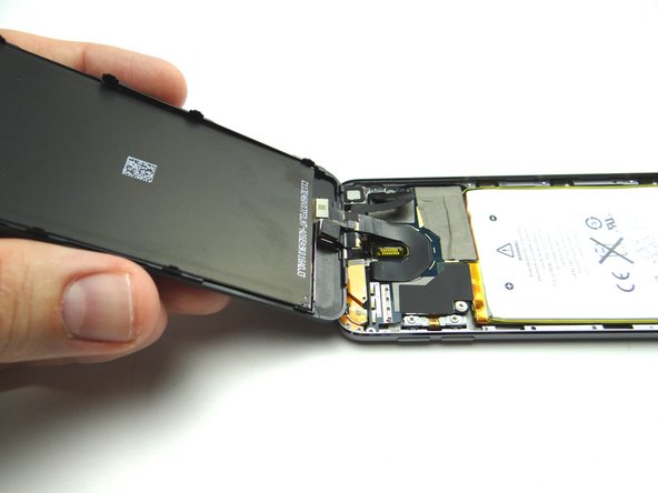
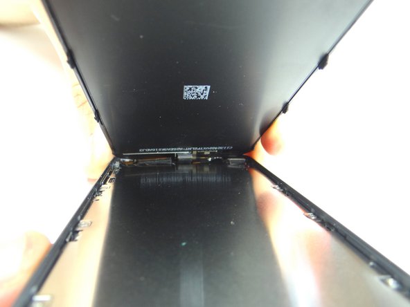
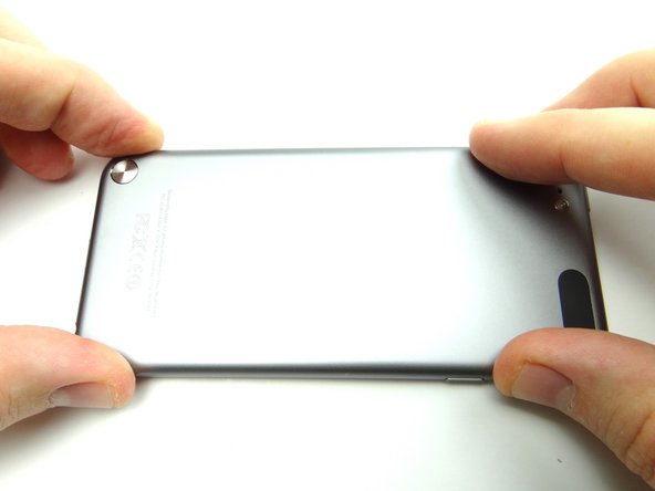
Picture 1: There is adhesive across the bottom on either side of the home button.
-
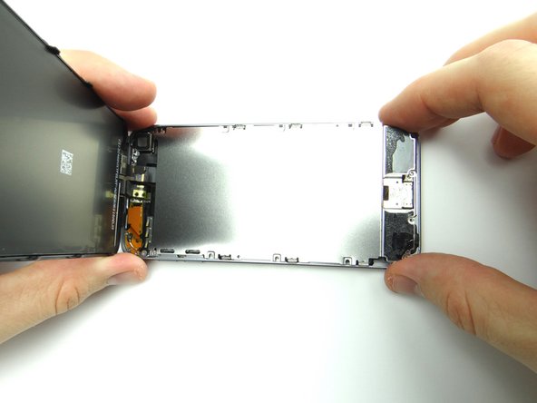
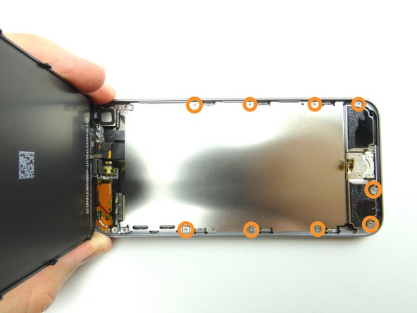
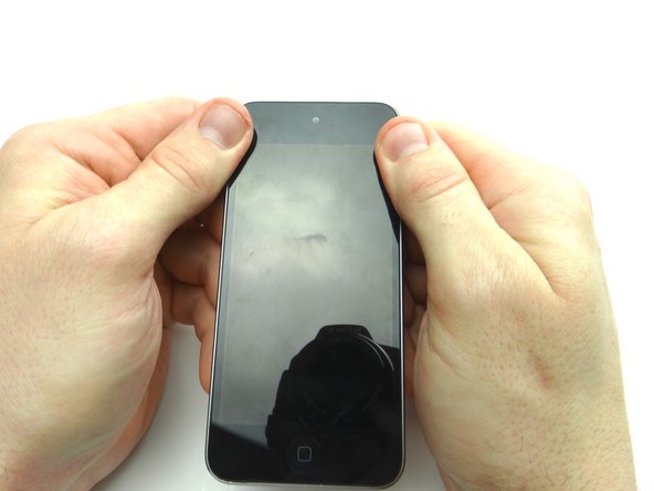
Picture 2: There are 3 clips on each side of the screen.
-
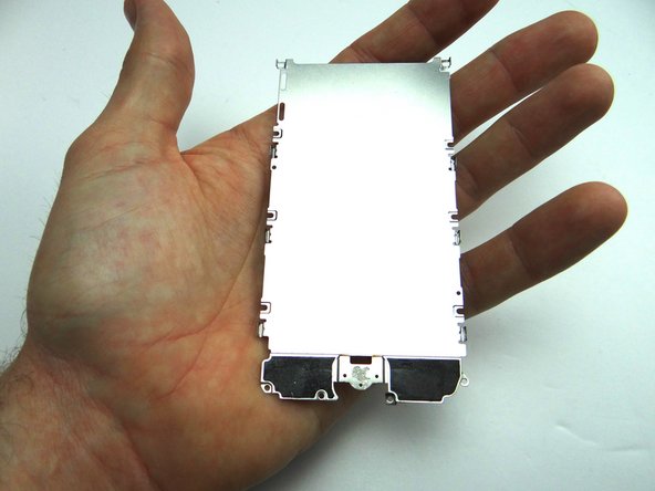
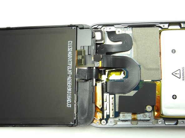
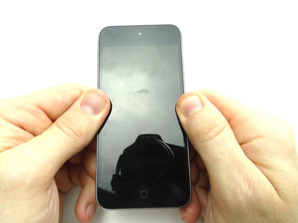
Picture 3: There are 2 clips at the top of the screen.
-
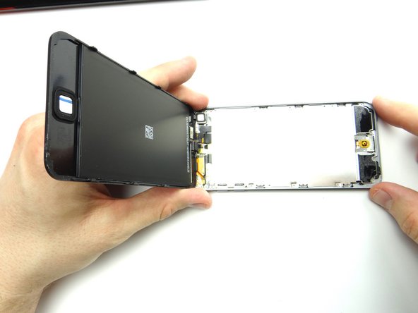
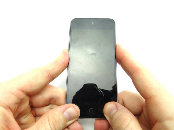
You'll be releasing the clips and adhesive in the next steps to open the iPod:
-
-
-
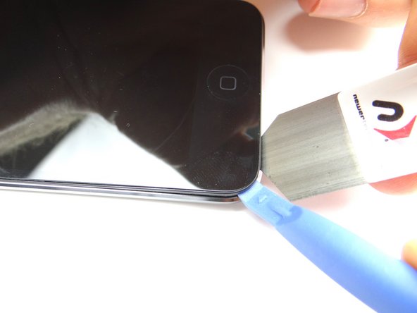
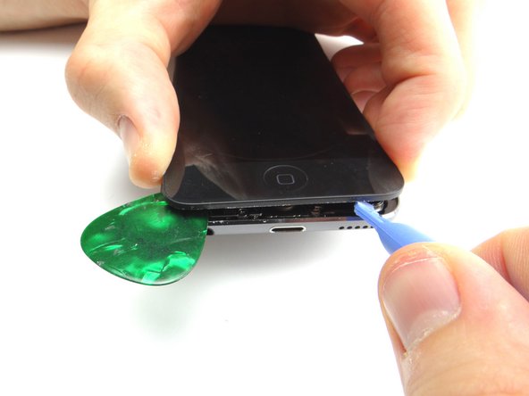
Picture 1: Place the suction cup on the screen just above the home button. Apply low-level heat (100 degrees Celsius) to the bottom edge of the iPod for about a minute.
-
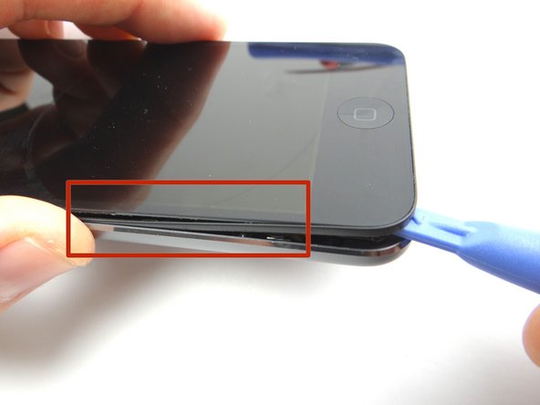
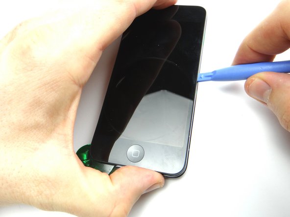
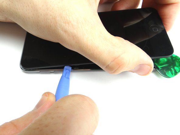
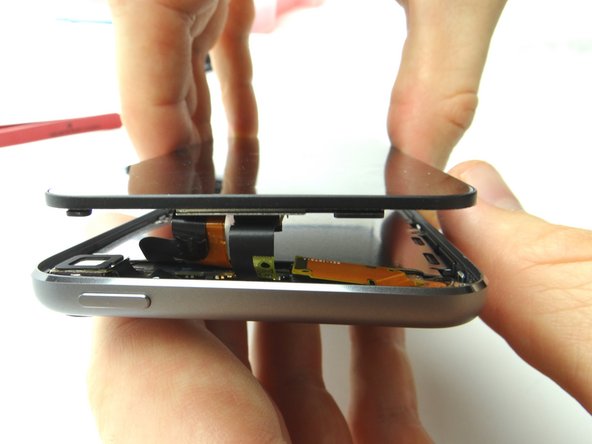
Pictures 2 & 3: Use the suction cup to pull the front panel up just enough to wedge the blue pry tool in between the front panel and rear case.
-
Remove suction cup once you've wedged the blue pry tool.
-
If you're unable to create suction (e.g. the screen is badly cracked), we provide a back-up method in the next step.
-
-
-
Skip this step if the suction cup method worked.
-
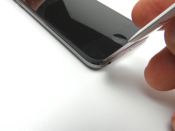
Picture 1: Wedge iSesamo underneath the black bezel around the screen.
-
Picture 2: Pry up just enough to wedge blue pry tool and remove the iSesamo.
-
Picture 3: Continue prying up under the bezel with the blue pry tool.
-
If you're replacing the screen and it comes with the bezel pre-installed, pry between the screen and bezel to minimize the likelihood of damaging the rear case.
-
-
-
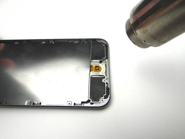
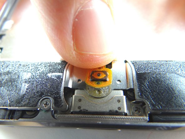
Picture 1: Apply low-level heat (100° Celsius) to the home button contact for 30 seconds.
-
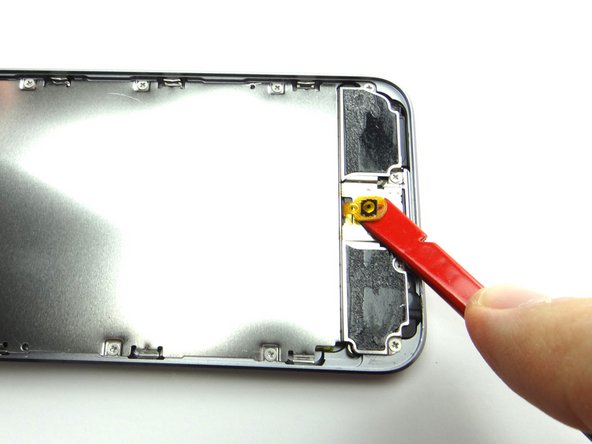
Picture 2: Use the spudger to peel up the home button contact.
-
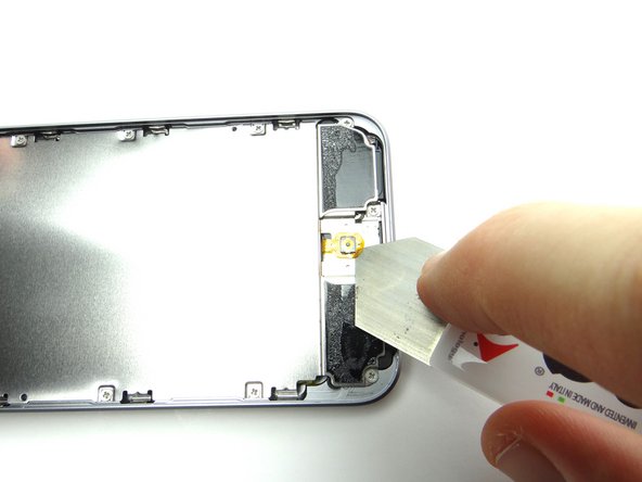
Picture 3: If you can't wedge the spudger under the home button contact, use your fingernail or iSesamo to get it started.
-
Don't try to remove the home button contact - it's still connected to the logic board.
-
-
-
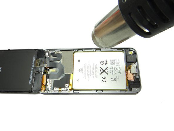
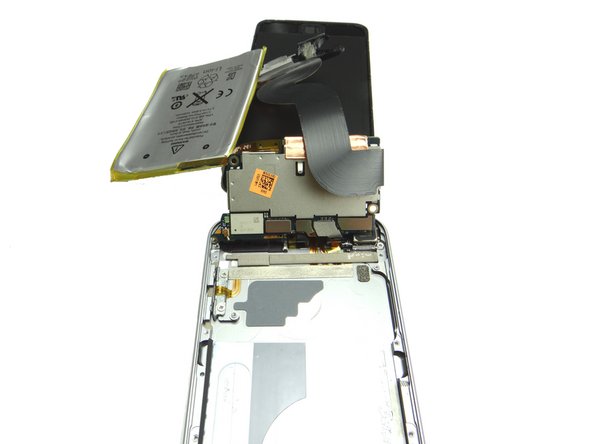
Picture 1: Apply low-level heat in 30 second increments as needed to loosen the battery adhesive.
-
Hold the heat gun three inches from the battery to avoid overheating.
-
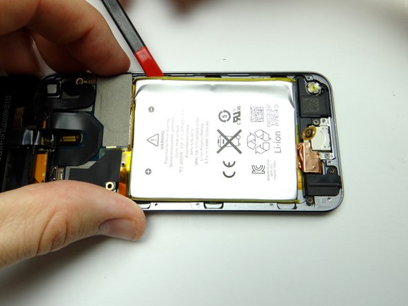
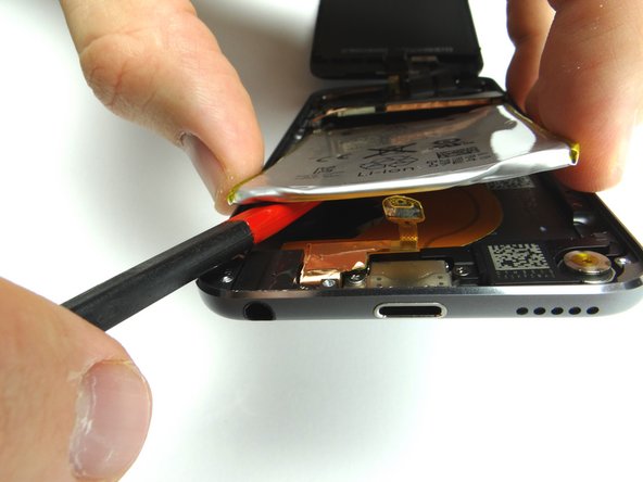
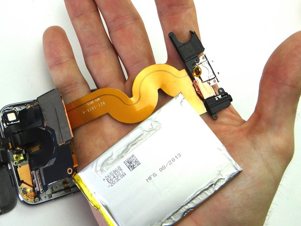
Picture 2: Use the spudger to pry up the upper right corner of the battery.
-
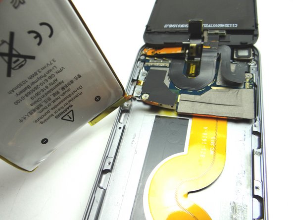
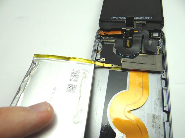
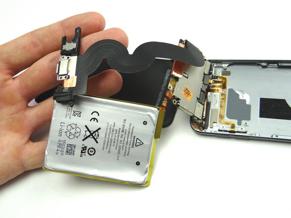
Picture 3: Work your way around the battery to free it, taking care not to tear the charging port cable underneath.
-
-
-
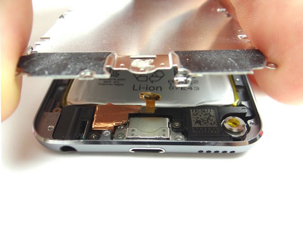
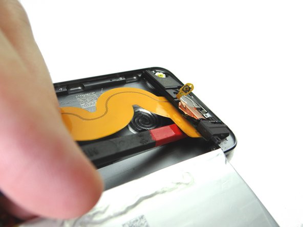
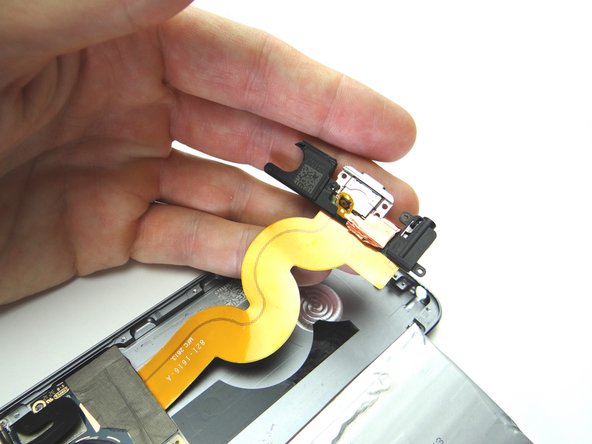
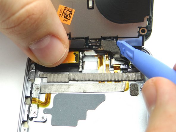
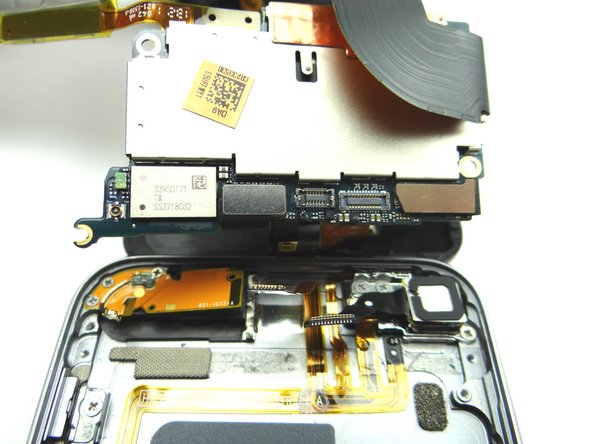
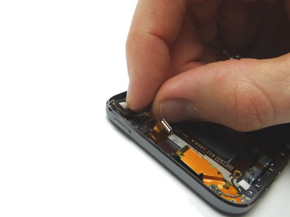
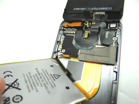
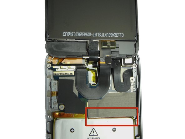
Picture 1: Push the flat end of the spudger under the charging port ribbon cable and pry up until you're able to grab the assembly with your fingers.
-
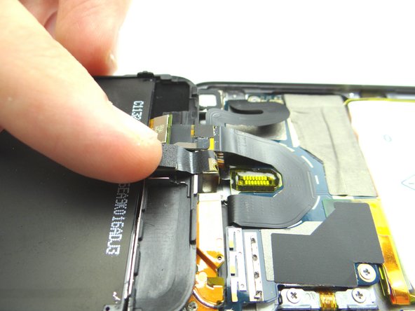
Picture 2: Use your fingers to carefully finish removing the assembly, noting the ribbon cable, headset jack, charging port and loudspeaker are all connected.
-
-
-
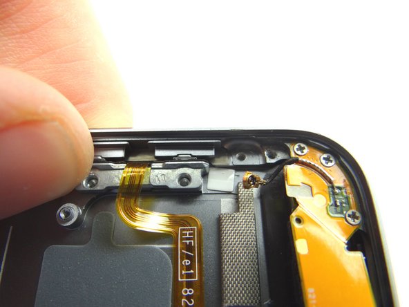
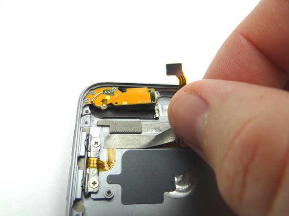
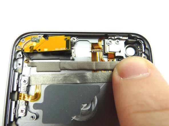
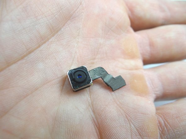
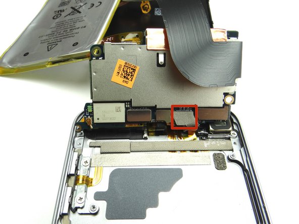
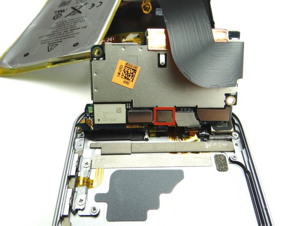
Pictures 1 & 2: Peel up the camera cable then use the blue pry tool to remove the camera from its socket. Place in COMPARTMENT B.
-
-
-
Starting on the left, peel up the tape roll covering the buttons cable. Place in COMPARTMENT C.
-
Then starting on the right, peel up the strip of tape just below. Place in COMPARTMENT C.
-
-
-
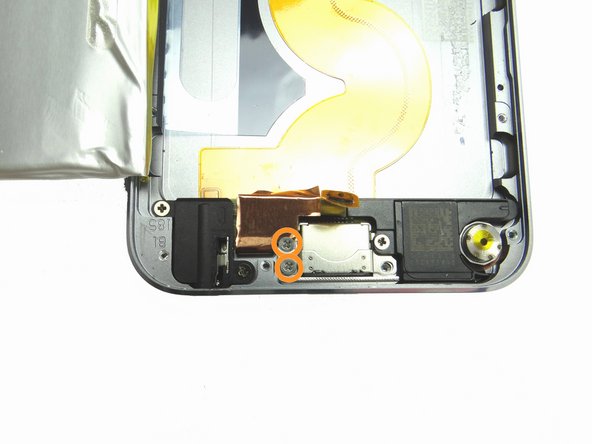
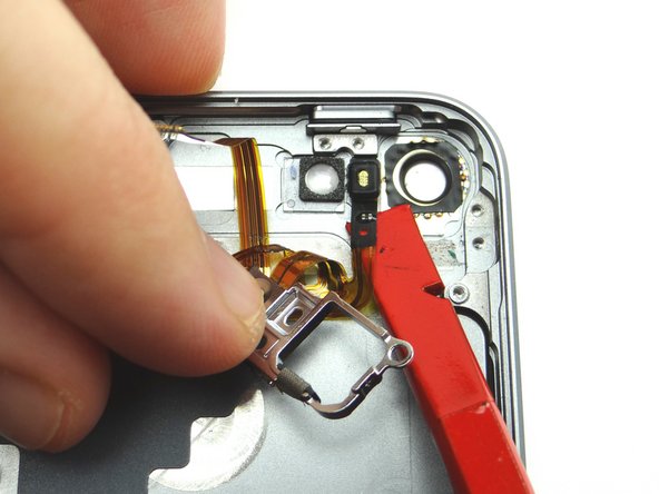
Remove two 2.0 mm #00 Phillips screws securing the volume button end of the button ribbon cable to the rear case. Place screws in SLOT 7.
-
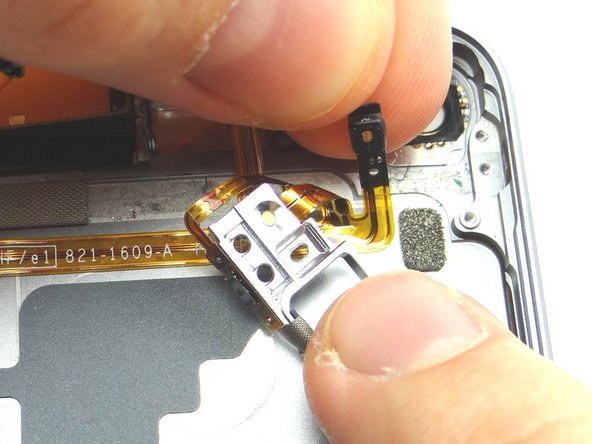
Use tweezers to lift volume button bracket out of the way just enough to allow the volume buttons to be extracted.
-
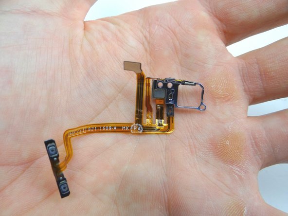
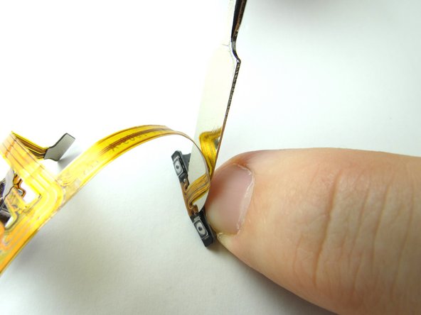
Use tweezers to remove volume buttons. Place in COMPARTMENT D.
-
-
-
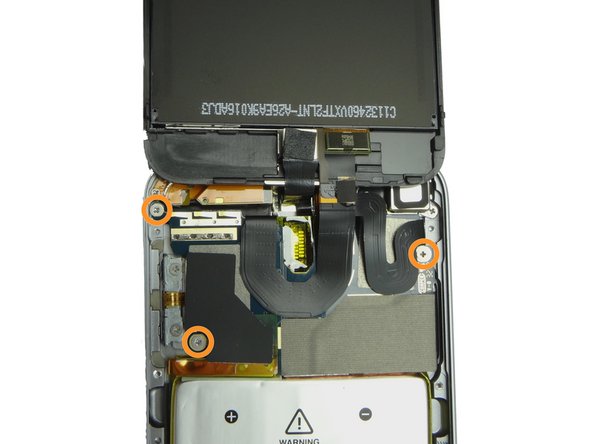
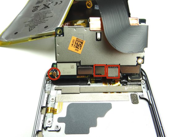
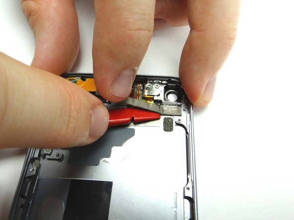
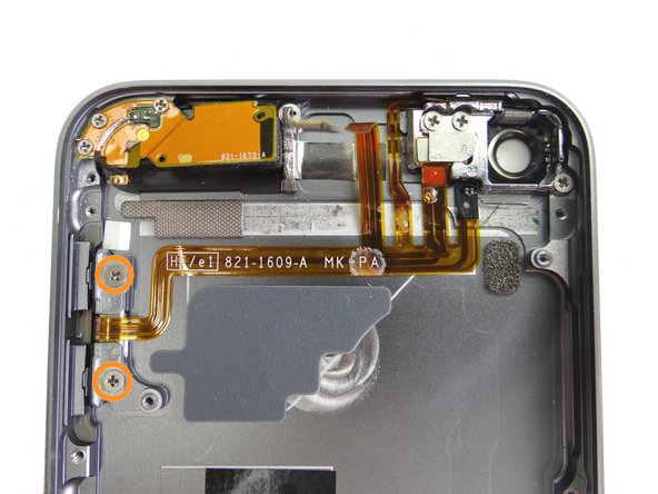
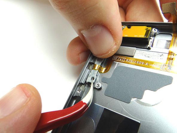
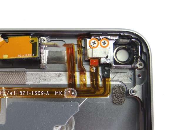
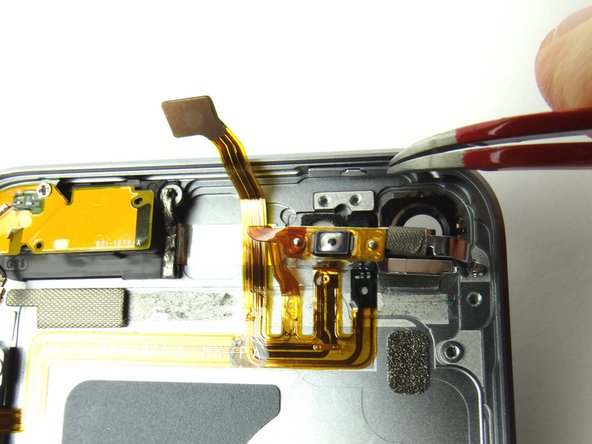
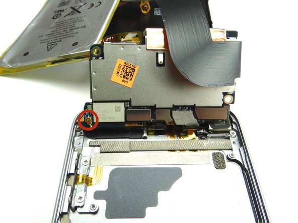
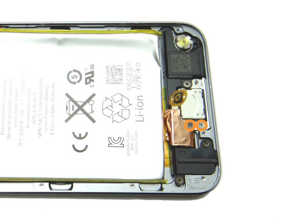
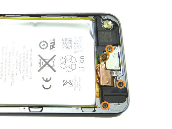
Picture 1: Remove two 2.3 mm #00 Phillips screws. Place screws in SLOT 8.
-
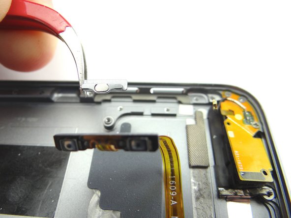
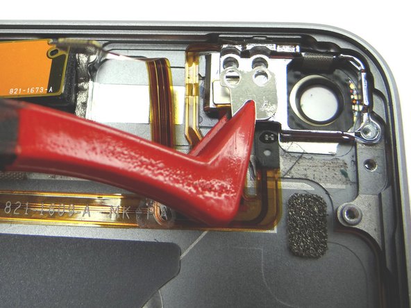
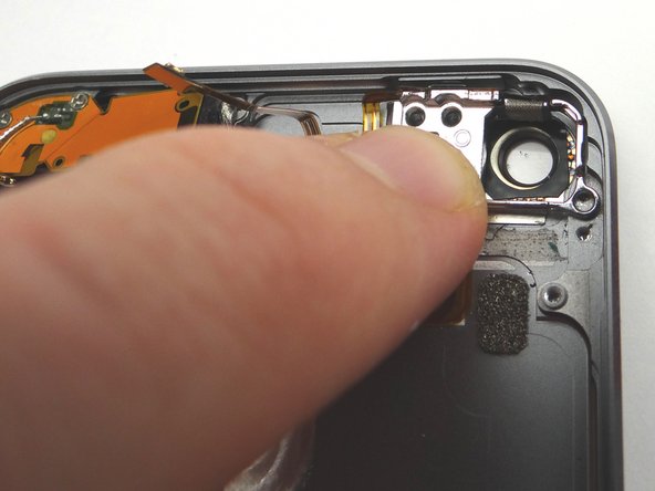
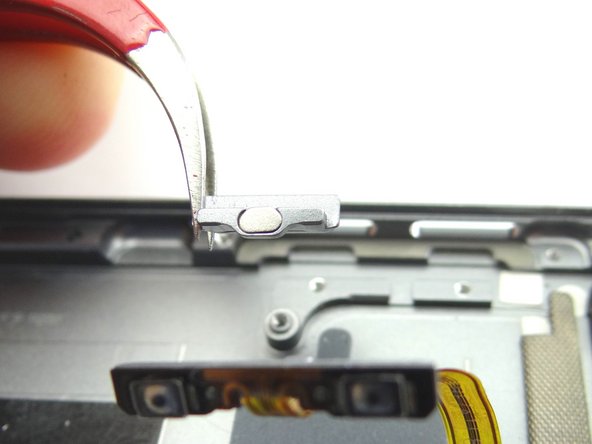
Picture 2: Use plastic tweezers to remove small plate. Place in COMPARTMENT E.
-
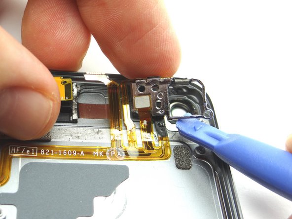
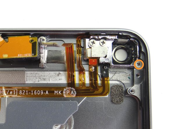
Picture 3: Remove one 1.6 mm #00 Phillips screw. Place screw in SLOT 9.
-
-
-
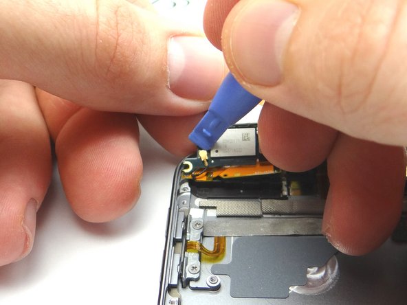
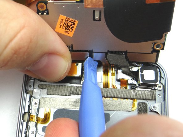
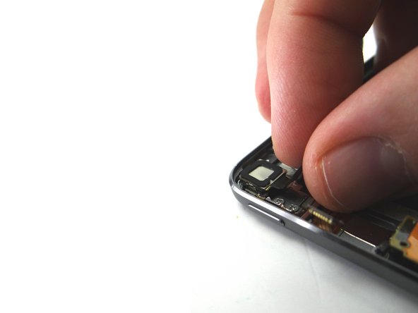
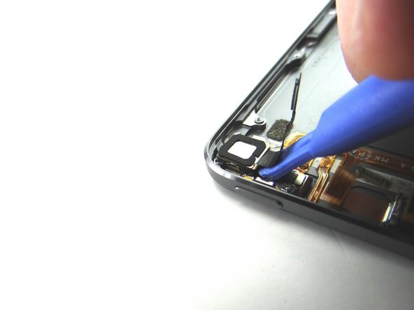
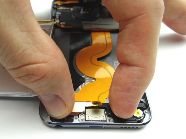
Insert the spudger at the bottom of the microphone and push it up to free it from the rear case.
-
Grab the microphone with your fingers and continue peeling up
-
-
-
From COMPARTMENT D, attach volume buttons bracket to volume buttons cable.
-
-
-
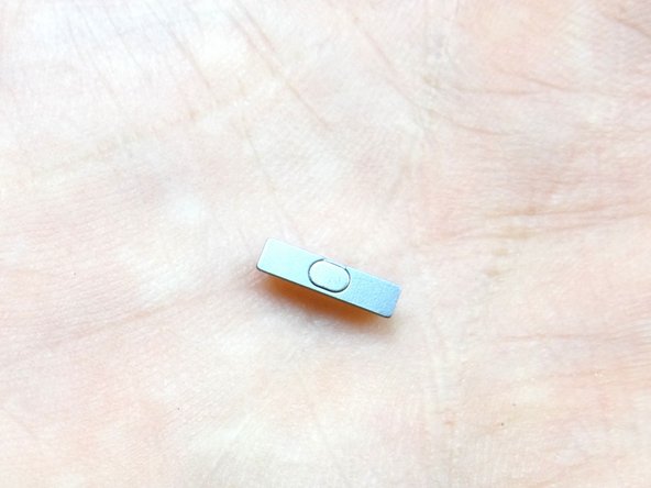
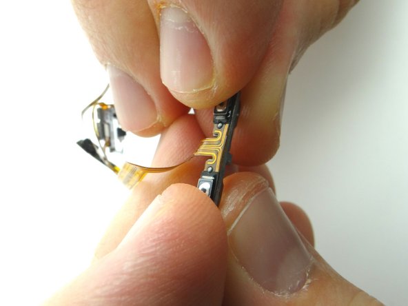
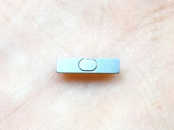
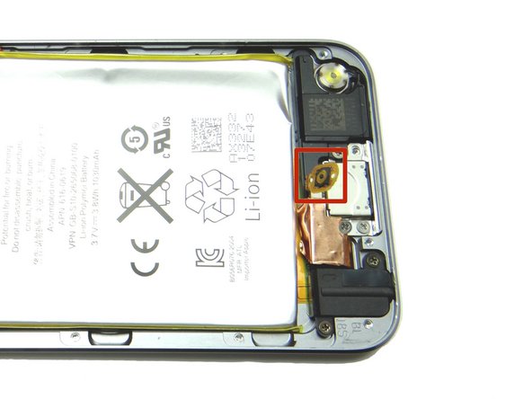
Picture 1: Retrieve the power button from COMPARTMENT E. Maintain the orientation when seating the power button.
-
Use tweezers to seat the power button.
-
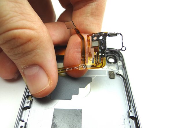
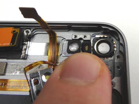
Seat rear camera frame.
-
-
-
Picture 1: From COMPARTMENT D, replace volume buttons. Note the orientation when seating.
-
Seat volume buttons bracket.
-
Replace two 2.0 mm #00 Phillips screws securing the volume button end of the button ribbon cable to the rear case from SLOT 7.
-
-
-
From COMPARTMENT B, seat the camera in its socket on the rear case.
-
-
-
Attach rear case to the front panel, logic board, battery and charging port assembly over the next few steps.
-
-
-
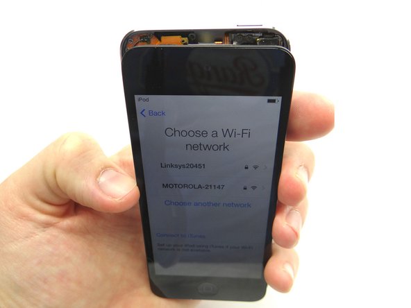
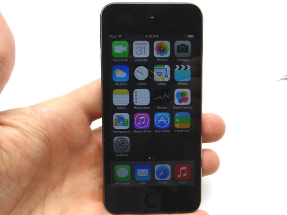
Picture 1: Power up the device and test the LCD and digitizer before closing it.
-
After reassembling an iPod, it is common to see a screen with lines down the LCD or a white screen. Try turning it off and back on. If that doesn't work, you may have to perform a soft reset. (press and hold power and home buttons simultaneously for ten seconds).
-
Picture 2: Place the clips at the top of the front panel before seating the rest of front panel.
-
Picture 3: Finish seating the remaining clips in the next step.
-