-
-
Before disassembly, thoroughly wash and dry your hands. Power down the device.
-
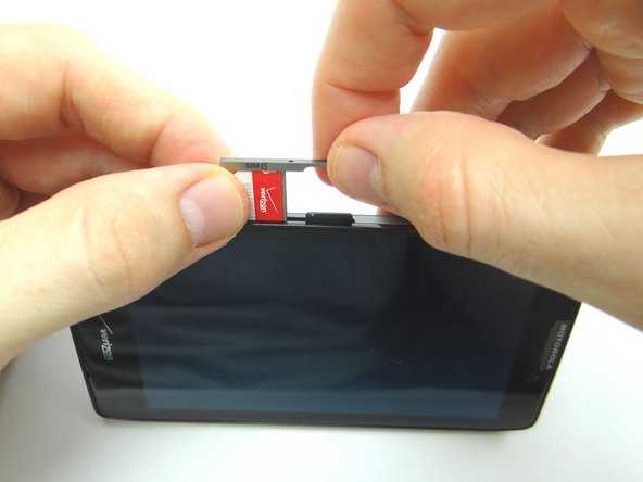
Find the opening in the SIM card tray roughly an inch above the charging port. Gently push a small paper clip into the opening to 'pop up' the SIM card tray.
-
Remove the tray, SIM card and SD card. Place all three in COMPARTMENT A.
-
-
-
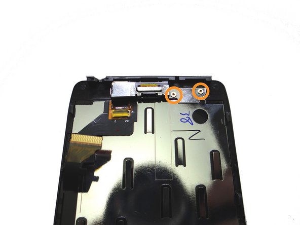
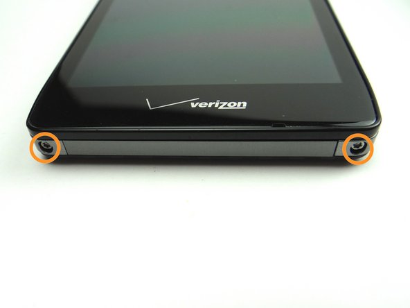
Picture 1: Remove two 4.8 mm T5 Torx screws. Place in SLOT 1.
-
Picture 2: With your thumbs placed on the screen as pictured, shimmy the screen up from the bottom of the phone.
-
Picture 3: The screen comes up just a couple millimeters as shown.
-
-
-
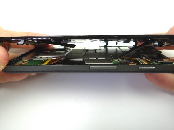
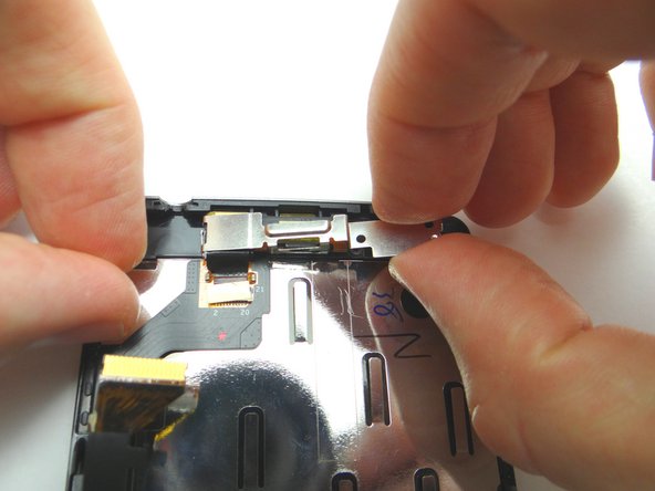
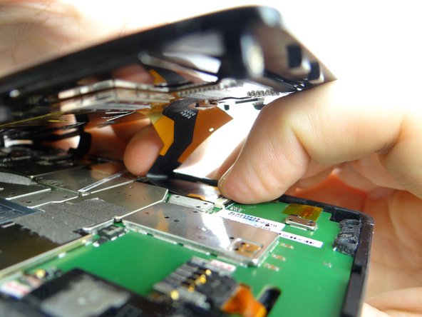
Lift the front panel an inch above the rear panel.
-
The component cable connector is next to the power button: peel up the yellow Kapton tape covering the connector.
-
-
-
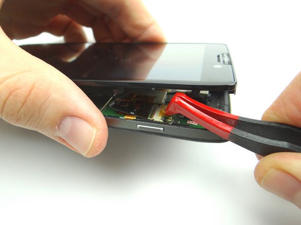
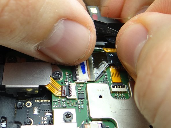
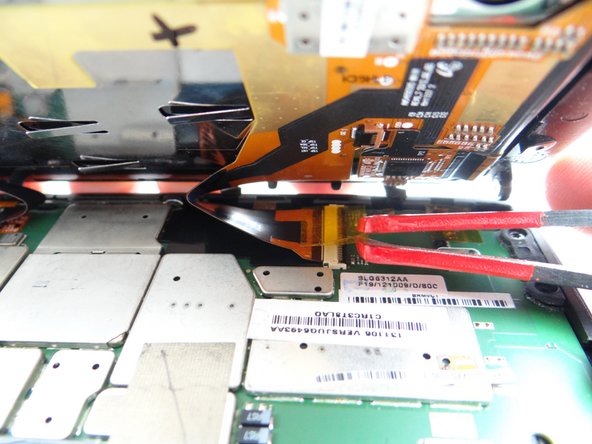
Picture 1: Use flat end of spudger to push the black ZIF connector bar into open position as shown.
-
Picture 2: Gently guide the component cable out of the ZIF connector.
-
-
-
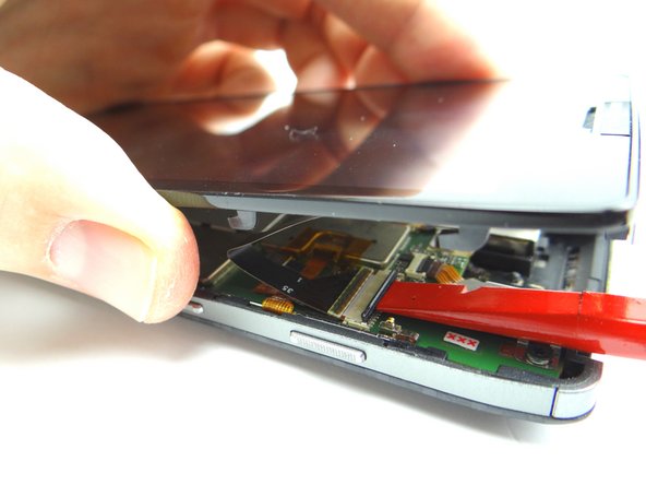
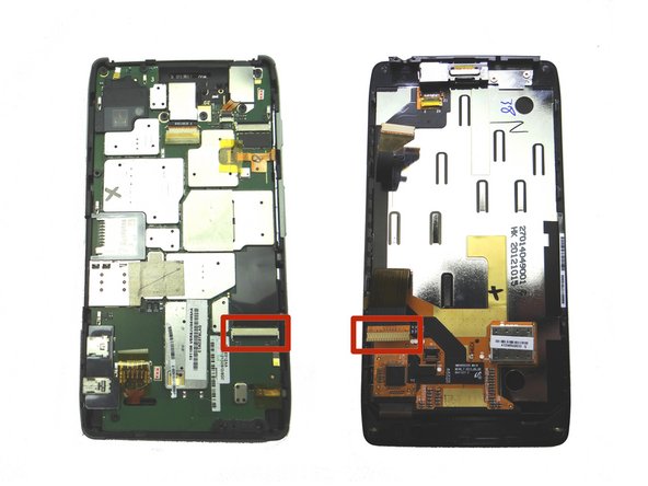
The display cable connector is two inches down from the component connector:
-
Picture 1: Peel up yellow Kapton tape with plastic tweezers. Adhere the tape to the wall of COMPARTMENT E. (You'll need a piece of Kapton tape for reassembly to help hold the display cable in place.)
-
Picture 2: Use flat end of spudger to push the black ZIF connector open.
-
Picture 3: Gently guide the display cable out of the ZIF connector.
-
-
-
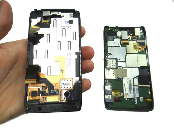
Separate the front and rear panels and place them in ZONES I & II.
-
-
-
Remove two 2.1 mm T3 Torx screws from bracket. Place in SLOT 2.
-
Remove bracket. Place in COMPARTMENT B.
-
-
-
Strong adhesive holds the earpiece speaker and component cable assembly in place:
-
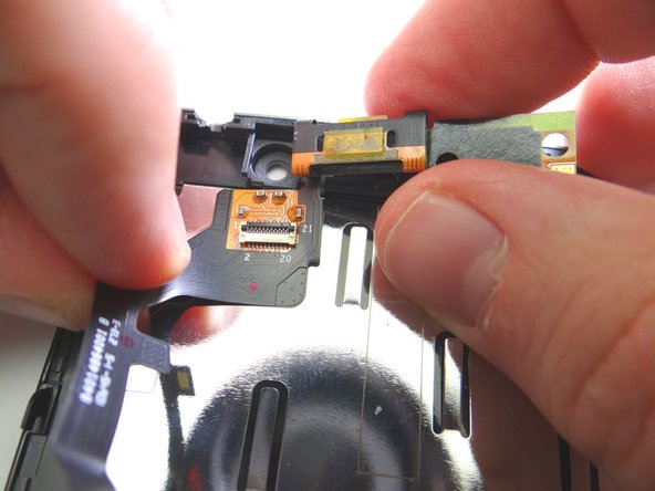
Picture 1: Push the flat end of spudger under earpiece speaker to free it from the adhesive.
-
Picture 2: Continue peeling up the speaker and cable assembly up with both hands until free.
-
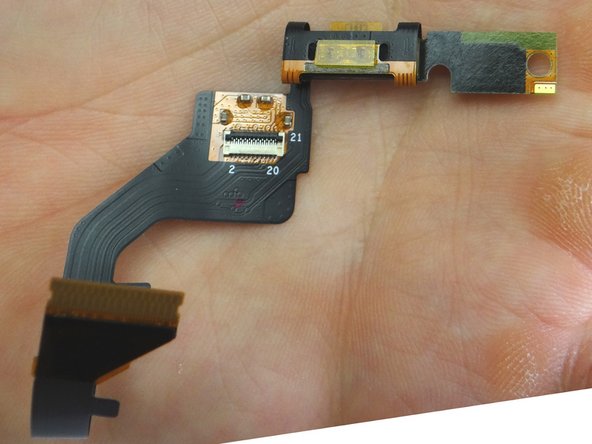
Picture 3: Place in COMPARTMENT C.
-
-
-
Picture 1: From COMPARTMENT C, replace earpiece speaker and component cable assembly.
-
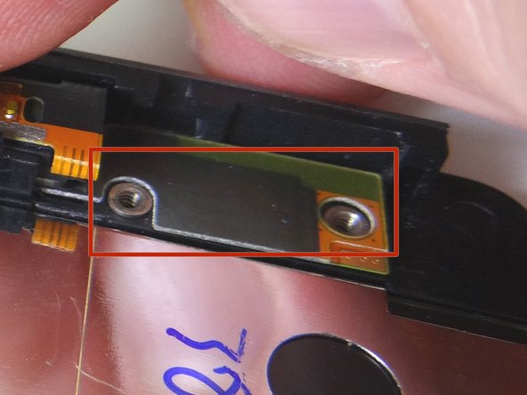
Picture 2: Make sure the openings for the screw slots on the cable line up with the slots on the front panel.
-
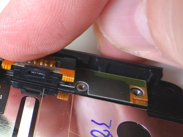
Picture 3.: Push earpiece speaker into place.
-
-
-
Replace bracket from COMPARTMENT B.
-
Repalce two 2.1 mm T3 Torx screws from bracket from SLOT 2.
-
-
-
Connect component cable:
-
Guide component cable into open ZIF connector. Hold component cable in place with one hand, while closing ZIF connector with your thumb on opposite hand.
-
-
-
Picture 1: Connect display cable:
-
Picture 2: Guide display cable into open ZIF connector. Hold display cable in place with one hand, while closing ZIF connector with your thumb on opposite hand.
-
Picture 3: Cover the display cable connector with Kapton tape from COMPARTMENT E.
-
The display cable has a tendency to come loose when closing the front panel on the rear panel. It's important to replace the yellow Kapton tape to ensure the cable is held in place.
-
-
-
Seat the front panel on the rear panel up a couple millimeters from the bottom of the rear panel. Slide the front panel down into place.
-
Picture 2: Replace two 4.8 mm T5 Torx screws from SLOT 1.
-
-
-
From COMPARTMENT A, replace tray, SIM card and SD card.
-
Power up the device and test the replacement component or components.
-