-
-
Power down the device.
-
Remove the battery cover and place it in ZONE I.
-
-
-
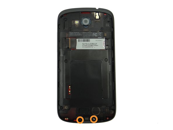
Remove two 3.6 mm T4 Torx screws. Place them in SLOT 1.
-
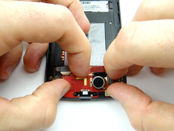
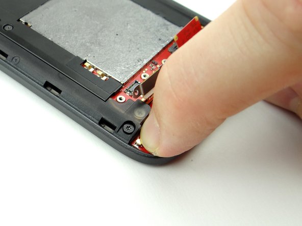
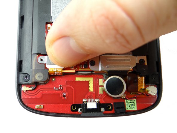
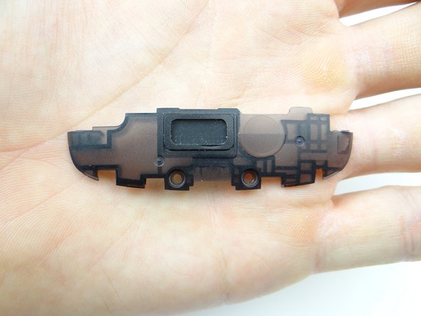
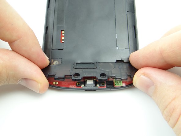
Use the pointed end of the spudger to pry up the speaker assembly. Remove it with your fingers and place it in ZONE I (below battery cover).
-
-
-
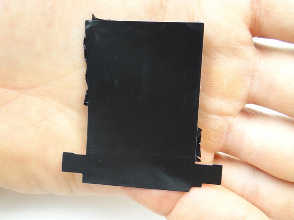
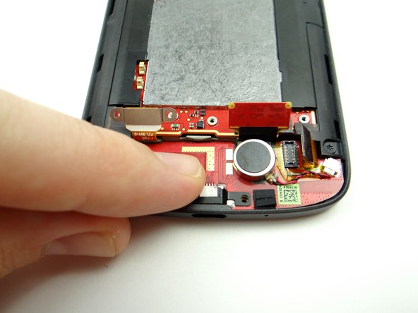
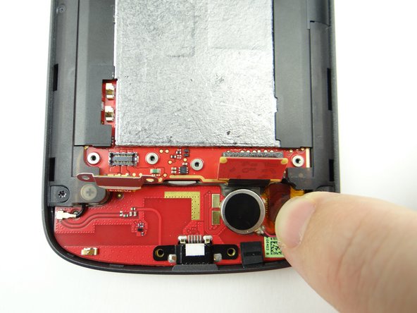
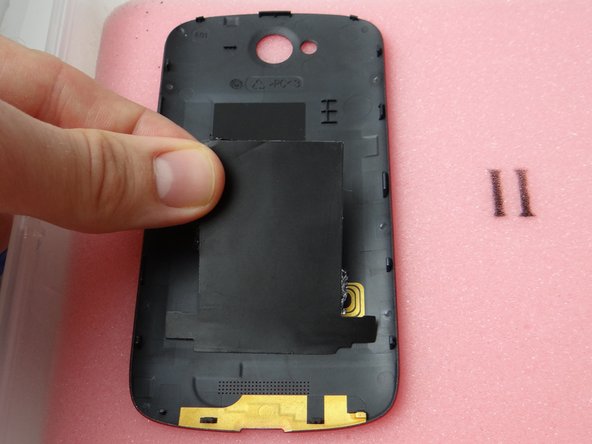
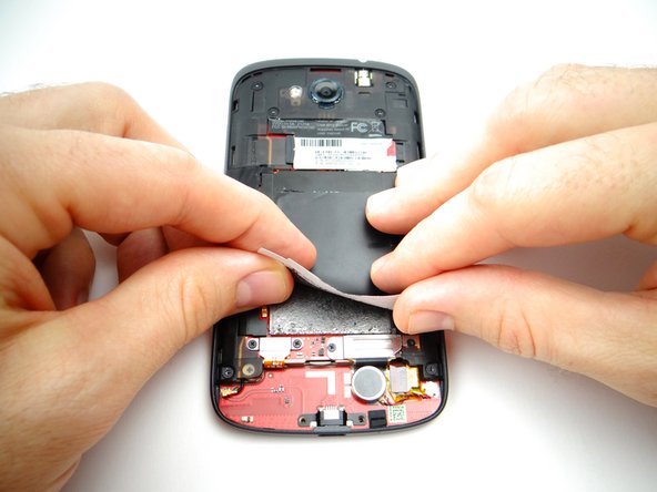
Peel up the tape covering the logic board.
-
Place it on the inside of the battery cover in ZONE I, sticky side down.
-
-
-
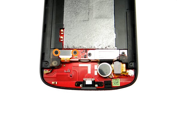
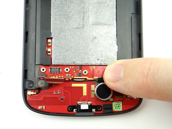
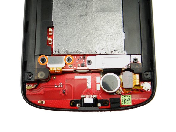
Picture 1: Remove two 1.8 mm #00 Phillips screws. Place in SLOT 3.
-
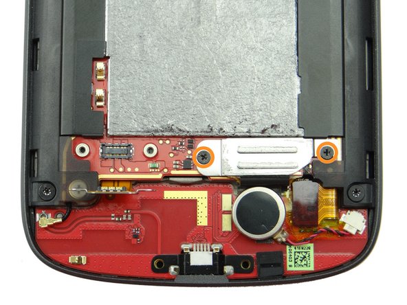
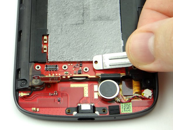
Picture 2: Remove the shield held down by the screws and place it in SLOT 3 (with the screws).
-
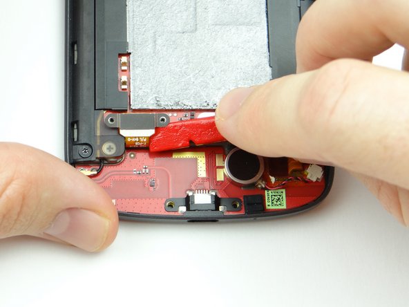
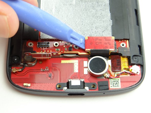
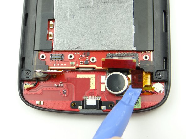
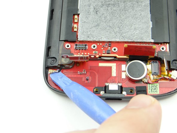
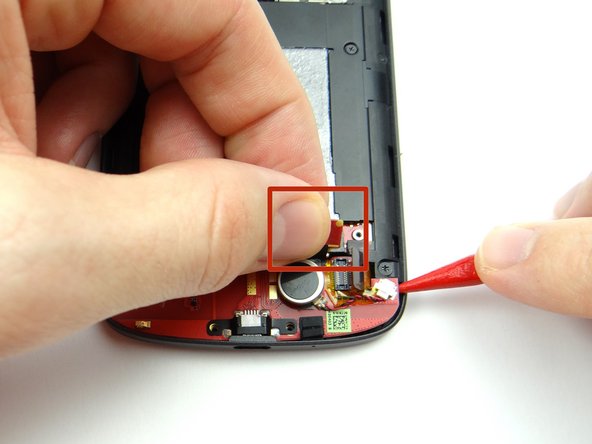
Use blue pry tool to disconnect charging port daughter board cable.
-
-
-
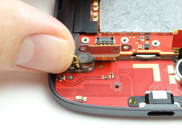
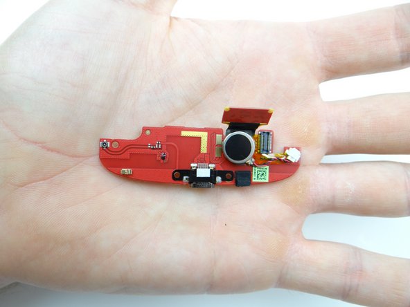
Retrieve charging port board from ZONE II.
-
-
-
Seat battery connector.
-
Replace two 1.7 mm #00 Phillips screws from SLOT 2 to secure battery connector.
-
-
-
Replace speaker assembly from ZONE I:
-
Position top edge first then push speaker assembly fully into place.
-
Replace two 3.6 mm T4 Torx screws from SLOT 1 to secure speaker assembly.
-
-
-
Seat battery cover from ZONE I.
-
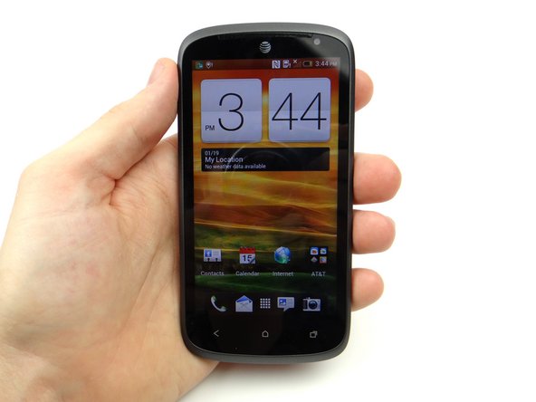
Power up and test device.
-