-
-
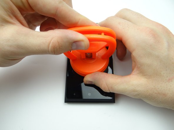
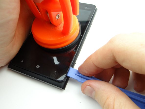
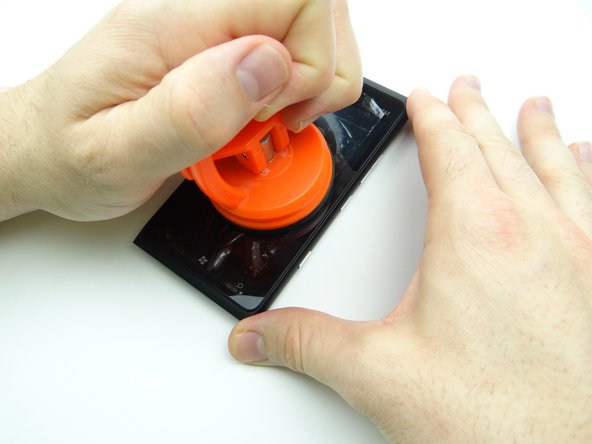
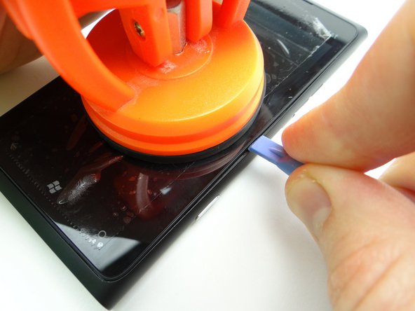
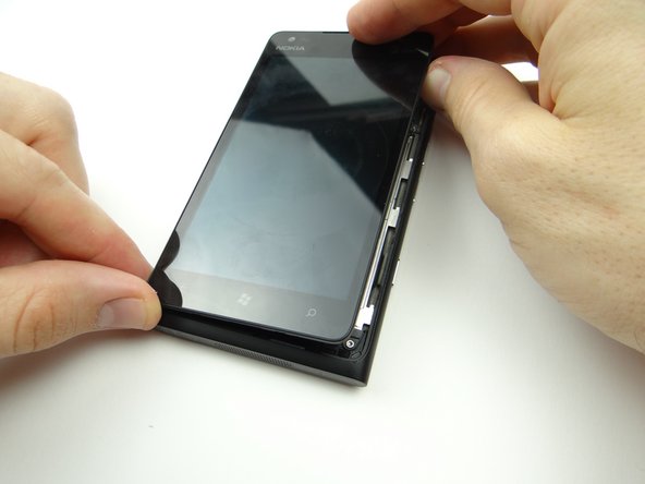
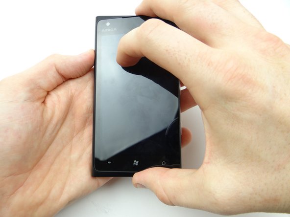
Picture 1: Place a large suction cup in the center of the screen.
-
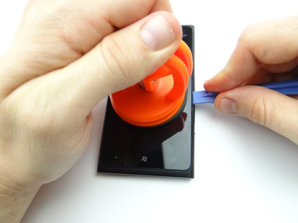
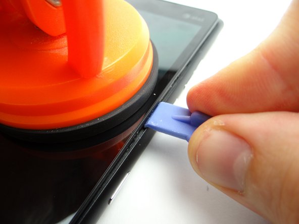
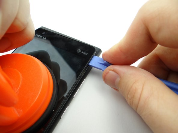
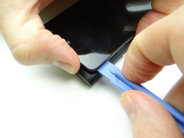
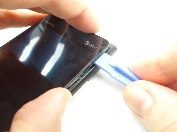
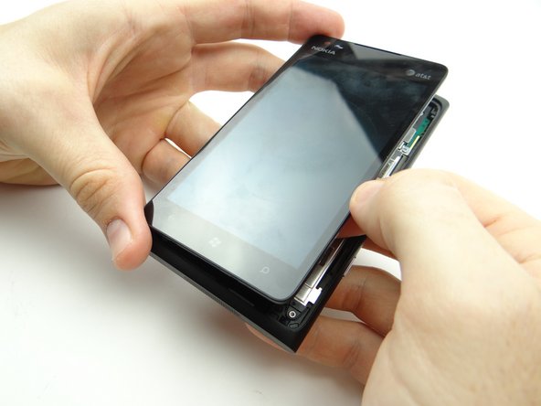
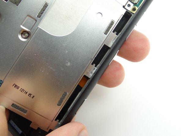
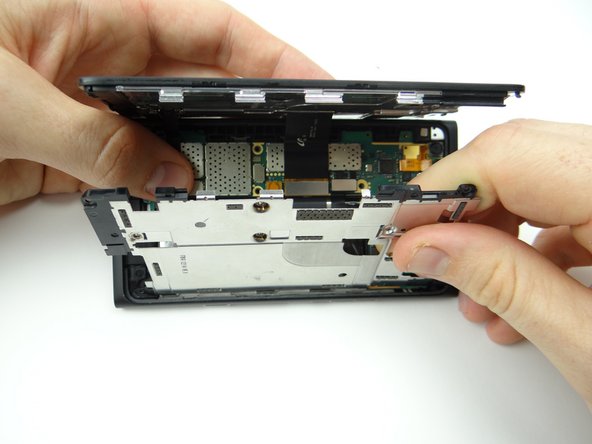
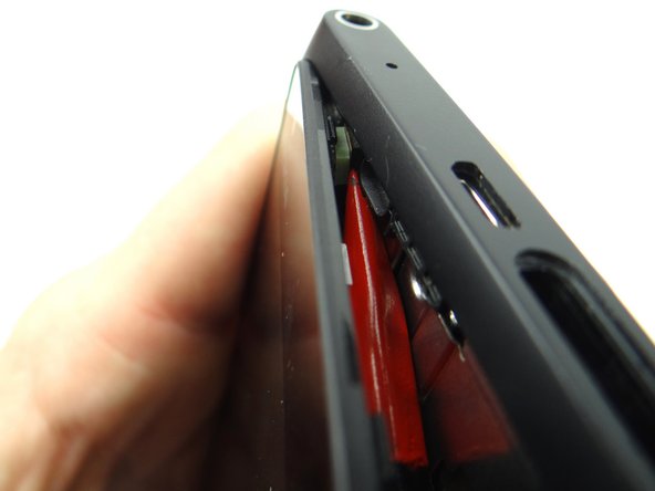
Pictures 2 & 3: Pull up the screen slightly while wedging the blue pry tool in the center of the right side, between the display assembly bezel and rear case.
-
-
-
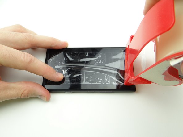
Put packing tape over the screen to hold the broken pieces of glass together. Smooth out the bubbles.
-
Go back two steps to open the device OR use the iSesamo (shown in the next step) if the screen still won't budge.
-
-
-
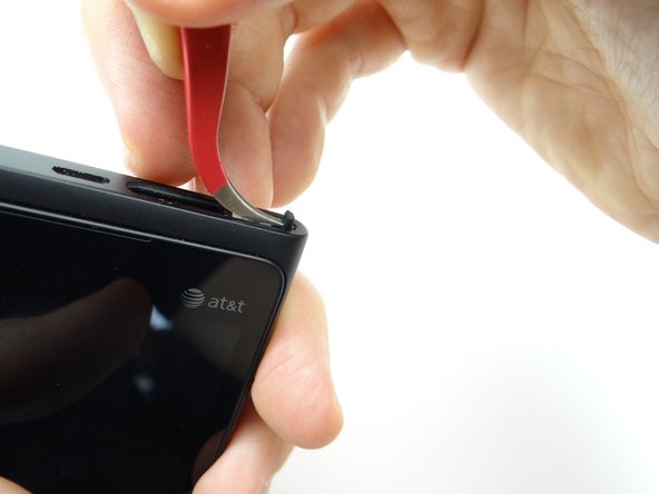
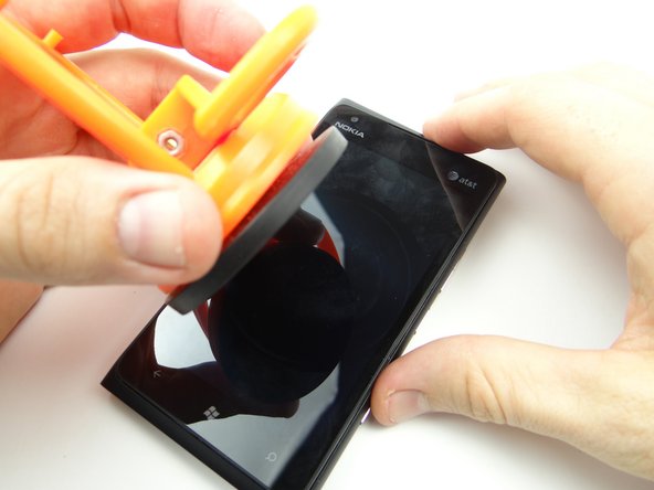
If you can't create suction, use the iSesamo to pry open the screen:
-
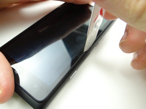
Pictures 1: Insert the tip of the iSesamo between the display assembly and rear panel.
-
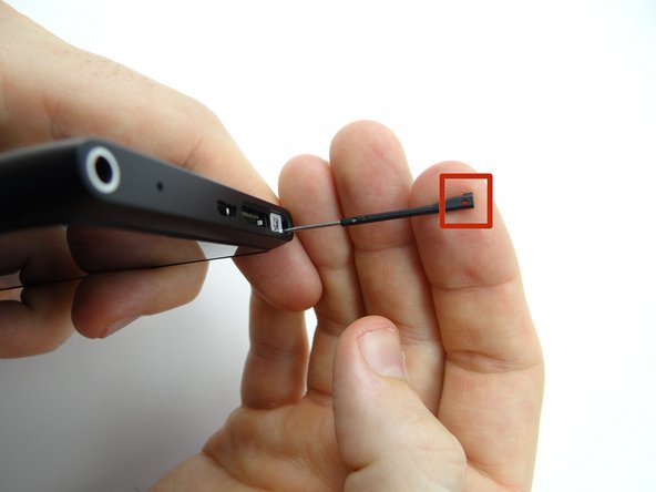
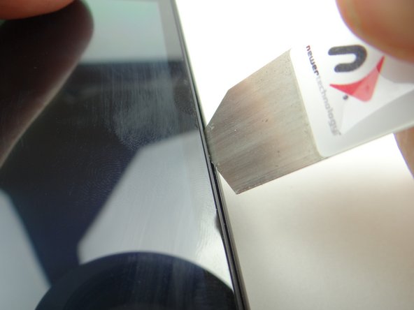
Only insert the iSesamo a couple millimeters as shown in Picture 2.
-
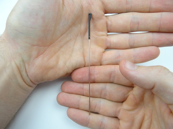
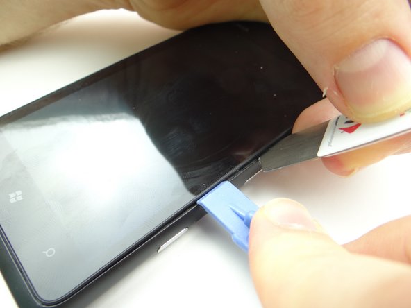
Pictures 2 & 3: Use the iSesamo to pry open the device just enough to insert a wide blue pry tool face down.
-
-
-
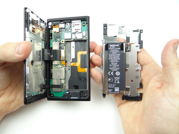
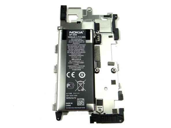
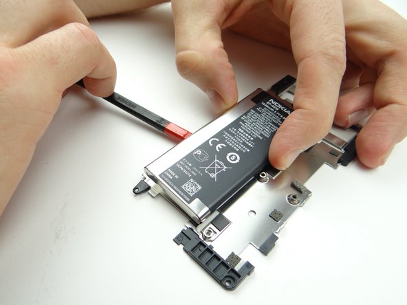
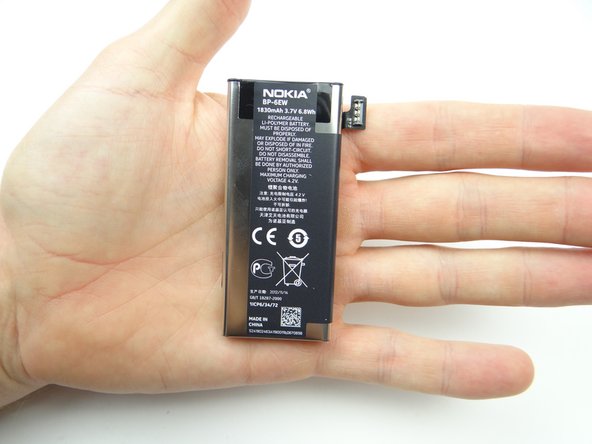
The battery is adhered to the underside of the mid-plate and should come up with it (as shown in the next step).
-
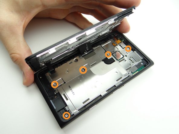
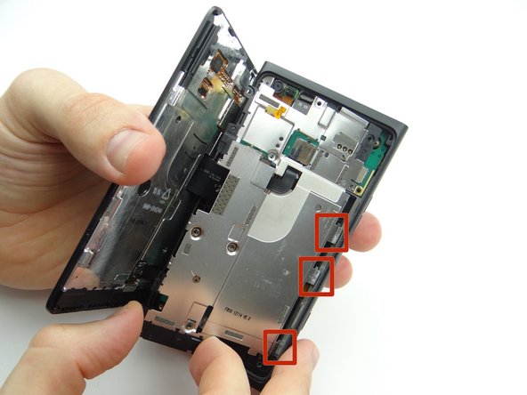
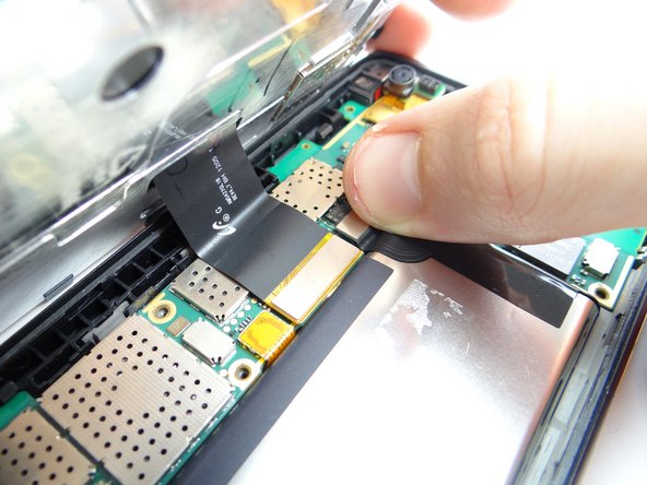
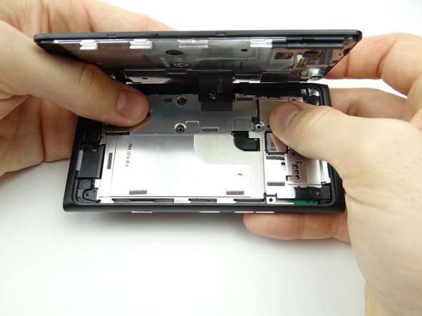
Picture 1: Wedge the flat end of the spudger under the mid-plate exactly where shown.
-
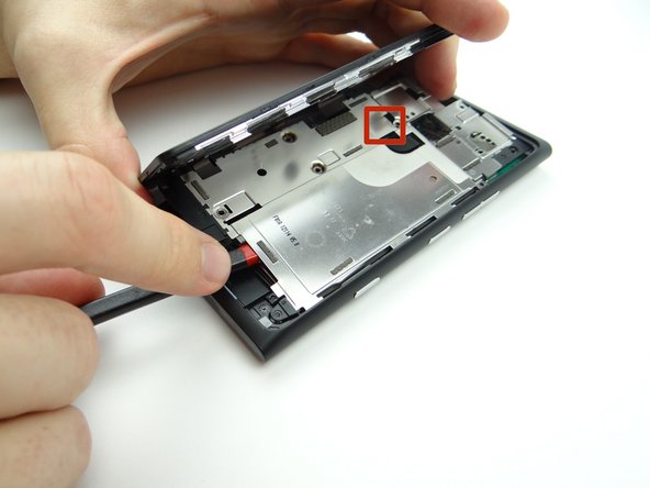
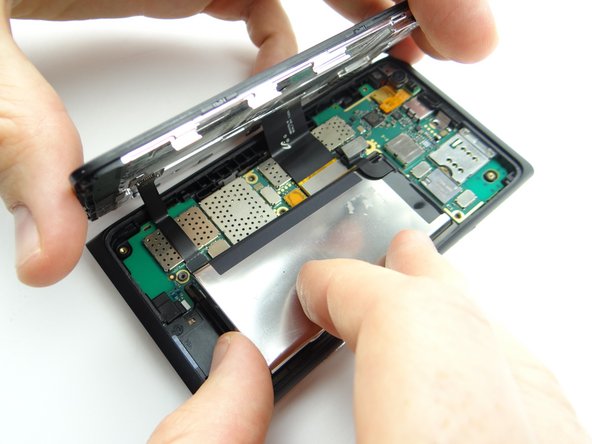
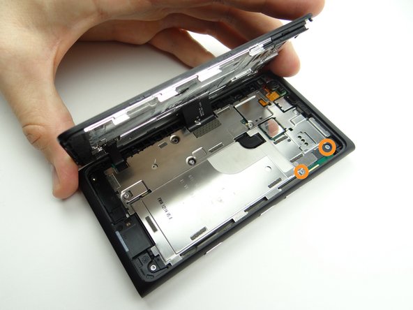
Picture 2: Lift from the top and bottom taking care not to torque the battery connector (red square in Picture 2).
-
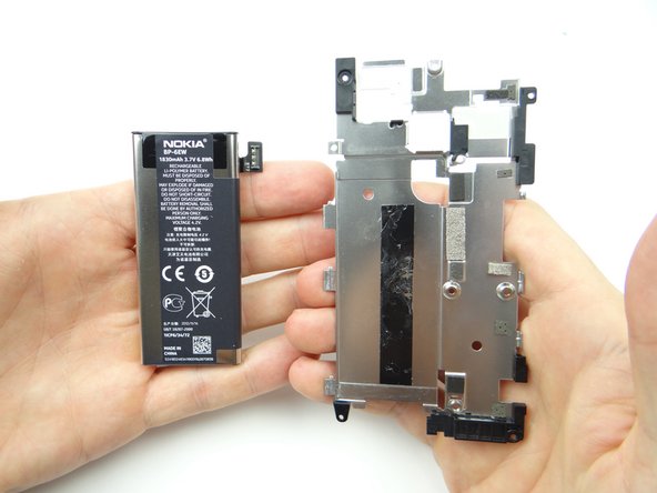
Picture 3: Guide the clips on the mid-plate free from the rear case.
-
-
-
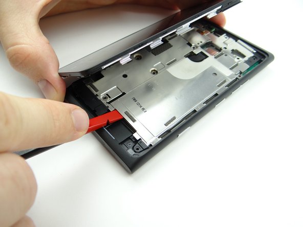
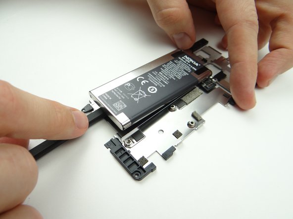
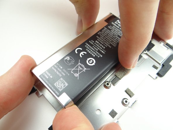
Wedge the flat end of the spudger at the center-bottom of the battery. Push halfway up.
-
Turn the spudger to cut through the adhesive holding the battery.
-
-
-
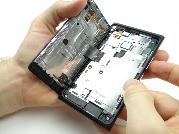
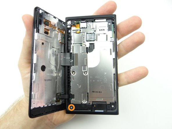
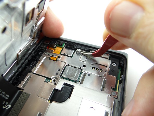
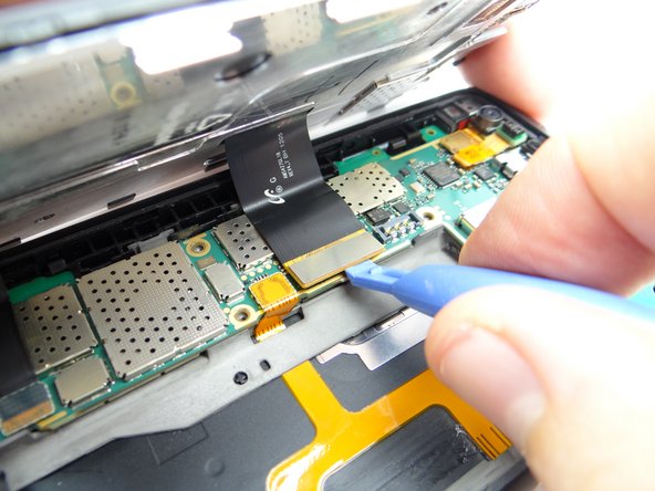
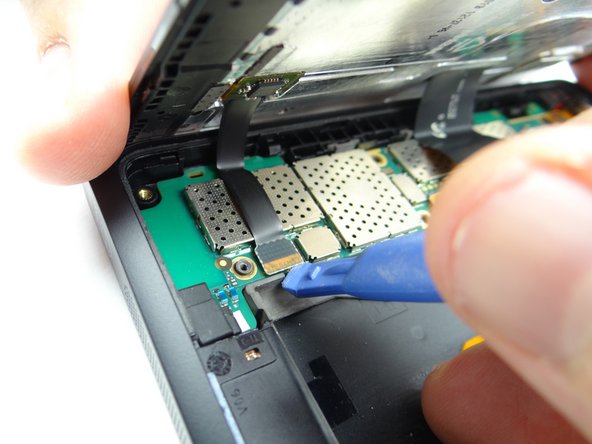
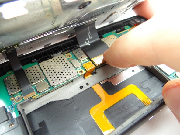
Close the device to a roughly 70° angle so there's no tension on the LCD cable as you use a blue pry tool to disconnect it.
-
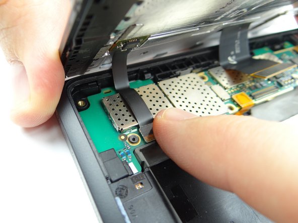
Disconnect digitizer/soft keys cable.
-
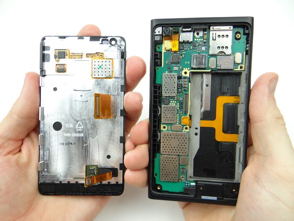
Place display assembly and rear panel on the anti-static foam.
-
-
-
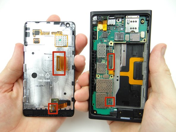
Place the display assembly over the rear panel at a roughly 70° angle so there's no tension on the display cables as you seat them on the logic board.
-
Seat digitizer & soft keys cable.
-
Seat LCD cable.
-
-
-
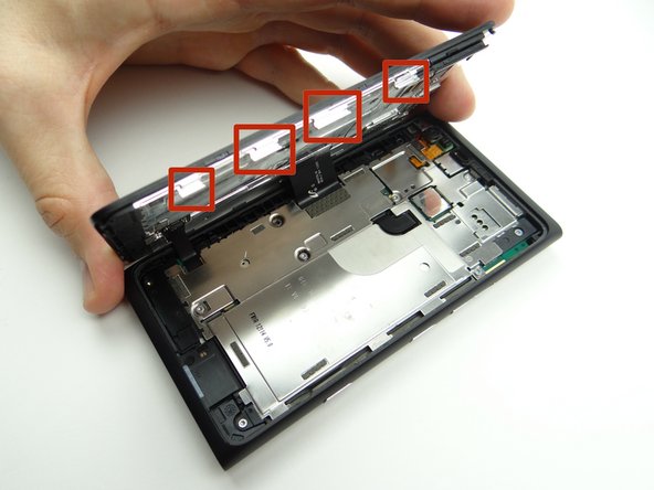
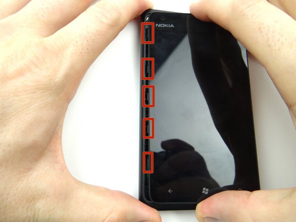
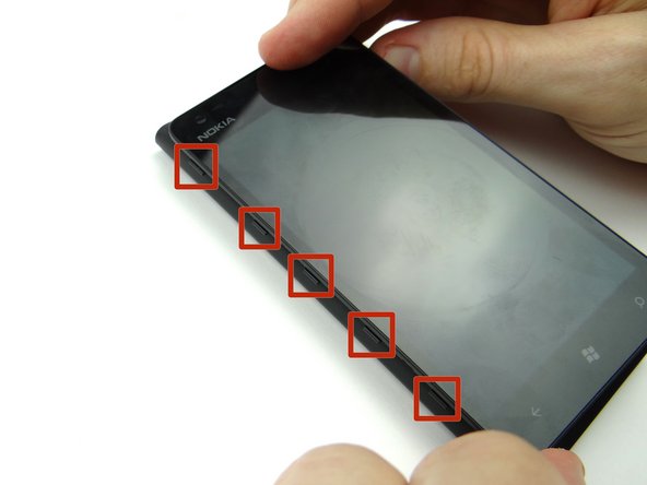
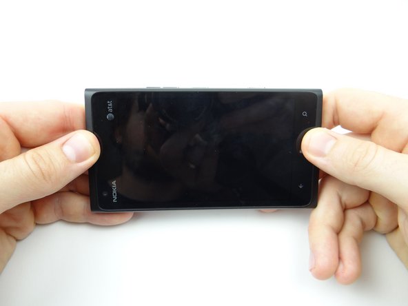
Picture 1: Align the clips on the left side of the screen with their slots on the rear case.
-
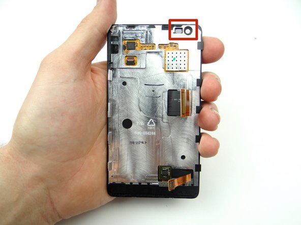
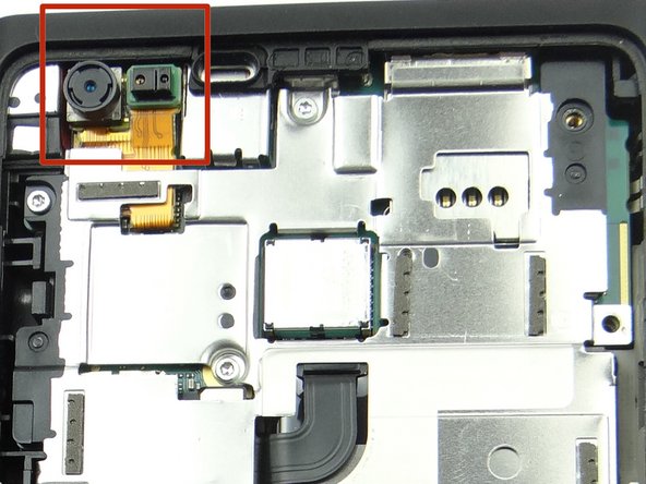
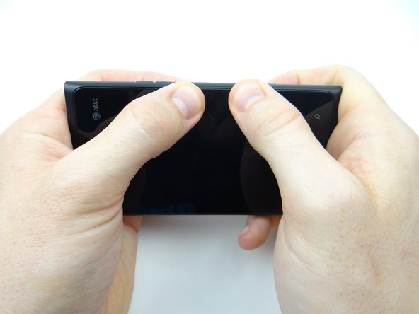
Picture 2: Use both hands to close the display on the rear case, guiding the front-facing camera and proximity sensor into their sockets.
-
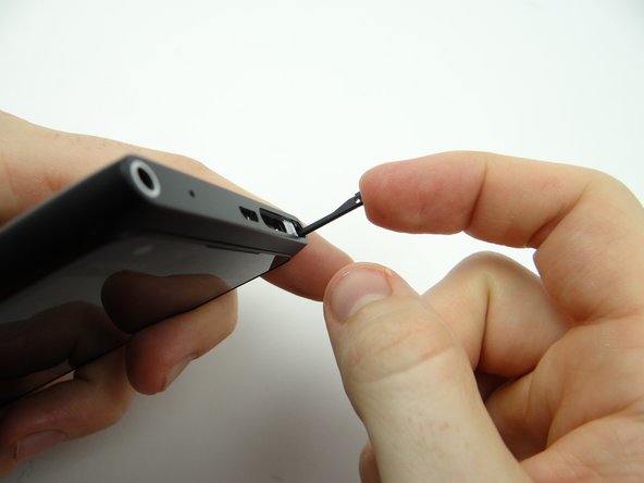
Picture 3: You may have to use the spudger to nudge the proximity sensor into place.
-