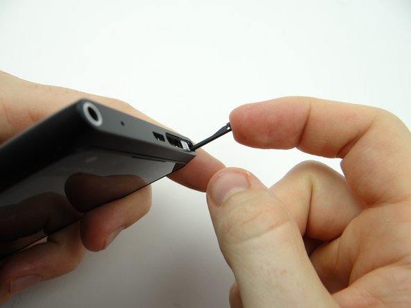
1. Push down on SIM card ejector slot with a paper clip to pop up the tray. Finish removing the SIM card tray with your fingers. Place SIM card and tray in COMPARTMENT A.
    • Push down on SIM card ejector slot with a paper clip to pop up the tray.

    • Finish removing the SIM card tray with your fingers.

    • Place SIM card and tray in COMPARTMENT A.

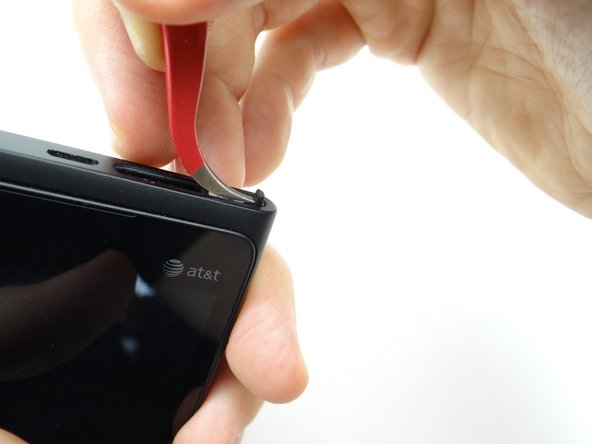
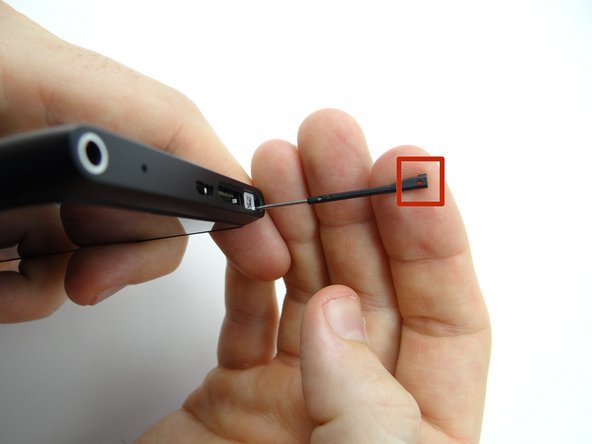
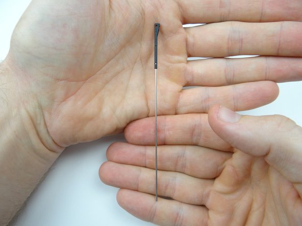
  2. Pictures 1 & 2: Use the curved tip tweezers to snag the tiny opening (red square in picture 2) on the screen locking pin.  Pull straight up until you can grab it with your fingers. Place locking pin in COMPARTMENT C. Place locking pin in COMPARTMENT C.
    • Pictures 1 & 2: Use the curved tip tweezers to snag the tiny opening (red square in picture 2) on the screen locking pin. Pull straight up until you can grab it with your fingers.

    • Place locking pin in COMPARTMENT C.

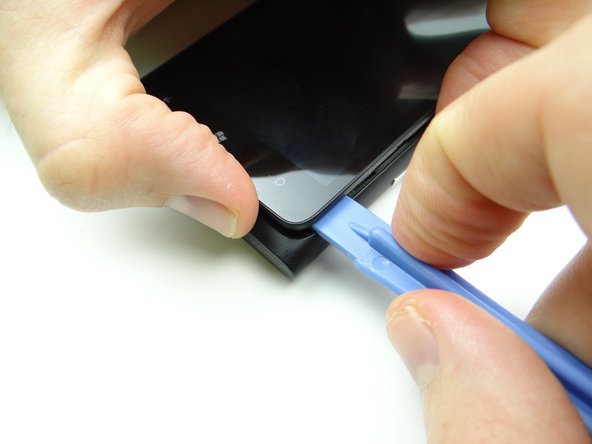
  3. In the next few steps you'll be releasing clips holding the display assembly to the rear panel:
    • In the next few steps you'll be releasing clips holding the display assembly to the rear panel:

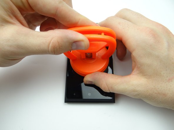
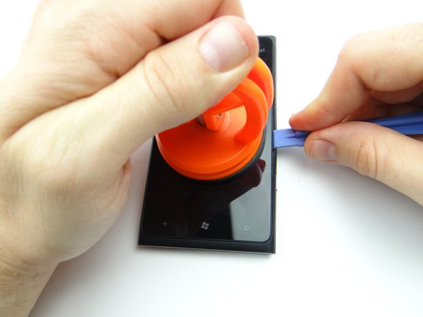
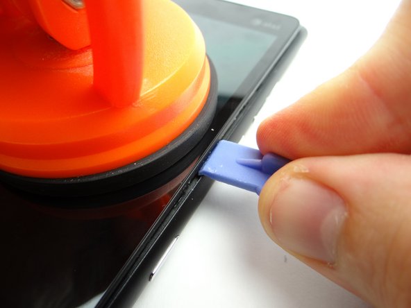
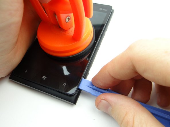
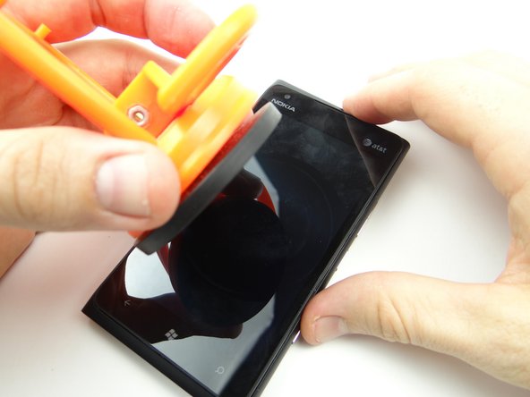
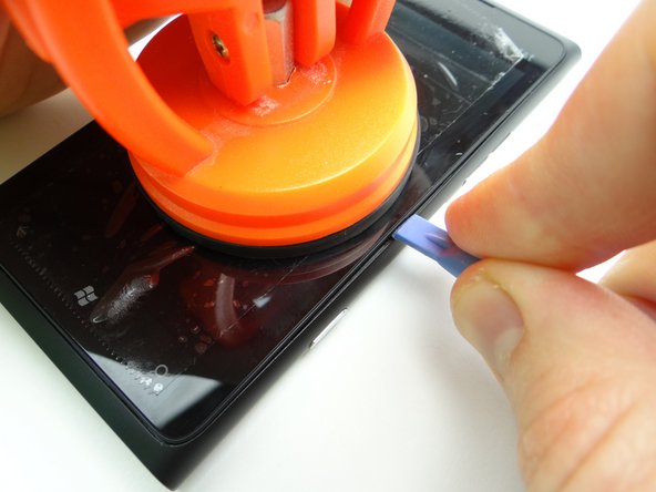
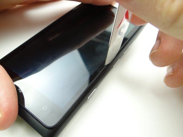
  4. Picture 1: Place a large suction cup in the center of the screen. Pictures 2 & 3: Pull up the screen slightly while wedging the blue pry tool in the center of the right side, between the display assembly bezel and rear case. Pictures 2 & 3: Pull up the screen slightly while wedging the blue pry tool in the center of the right side, between the display assembly bezel and rear case.
    • Picture 1: Place a large suction cup in the center of the screen.

    • Pictures 2 & 3: Pull up the screen slightly while wedging the blue pry tool in the center of the right side, between the display assembly bezel and rear case.

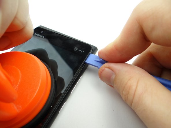
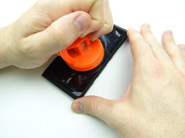
  5. Picture 1: Slowly work your way to the top with the blue pry tool while continuing to pull up gently with the suction cup. Picture 2: Work your way back down the right side. Picture 3: Remove the suction cup once the display moves freely.
    • Picture 1: Slowly work your way to the top with the blue pry tool while continuing to pull up gently with the suction cup.

    • Picture 2: Work your way back down the right side.

    • Picture 3: Remove the suction cup once the display moves freely.

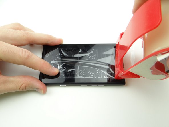
  6. Put packing tape over the screen to hold the broken pieces of glass together.  Smooth out the bubbles. Go back two steps to open the device OR use the iSesamo (shown in the next step) if the screen still won't budge. Go back two steps to open the device OR use the iSesamo (shown in the next step) if the screen still won't budge.
    • Put packing tape over the screen to hold the broken pieces of glass together. Smooth out the bubbles.

    • Go back two steps to open the device OR use the iSesamo (shown in the next step) if the screen still won't budge.

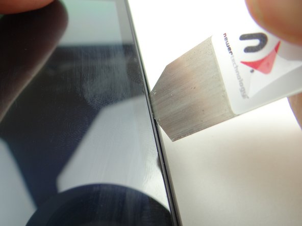
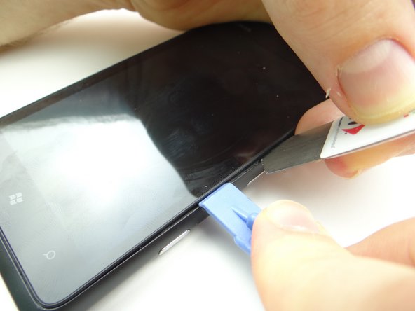
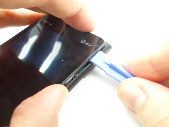
  7. If you can't create suction, use the iSesamo to pry open the screen: Pictures 1: Insert the tip of the iSesamo between the display assembly and rear panel. Only insert the iSesamo a couple millimeters as shown in Picture 2.
    • If you can't create suction, use the iSesamo to pry open the screen:

    • Pictures 1: Insert the tip of the iSesamo between the display assembly and rear panel.

    • Only insert the iSesamo a couple millimeters as shown in Picture 2.

    • Pictures 2 & 3: Use the iSesamo to pry open the device just enough to insert a wide blue pry tool face down.

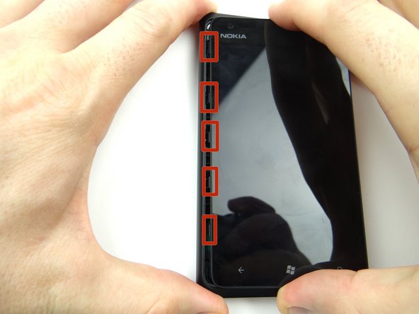
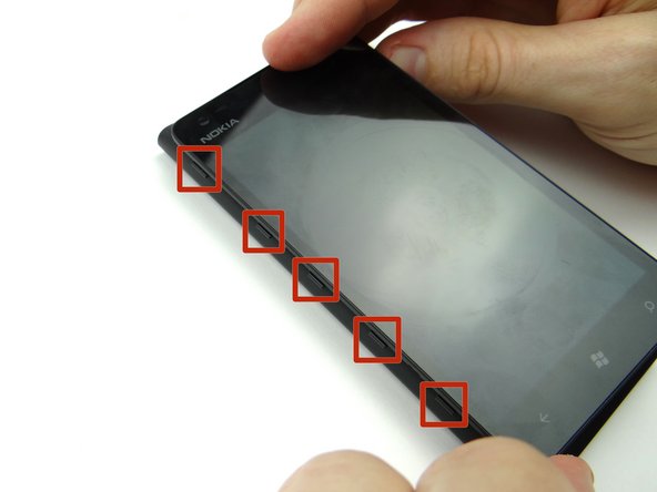
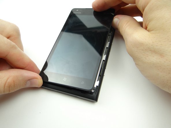
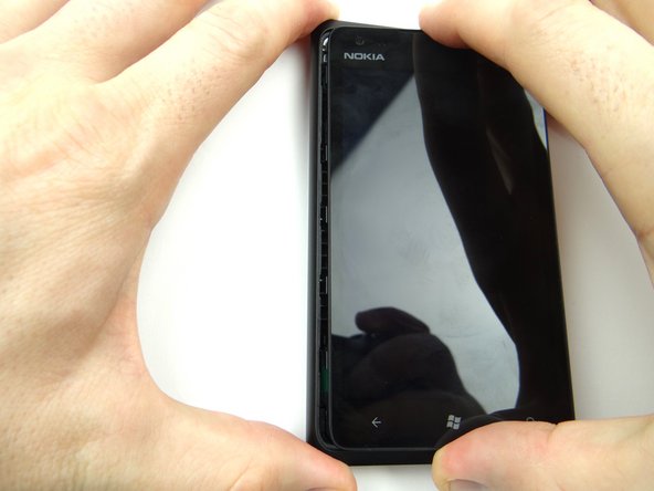
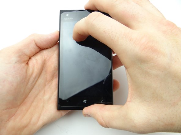
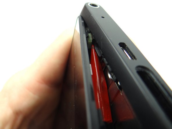
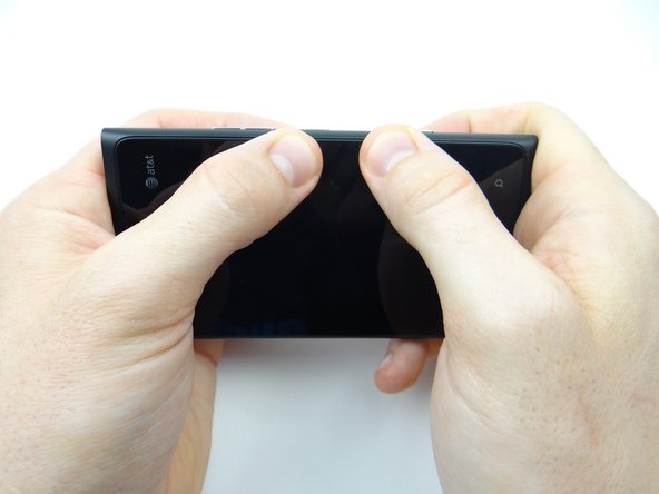
  8. Pinch the edges of the display as shown to avoid cuts if the screen is cracked. Work your way to the bottom of the display, freeing the clips from the rear panel.
    • Pinch the edges of the display as shown to avoid cuts if the screen is cracked.

    • Work your way to the bottom of the display, freeing the clips from the rear panel.

    • Work your way to the top while pulling up with your fingers until the display moves freely.

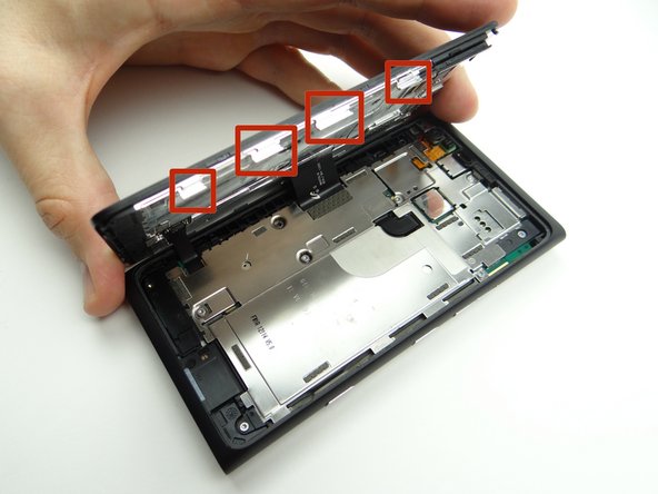
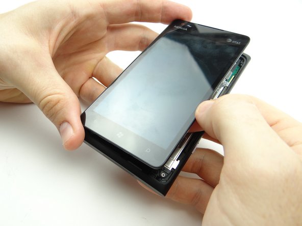
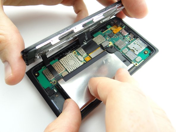
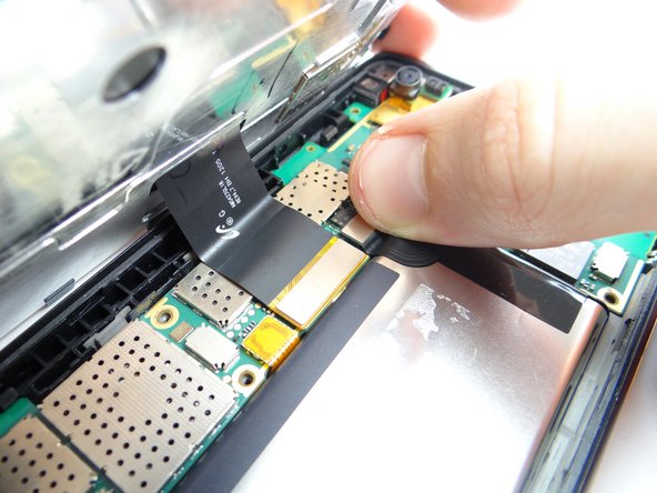
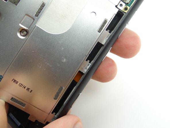
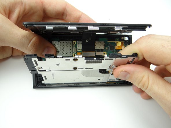
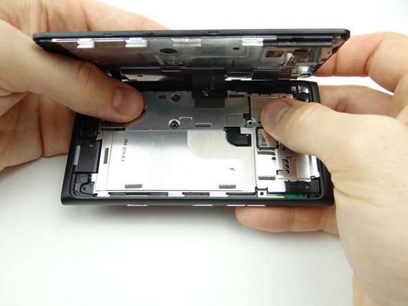
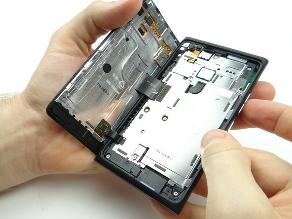
  9. Don't try to open the phone just yet - the front panel is attached by two cables that tear easily. Pictures 1 & 2: Lift screen up slightly.  Maneuver the clips on the left side over the top of the rear case.
    • Don't try to open the phone just yet - the front panel is attached by two cables that tear easily.

    • Pictures 1 & 2: Lift screen up slightly. Maneuver the clips on the left side over the top of the rear case.

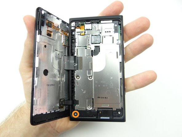
  10. Continue lifting the screen slowly until it reaches a 90° angle. Continue lifting the screen slowly until it reaches a 90° angle. Continue lifting the screen slowly until it reaches a 90° angle.
    • Continue lifting the screen slowly until it reaches a 90° angle.

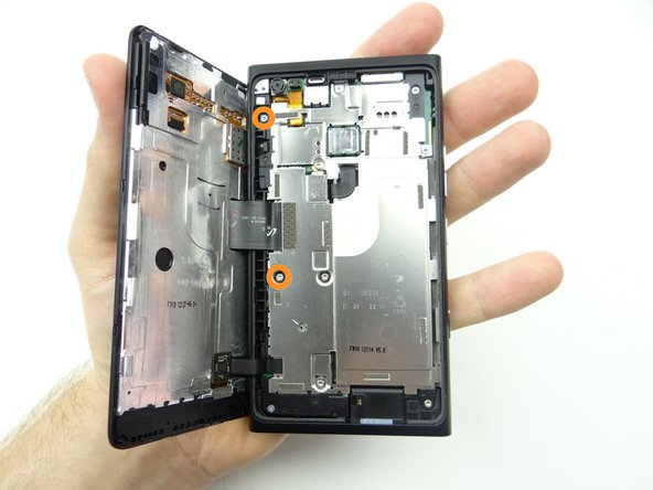
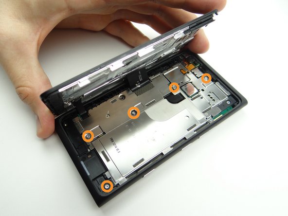
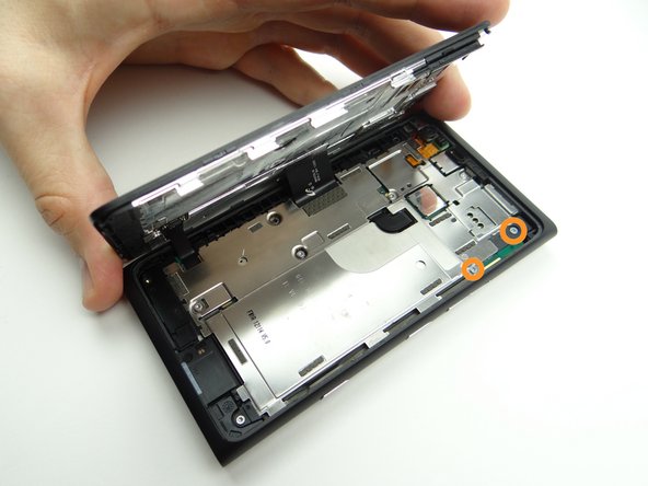
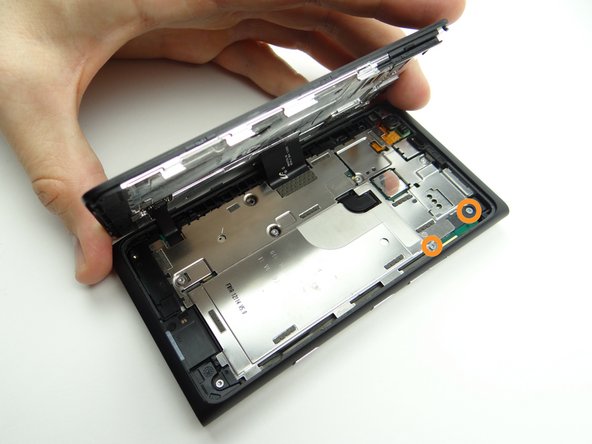
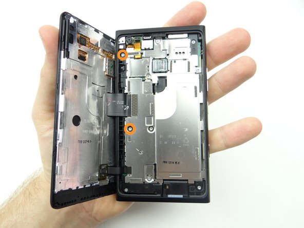
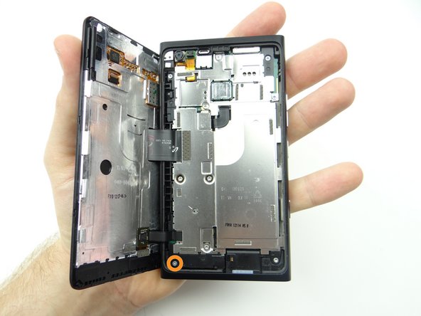
  11. Hold the phone in your hand as pictured while performing this step: Picture 1: Remove one 3.3 mm #00 Phillips screw.  Place in SLOT 1.
    • Hold the phone in your hand as pictured while performing this step:

    • Picture 1: Remove one 3.3 mm #00 Phillips screw. Place in SLOT 1.

    • Picture 2: Remove two 4.4 mm T5 Torx screws. Place in SLOT 2.

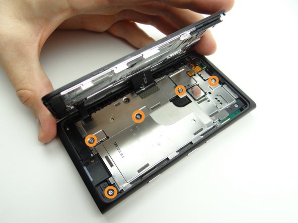
  12. Set phone on table while performing this step: Picture 1: Remove five 4.4 mm T5 Torx screws.  Place in SLOT 2. Picture 2: Remove two 3.3 mm #00 Phillips screws.  Place in SLOT 3.
    • Set phone on table while performing this step:

    • Picture 1: Remove five 4.4 mm T5 Torx screws. Place in SLOT 2.

    • Picture 2: Remove two 3.3 mm #00 Phillips screws. Place in SLOT 3.

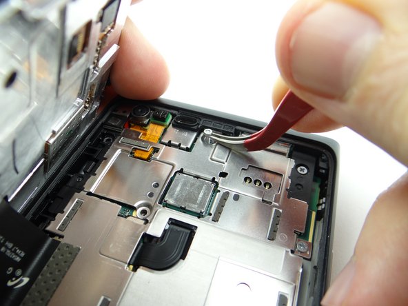
    • Picture 3: Use curved-tip tweezers to extract any screws that get caught.

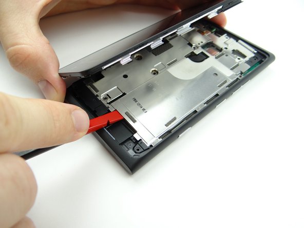
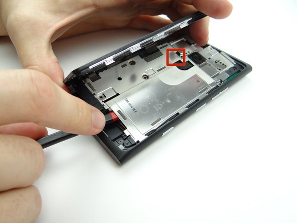
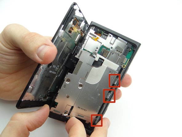
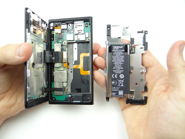
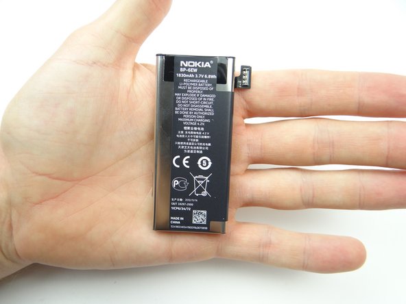
  13. The battery is adhered to the underside of the mid-plate and should come up with it (as shown in the next step). Picture 1: Wedge the flat end of the spudger under the mid-plate exactly where shown. Picture 2: Lift from the top and bottom taking care not to torque the battery connector (red square in Picture 2).
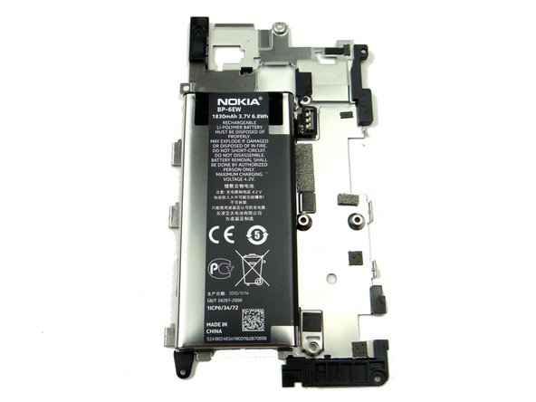
    • The battery is adhered to the underside of the mid-plate and should come up with it (as shown in the next step).

    • Picture 1: Wedge the flat end of the spudger under the mid-plate exactly where shown.

    • Picture 2: Lift from the top and bottom taking care not to torque the battery connector (red square in Picture 2).

    • Picture 3: Guide the clips on the mid-plate free from the rear case.

  14. Place components on the anti-static foam.
    • Place components on the anti-static foam.

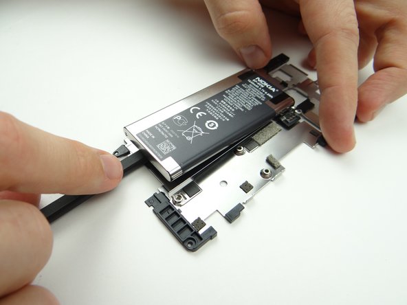
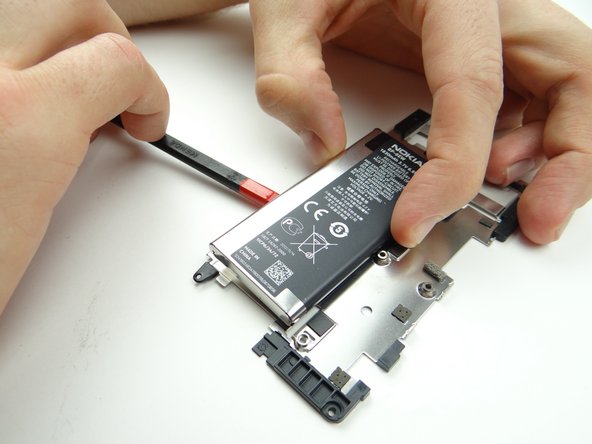
  15. Wedge the flat end of the spudger at the center-bottom of the battery.  Push halfway up. Turn the spudger to cut through the adhesive holding the battery. Turn the spudger to cut through the adhesive holding the battery.
    • Wedge the flat end of the spudger at the center-bottom of the battery. Push halfway up.

    • Turn the spudger to cut through the adhesive holding the battery.

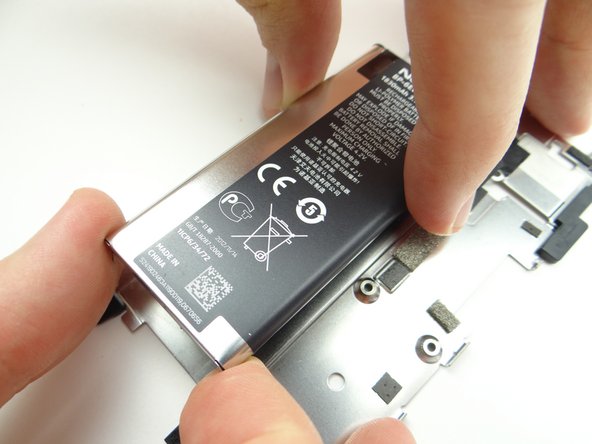
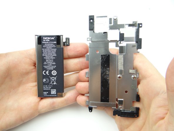
  16. Continue removing the battery with your fingers. Place the battery and mid-plate on the anti-static foam.
    • Continue removing the battery with your fingers.

    • Place the battery and mid-plate on the anti-static foam.

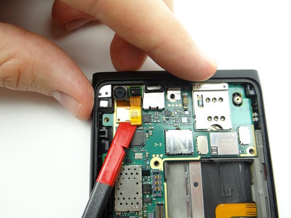
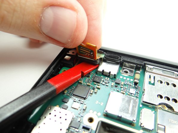
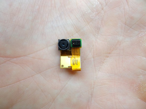
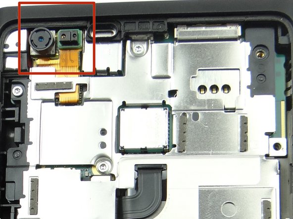
  17. Use the flat end of the spudger to disconnect front-facing camera & proximity sensor assembly. Peel assembly away from rear case with your fingers.  Slide flat end of spudger under assembly to push through the mild adhesive holding it down. Place assembly in COMPARTMENT B.
    • Use the flat end of the spudger to disconnect front-facing camera & proximity sensor assembly.

    • Peel assembly away from rear case with your fingers. Slide flat end of spudger under assembly to push through the mild adhesive holding it down.

    • Place assembly in COMPARTMENT B.

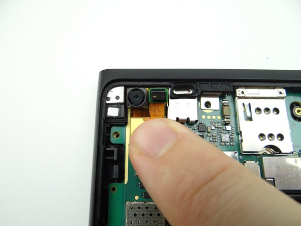
  18. From COMPARTMENT B, replace front-facing camera & proximity sensor assembly. Seat the cable, but don't push the proximity sensor into place.
    • From COMPARTMENT B, replace front-facing camera & proximity sensor assembly.

    • Seat the cable, but don't push the proximity sensor into place.

    • Leave some play so you can maneuver the proximity sensor into its socket on the display when you're closing the device.

  19. Seat the battery and connect it to the logic board. Seat the battery and connect it to the logic board. Seat the battery and connect it to the logic board.
    • Seat the battery and connect it to the logic board.

  20. Seat the mid-plate clips in the rear case. Seat the mid-plate clips in the rear case.
    • Seat the mid-plate clips in the rear case.

  21. Picture 1: Push mid-plate into place. Picture 2: Replace two 3.3 mm #00 Phillips screws from SLOT 3. Picture 3: Replace five 4.4 mm T5 Torx screws from SLOT 2.
    • Picture 1: Push mid-plate into place.

    • Picture 2: Replace two 3.3 mm #00 Phillips screws from SLOT 3.

    • Picture 3: Replace five 4.4 mm T5 Torx screws from SLOT 2.

  22. Hold the phone in your hand as pictured while performing this step: Picture 1: Replace two 4.4 mm T5 Torx screws from SLOT 2.
    • Hold the phone in your hand as pictured while performing this step:

    • Picture 1: Replace two 4.4 mm T5 Torx screws from SLOT 2.

    • Picture 2: Replace one 3.3 mm #00 Phillips screw from SLOT 1.

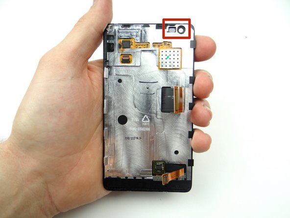
  23. It may take some fiddling to get the front-facing camera & proximity sensor assembly properly seated in the display sockets (red square) as you close the device over the next few steps. It may take some fiddling to get the front-facing camera & proximity sensor assembly properly seated in the display sockets (red square) as you close the device over the next few steps.
    • It may take some fiddling to get the front-facing camera & proximity sensor assembly properly seated in the display sockets (red square) as you close the device over the next few steps.

  24. Picture 1: Align the clips on the left side of the screen with their slots on the rear case. Picture 2: Use both hands to close the display on the rear case, guiding the front-facing camera and proximity sensor into their sockets. Picture 3: You may have to use the spudger to nudge the proximity sensor into place.
    • Picture 1: Align the clips on the left side of the screen with their slots on the rear case.

    • Picture 2: Use both hands to close the display on the rear case, guiding the front-facing camera and proximity sensor into their sockets.

    • Picture 3: You may have to use the spudger to nudge the proximity sensor into place.

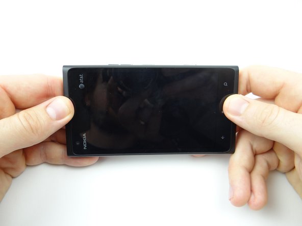
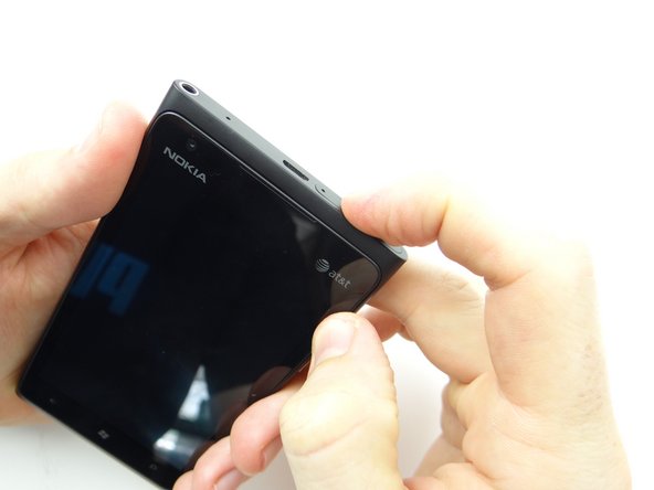
  25. Squeeze the top and bottom of the display into place Squeeze the buttons side into place.
    • Squeeze the top and bottom of the display into place

    • Squeeze the buttons side into place.

  26. Replace screen locking pin from COMPARTMENT C. Replace SIM card and tray from COMPARTMENT A. Power up and test device.
    • Replace screen locking pin from COMPARTMENT C.

    • Replace SIM card and tray from COMPARTMENT A.

    • Power up and test device.

Finish Line
James Linder

Member since: 01/24/2013

71,591 Reputation

217 Guides authored

0 Comments

Add Comment

View Statistics:

Past 24 Hours: 0

Past 7 Days: 0

Past 30 Days: 0

All Time: 25

CELL PHONE SANDBOX