-
-
Before disassembly, thoroughly wash and dry your hands.
-
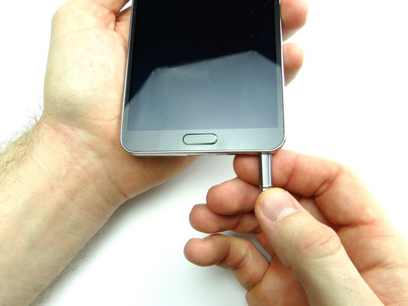
Remove the stylus, battery cover and battery. Place in ZONE I.
-
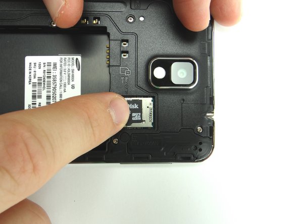
Remove SIM card and SD card. Place in COMPARTMENT A.
-
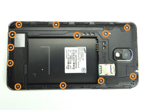
Remove twelve 4.0 mm #00 Phillips screws. Place in SLOT 1.
-
-
-
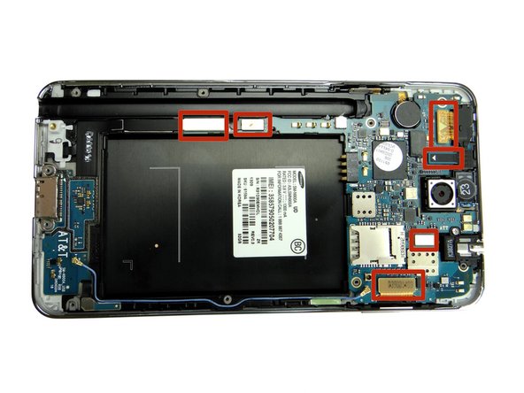
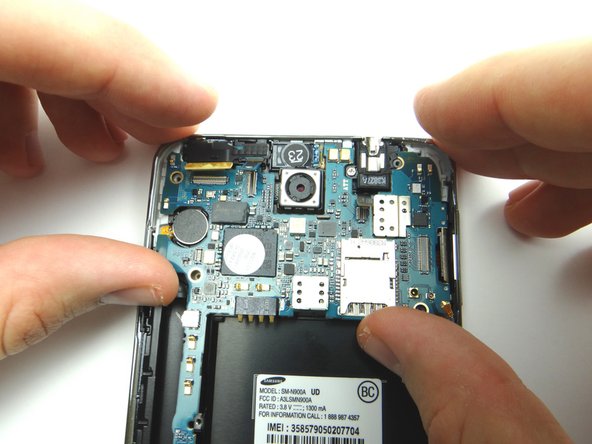
Use the Blue Pry Tool to disconnect six ribbon cable connectors on the logic board.
-
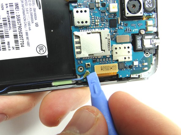
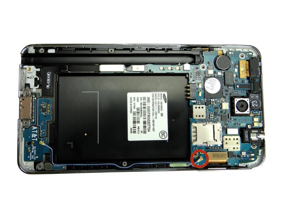
Disconnect the antenna cable using the blue pry tool as shown in Picture 2.
-
-
-
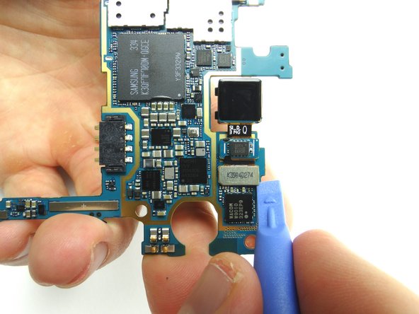
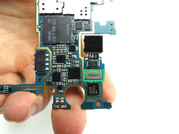
Remove rear-facing camera from underside of logic board. Place in COMPARTMENT B.
-
-
-
From COMPARTMENT B, replace rear-facing camera on underside of logic board
-
-
-
Replace the logic board from ZONE III. Make sure no cables are trapped underneath the logic board.
-
Reseat six cables.
-
Reseat antenna.
-
-
-
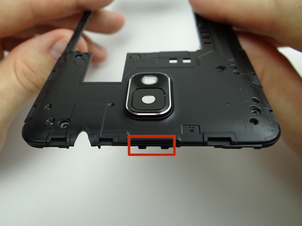
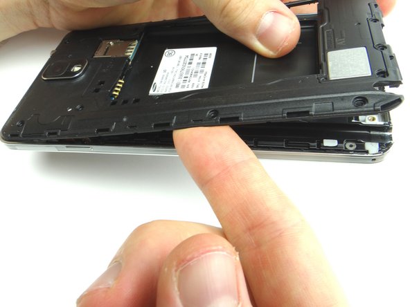
Replace mid-frame from ZONE II. Note the clips at the top of the mid-frame.
-
Place the mid-frame clips in their slots at the top of the front panel before seating the rest of the mid-frame.
-