Parts
No parts specified.
-
-
Before disassembling the Samsung Galaxy S3, thoroughly wash and dry your hands.
-
Picture 1: Remove battery cover and battery. Place into ZONE I.
-
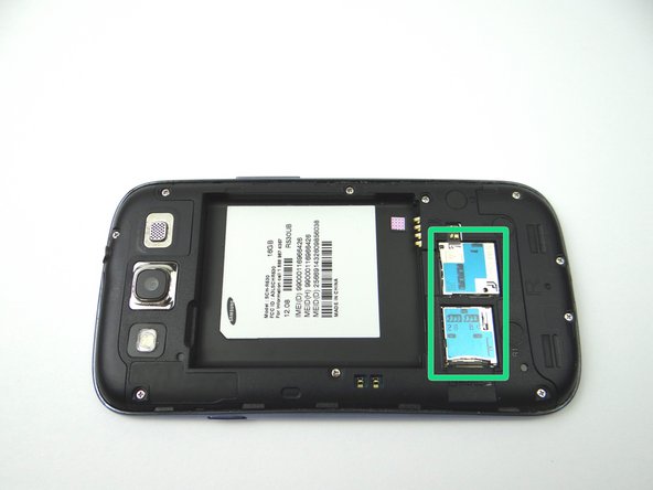
Picture 2: Remove SIM card, and SD card. Place in COMPARTMENT A.
-
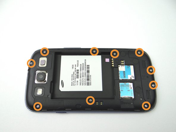
Picture 3: Remove ten 4.0 mm Phillips screws. Place in SLOT 1.
-
-
-
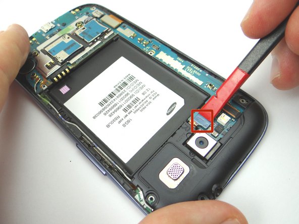
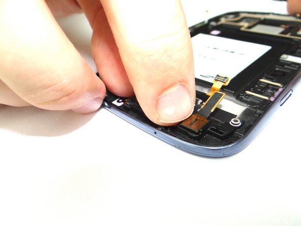
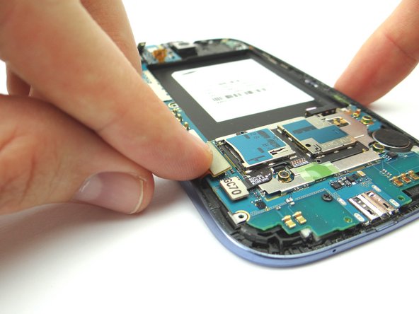
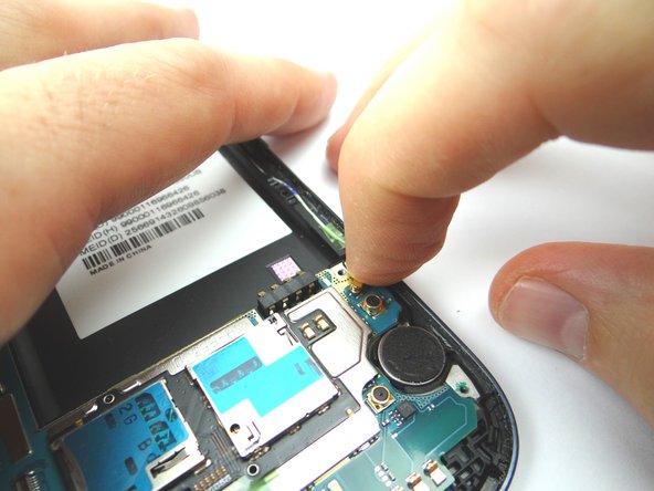
Picture 1: Use the Black Spudger to release the headphone jack/speaker assembly cable.
-
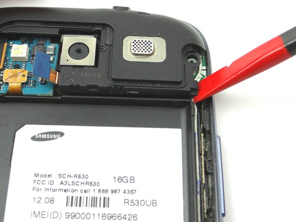
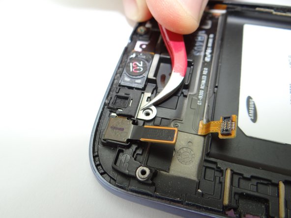
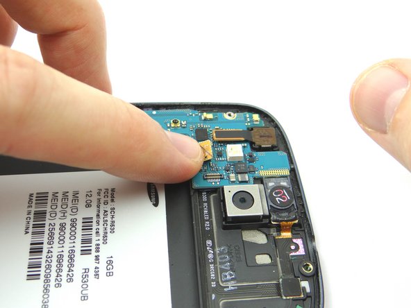
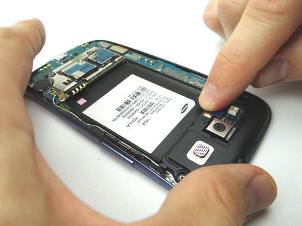
Picture 2: Place the flat tip of the Black Spudger in the bottom right corner of the headphone jack/speaker assembly and gently pry up to release it from the phone.
-
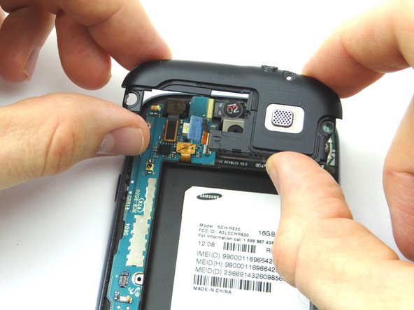
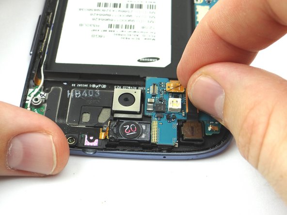
Picture 3: Place headphone jack/speaker assembly into ZONE III.
-
-
-
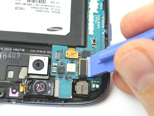
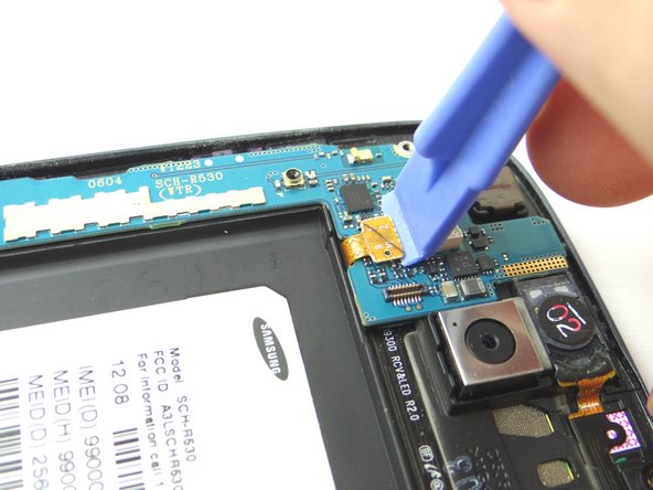
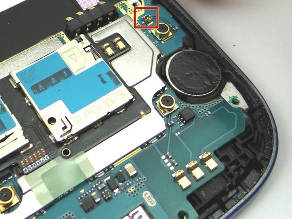
Picture 1: Use the Blue Pry Tool to release the front-facing camera cable.
-
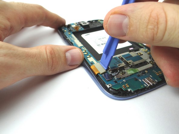
Picture 2: Use the Blue Pry Tool to release the earpiece speaker/volume button cable connector.
-
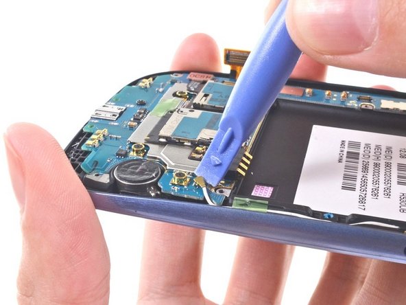
Picture 3: Use the Blue Pry Tool to release the display assembly cable connecter.
-
-
-
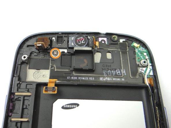
Picture 1: Remove one 2.0 mm Phillips screw and place into SLOT 3.
-
Picture 2: Remove the top microphone casing bracket and place into SLOT 3.
-
-
-
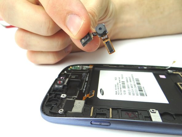
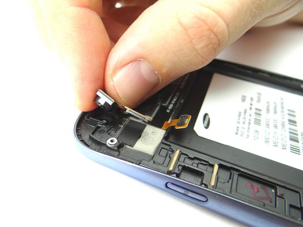
Picture 1 & 2: Replace the front-facing camera from COMPARTMENT B.
-
Picture 3: Replace the top microphone casing bracket from SLOT 3.
-
-
-
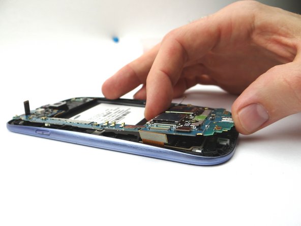
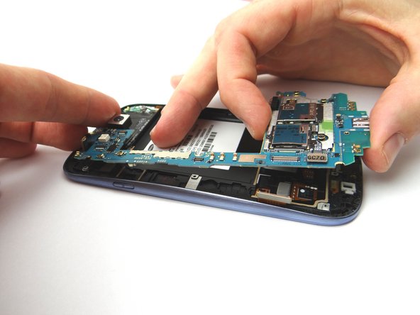
Picture 1 & 2: Place the logic board onto the phone from ZONE IV.
-
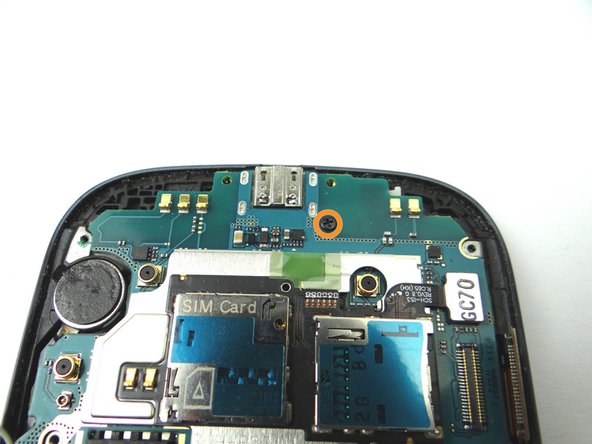
Picture 3: Replace one 3.0 mm screw from SLOT 2.
-
-
-
Picture 1: Replace headphone jack/speaker assembly from ZONE III.
-
Picture 2: Use your finger to reattach the headphone jack/speaker assembly cable.
-
-
-
Picture 1 & 2: Replace the mid-frame on the phone from ZONE II.
-
Picture 2: Replace ten 4.0 mm Phillips screws from SLOT 1.
-