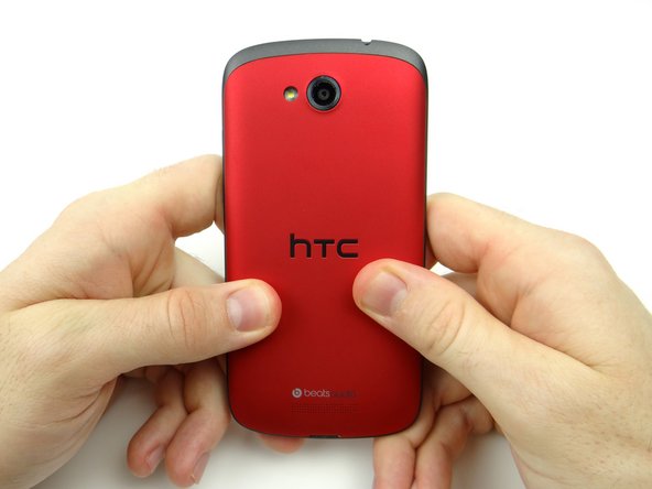
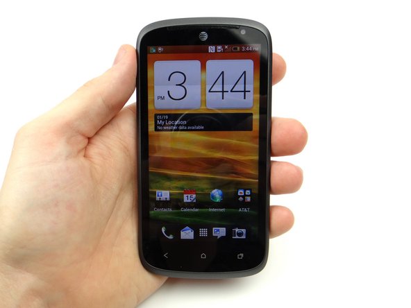
-
-
Power down the device.
-
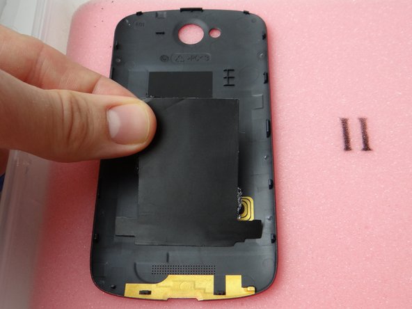
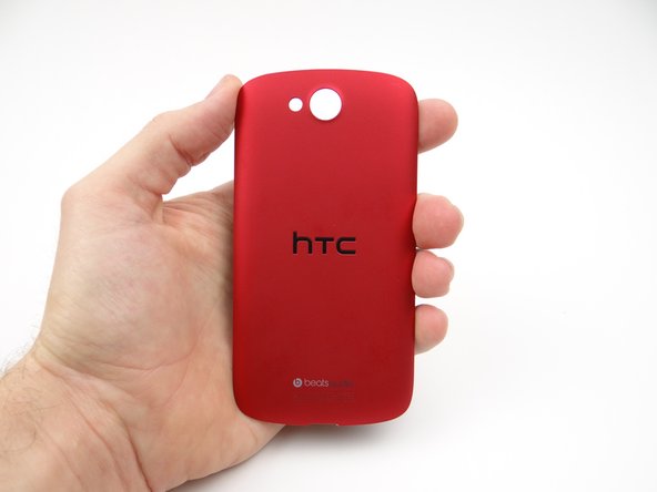
Remove the battery cover and place it in ZONE I.
-
-
-
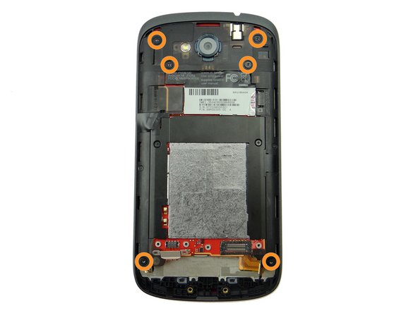
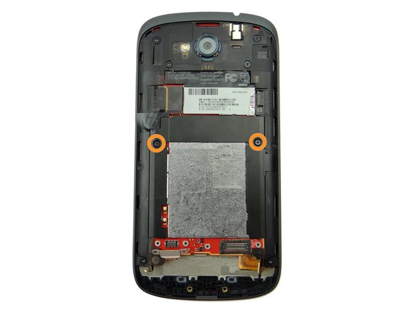
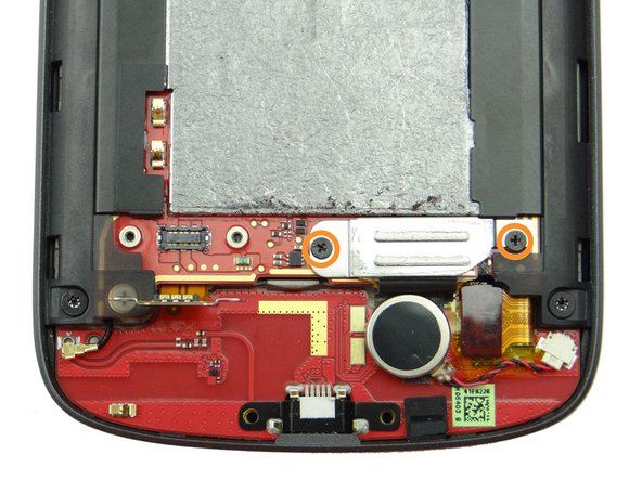
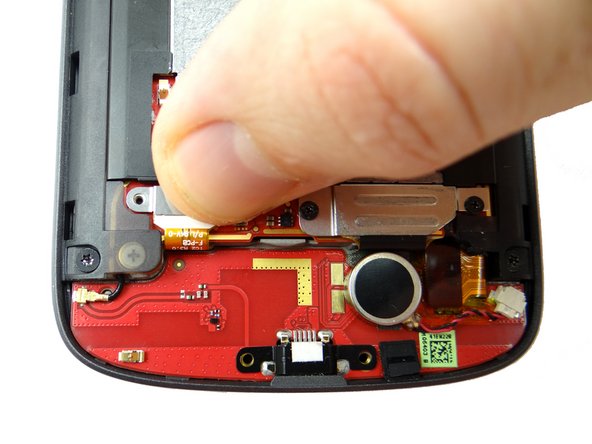
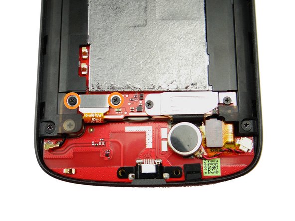
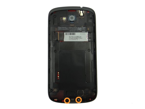
Remove two 3.6 mm T4 Torx screws. Place them in SLOT 1.
-
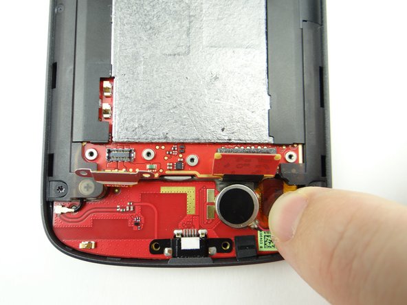
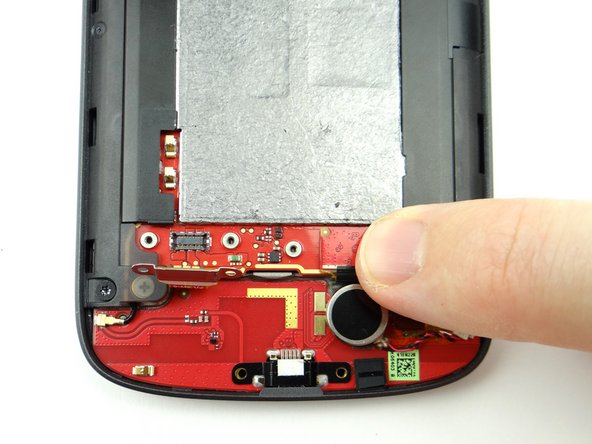
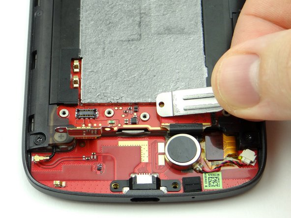
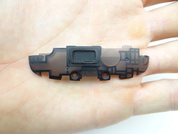
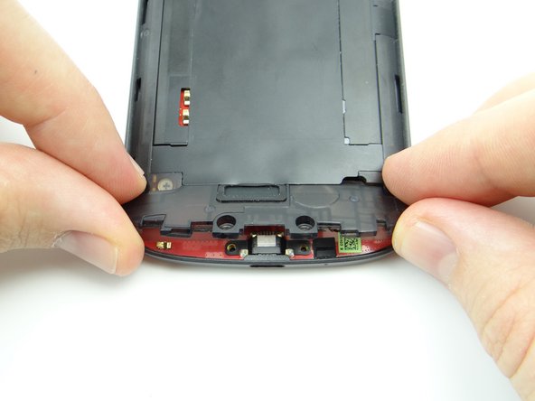
Use the pointed end of the spudger to pry up the speaker assembly. Remove it with your fingers and place it in ZONE I (below battery cover).
-
-
-
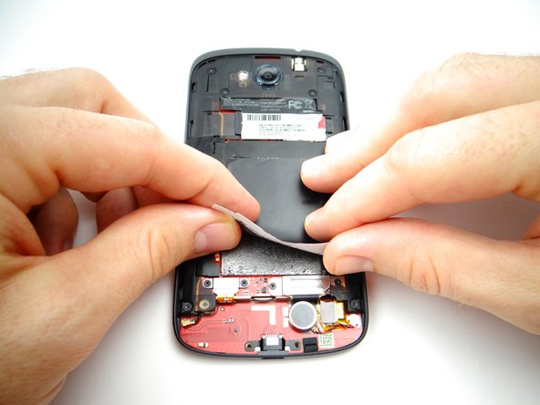
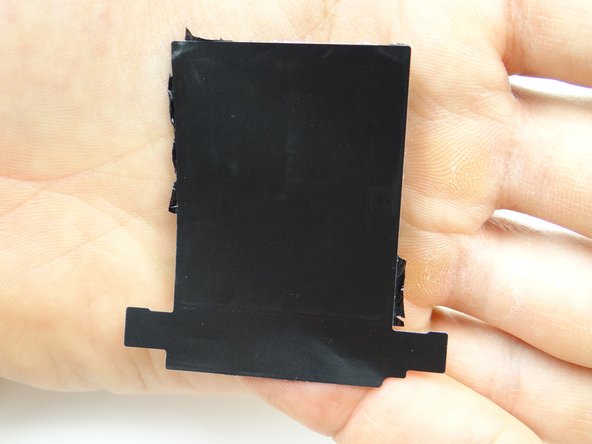
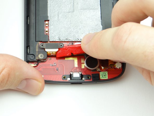
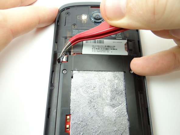
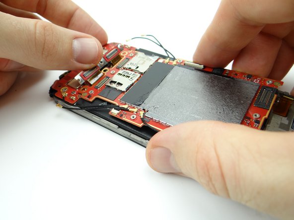
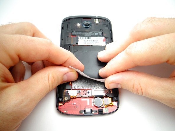
Peel up the tape covering the logic board.
-
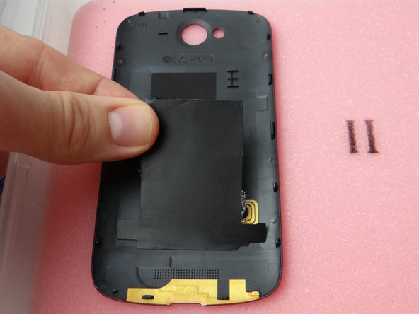
Place it on the inside of the battery cover in ZONE I, sticky side down.
-
-
-
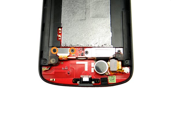
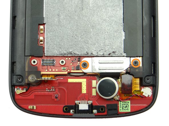
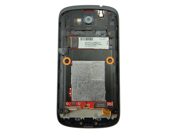
Picture 1: Remove two 1.8 mm #00 Phillips screws. Place in SLOT 3.
-
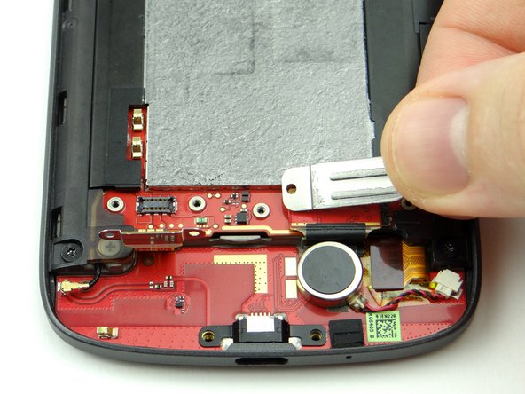
Picture 2: Remove the shield held down by the screws and place it in SLOT 3 (with the screws).
-
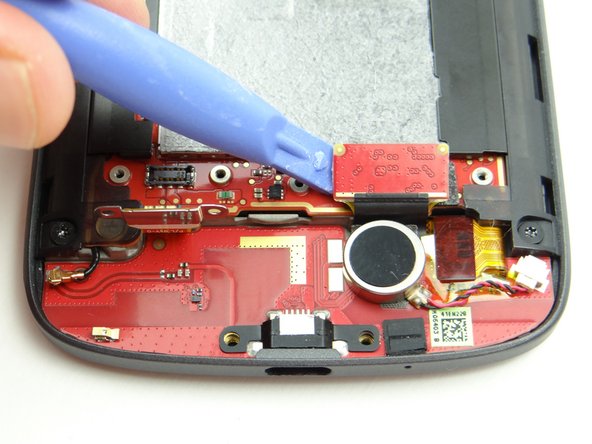
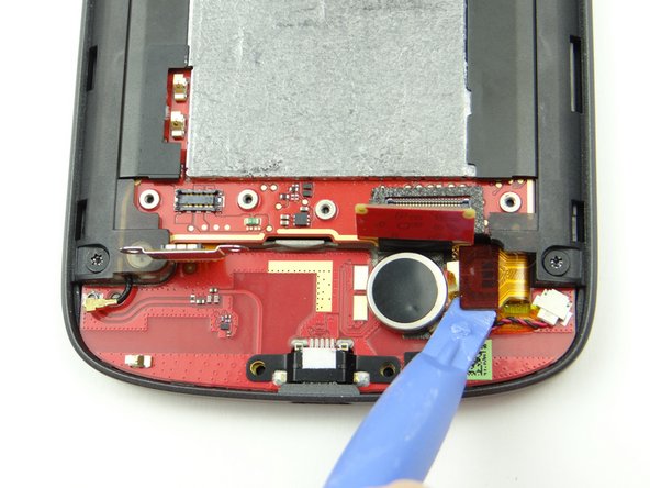
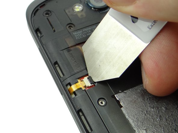
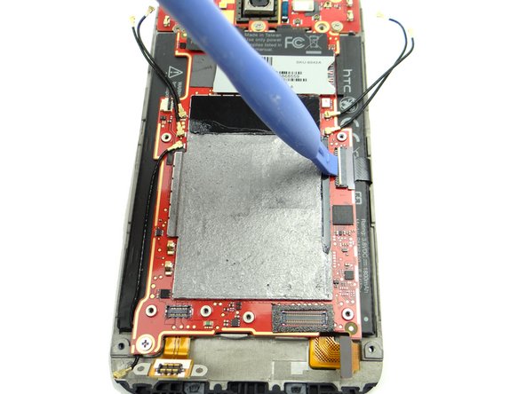
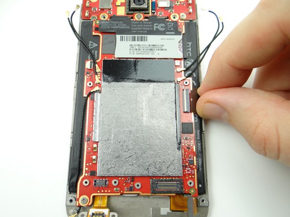
Use blue pry tool to disconnect charging port daughter board cable.
-
-
-
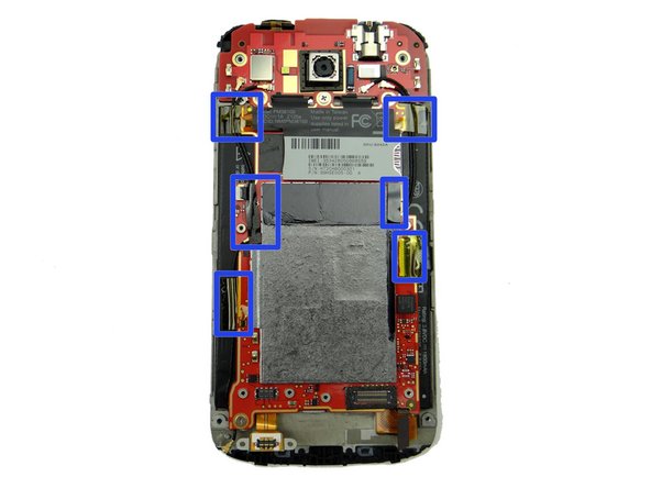
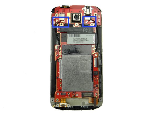
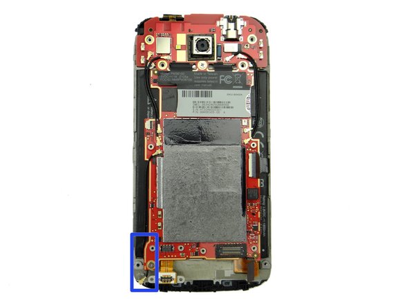
Picture 1: Remove the Kapton tape and electrical tape outlined in the blue rectangles.
-
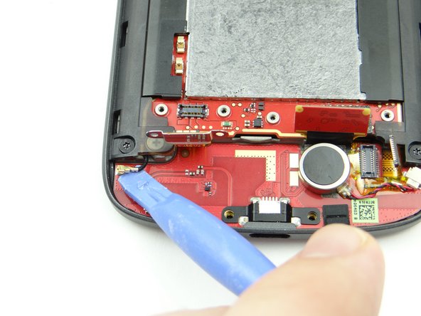
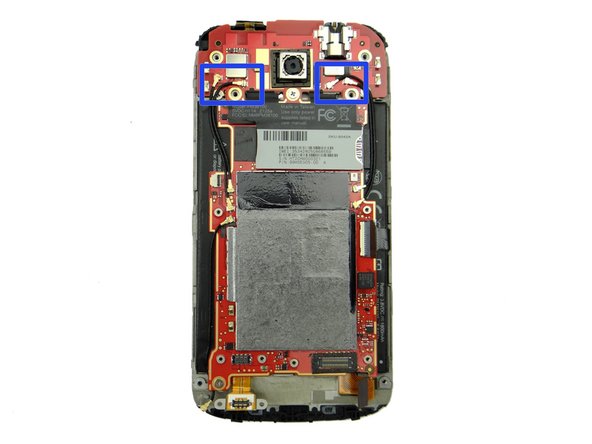
Picture 2: Use the blue pry tool to disconnect the four antenna cables from the daughter board.
-
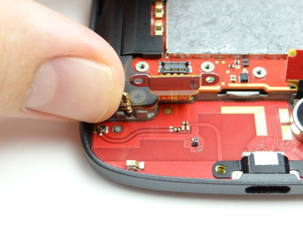
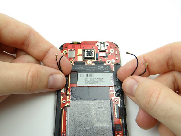
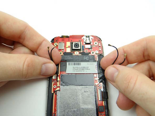
Picture 3: Gently bend the four cables away from the upper logic board.
-
-
-
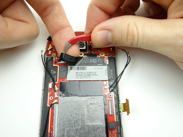
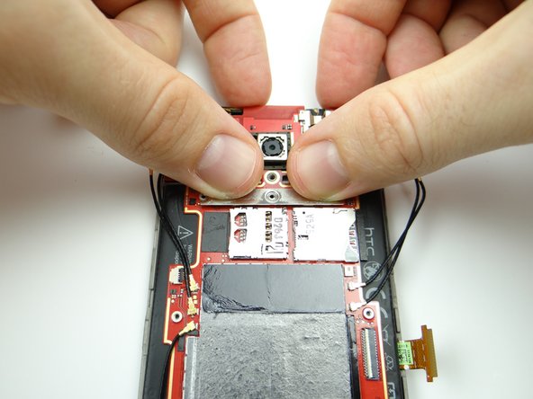
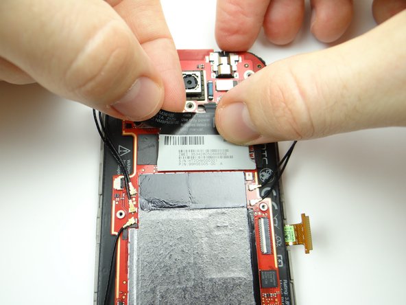
Picture 1: Take care not to touch the logic board as you pinch the upper-left corner of the IMEI sticker with curved tip tweezers. Peel it up until you can wedge your finger under the sticker.
-
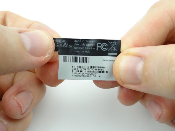
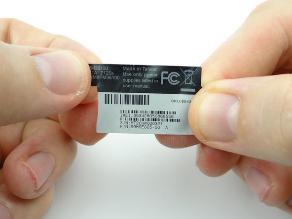
Picture 2: Continue peeling up the sticker with your fingers. Place the IMEI sticker against the wall of compartment D.
-
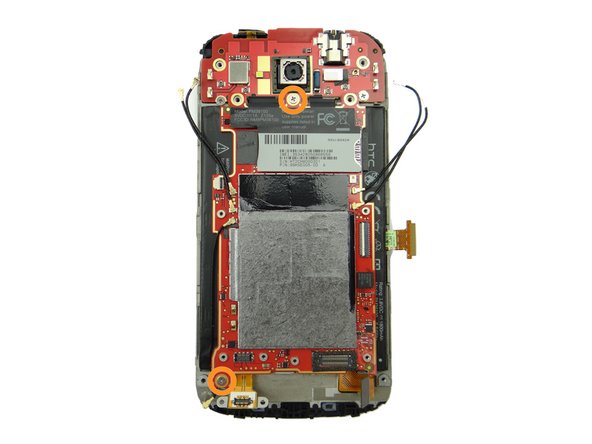
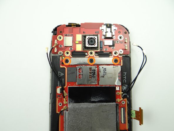
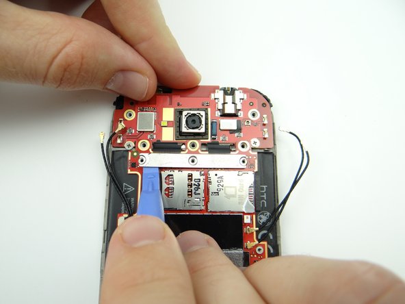
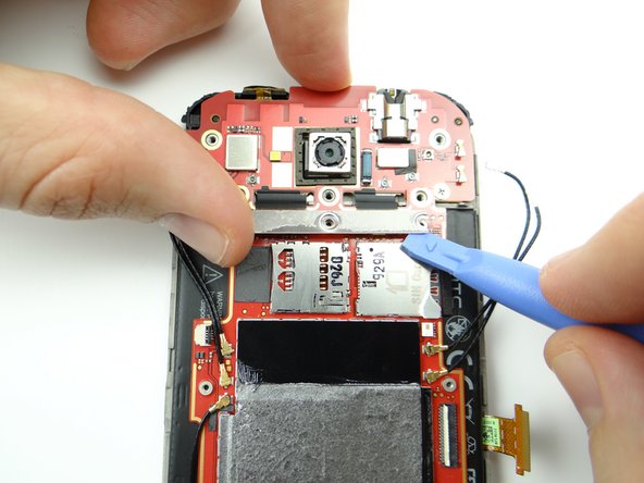
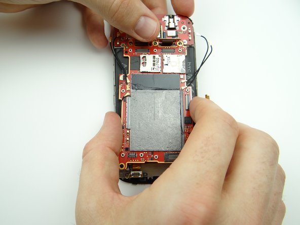
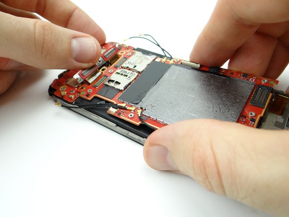
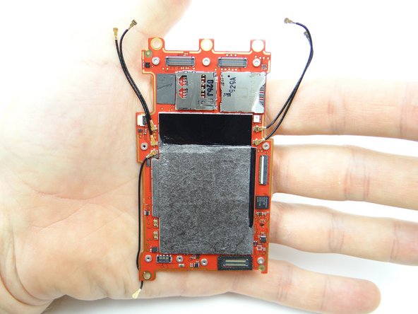
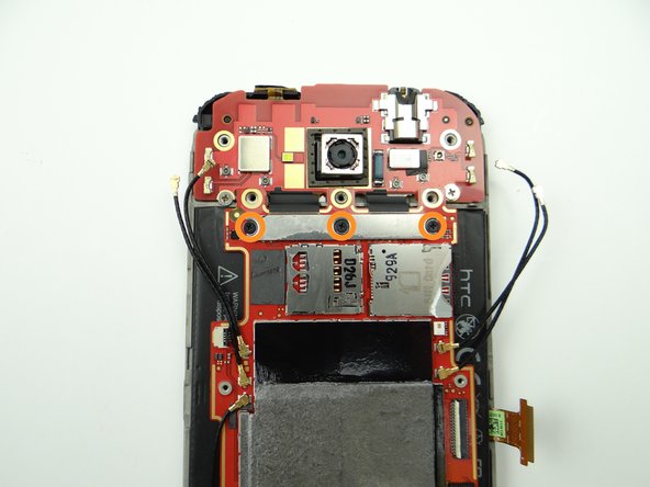
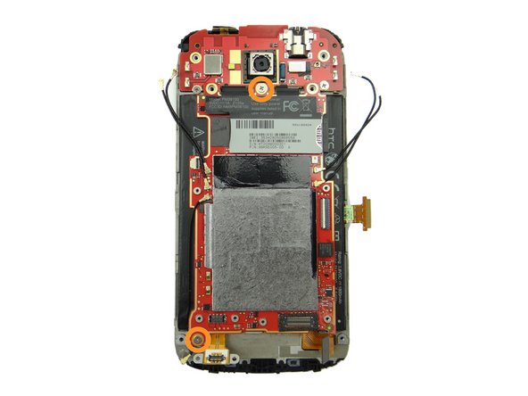
Picture 3: Remove three 1.6 mm #00 Phillips screws holding upper logic board to main logic board. Place in SLOT 5.
-
-
-
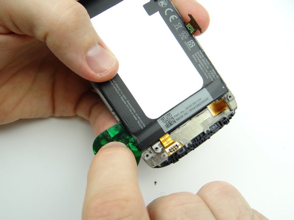
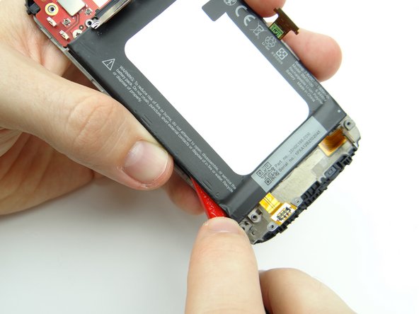
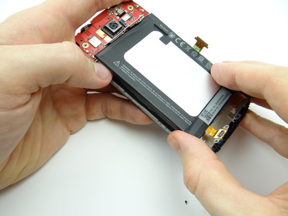
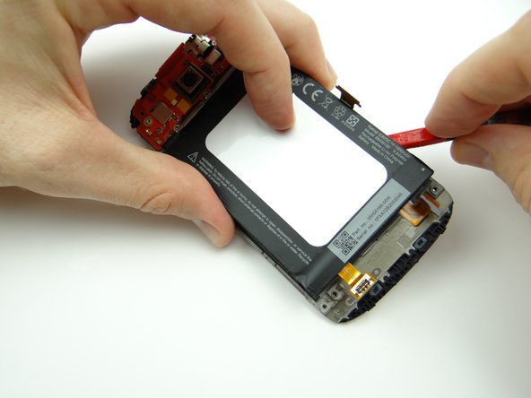
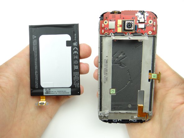
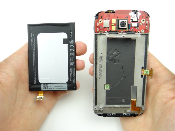
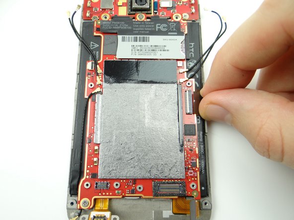
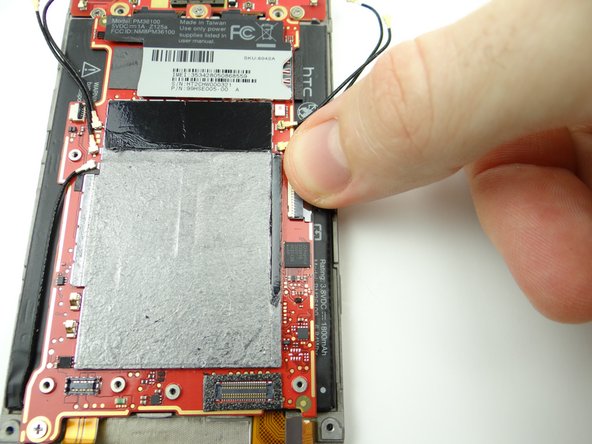
Strong adhesive runs the length of the battery on either side, holding it to the front panel. Additionally, there's a circuit board at the bottom of the battery. Take extra care to avoid bending the circuit board:
-
Picture 1: Use a guitar pick to push under the lower-left corner of the battery to cut through the adhesive.
-
Picture 2: Wedge the flat end of the spudger where you inserted the guitar pick. Work your way up the left side to separate the adhesive
-
Picture 3: Use your thumbs to lift the left side of the battery slightly.
-
-
-
Replace the battery from ZONE IV:
-
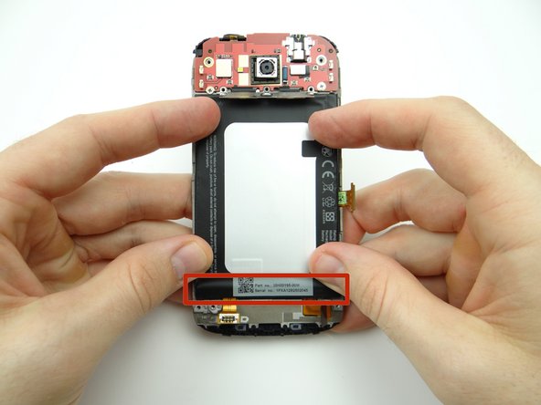
Avoid the circuit board (red rectangle) while firmly pushing the battery into place.
-
-
-
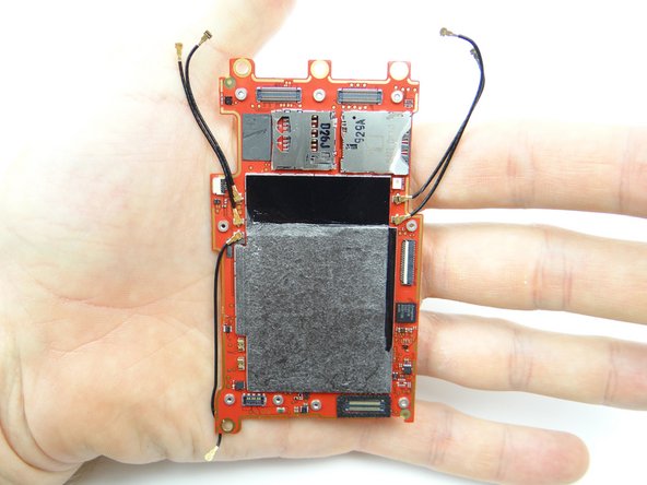
Retrieve logic board from ZONE III:
-
Hold connector cable on upper logic board out of the way while seating logic board.
-
Seat silver upper logic board connector cable on main logic board.
-
-
-
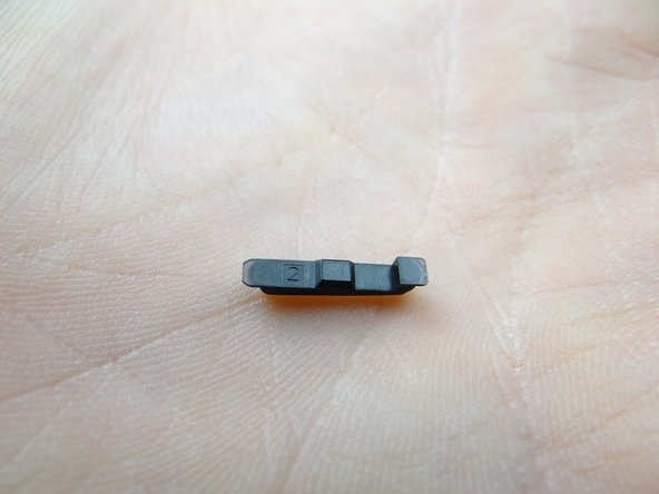
Retrieve the power button from COMPARTMENT B.
-
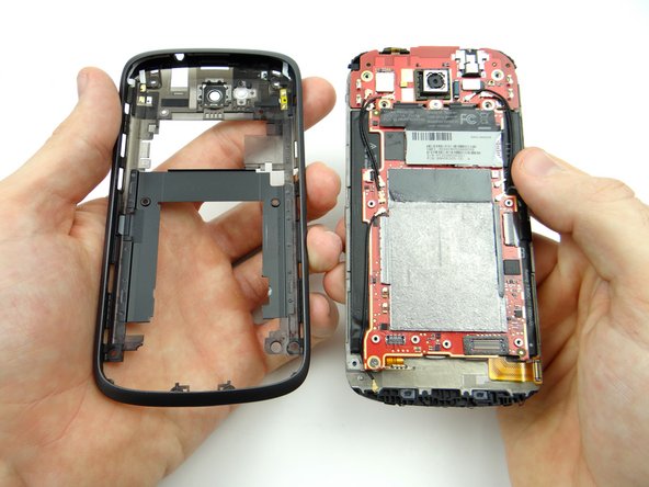
Retrieve the mid-body from ZONE II and turn it upside down:
-
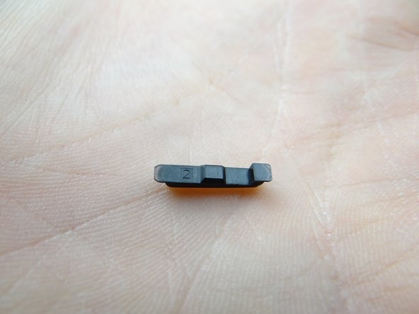
Seat the power button in the mid-body using the orientation pictured.
-
-
-
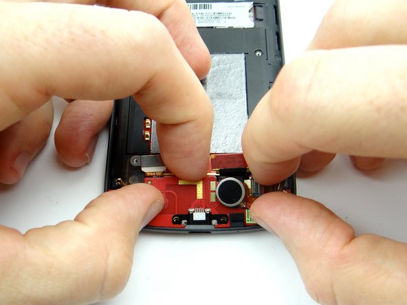
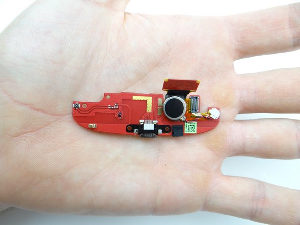
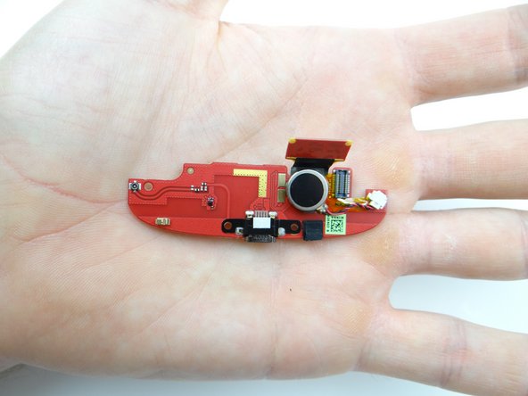
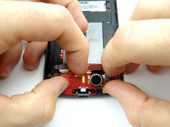
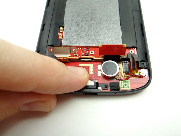
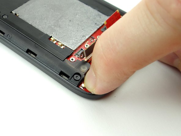
Retrieve charging port board from ZONE II.
-
-
-
Seat battery connector.
-
Replace two 1.7 mm #00 Phillips screws from SLOT 2 to secure battery connector.
-
-
-
Replace speaker assembly from ZONE I:
-
Position top edge first then push speaker assembly fully into place.
-
Replace two 3.6 mm T4 Torx screws from SLOT 1 to secure speaker assembly.
-
-
-
Seat battery cover from ZONE I.
-
Power up and test device.
-
Almost done!
Finish Line


