-
-
Power down device.
-
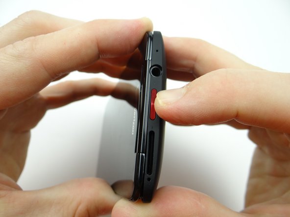
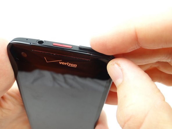
Push down on SIM card ejector slot with a paper clip to pop up the tray.
-
Finish removing the SIM card tray with your fingers. Place SIM card and tray in COMPARTMENT A.
-
-
-
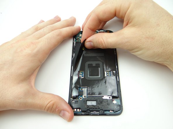
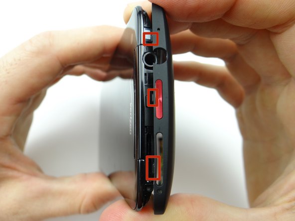
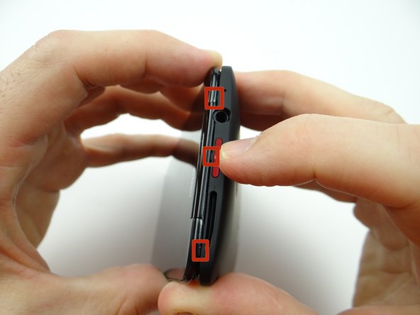
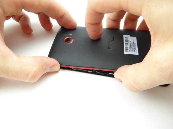
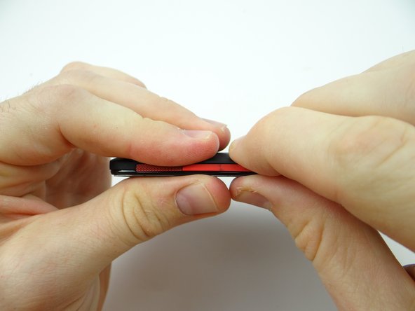
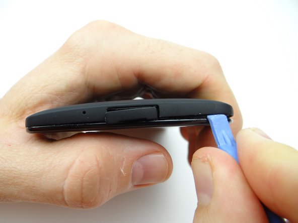
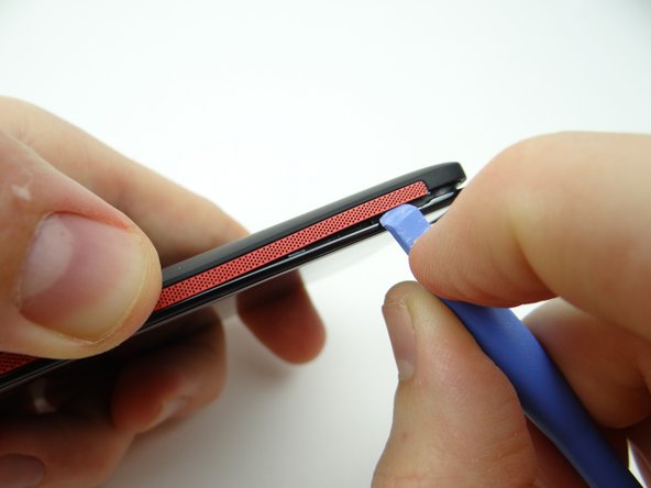
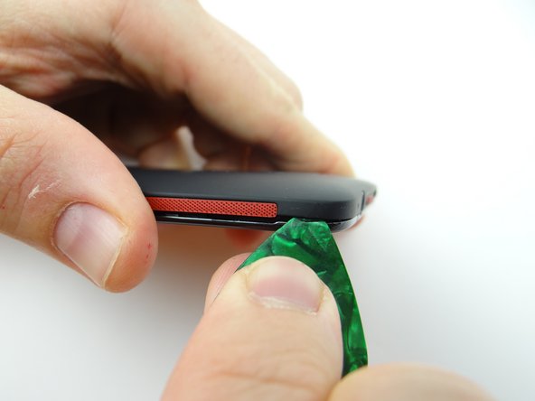
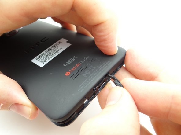
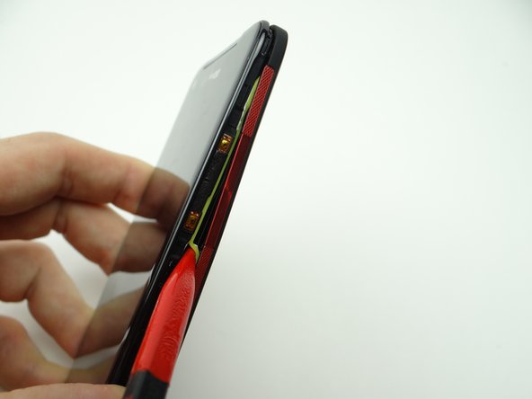
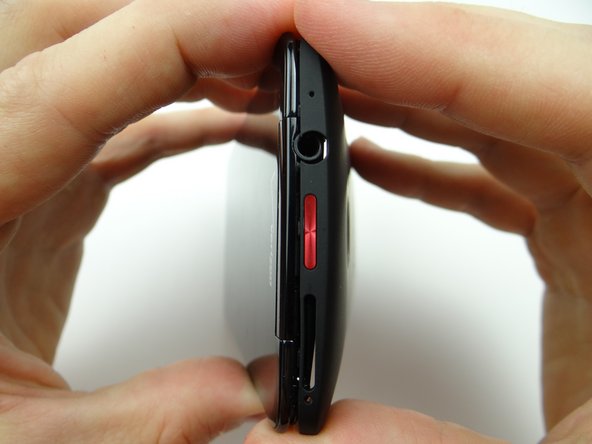
Picture 1: Sweep along the bottom edge from left to right releasing clips holding the battery cover down.
-
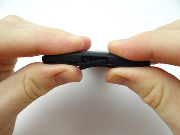
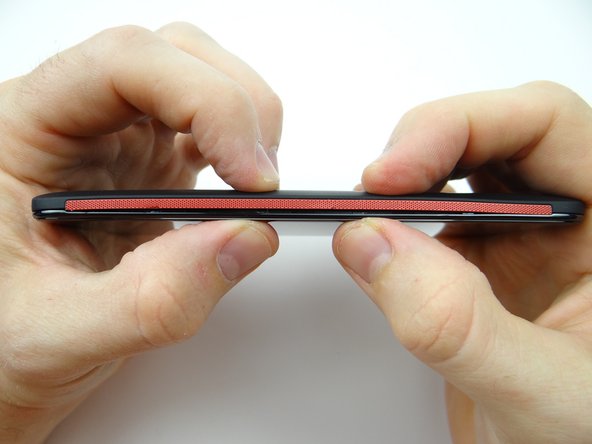
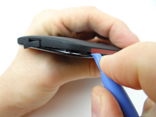
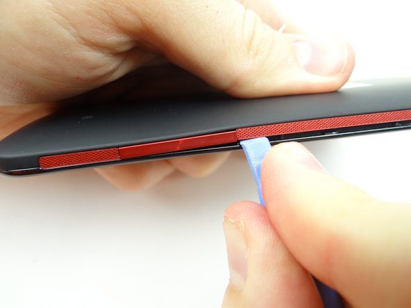
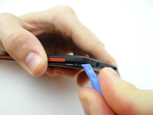
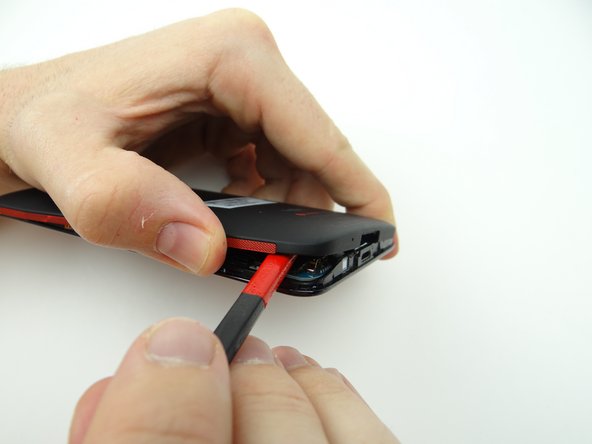
Picture 2: Slowly work your way around the corner gently prying up as you go.
-
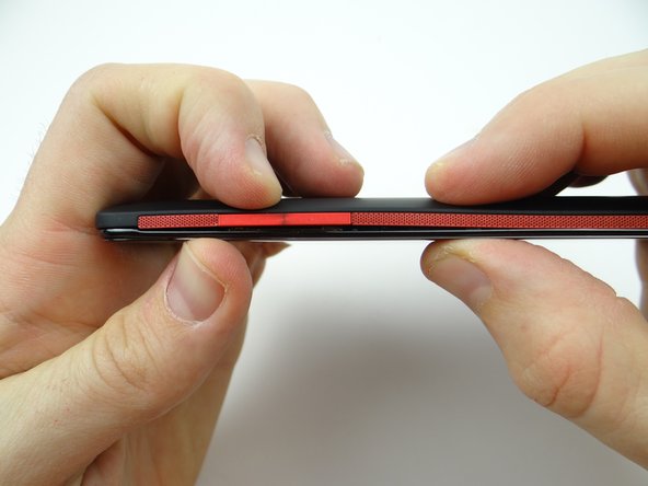
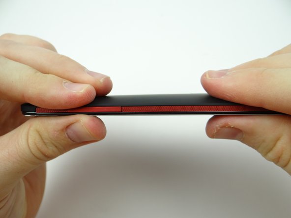
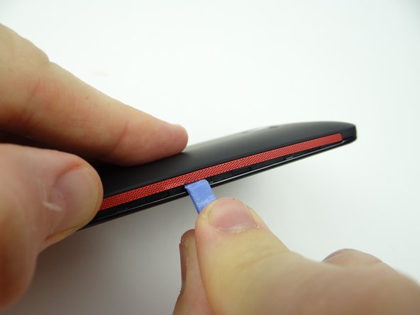
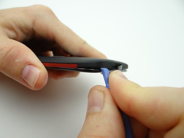
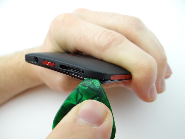
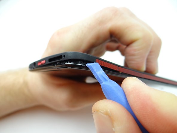
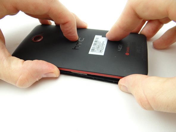
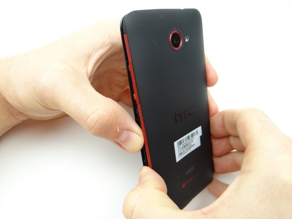
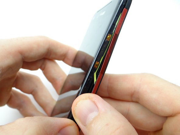
Picture 3: Work your way up the side (the side opposite the volume rocker), holding the battery cover up with your thumb.
-
-
-
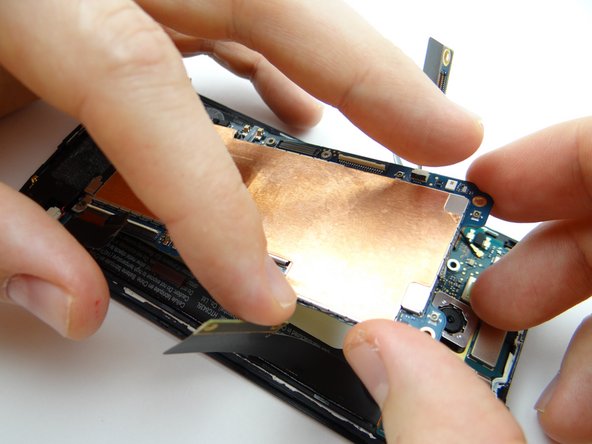
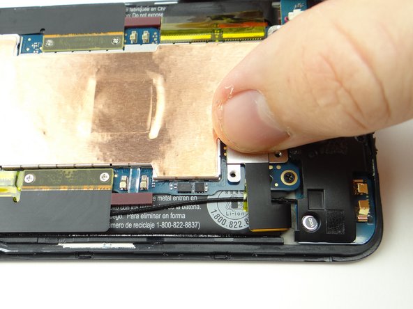
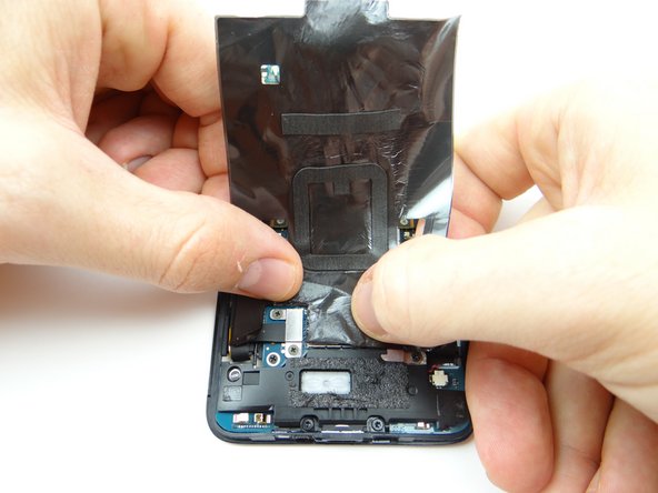
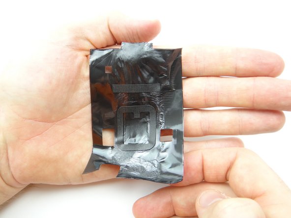
Pinch the black tape covering the logic board in the upper-left corner.
-
Gently peel it away from the phone.
-
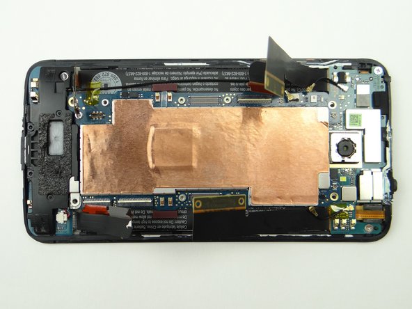
Place the black tape in ZONE I on top of the battery cover.
-
-
-
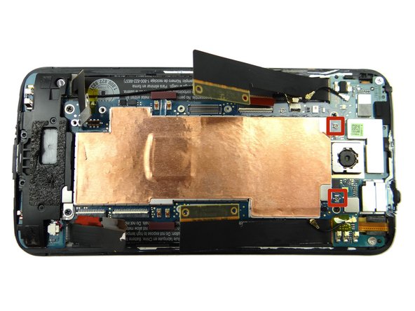
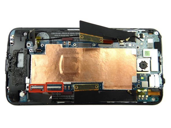
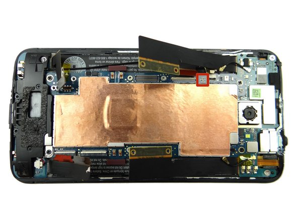
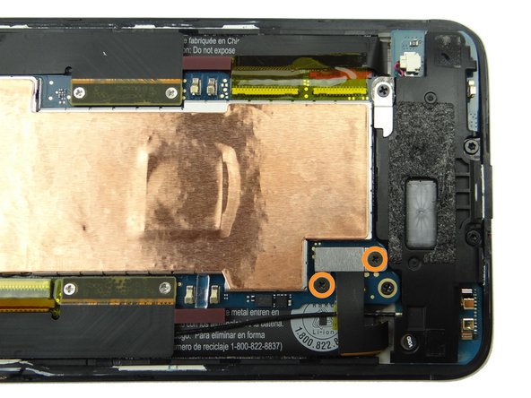
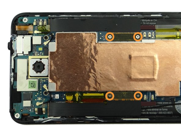
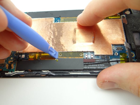
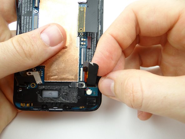
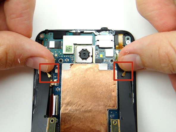
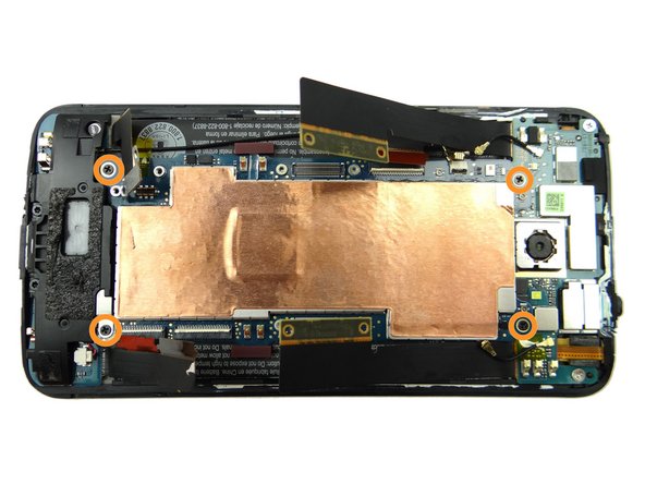
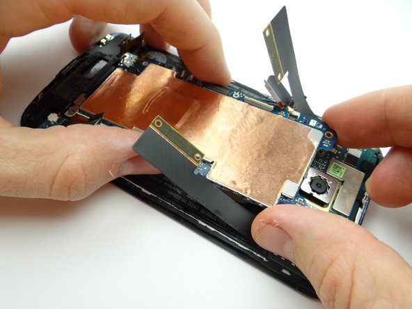
Picture 1: Remove four 1.6 mm Phillips #00 screws securing the two large daughter board flex cables. Place in SLOT 2.
-
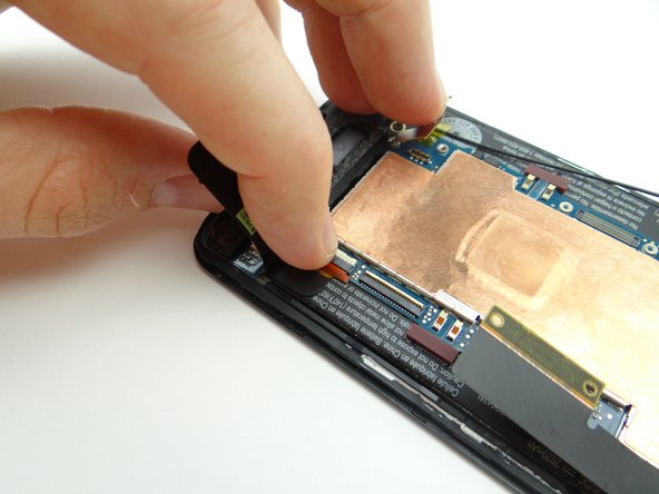
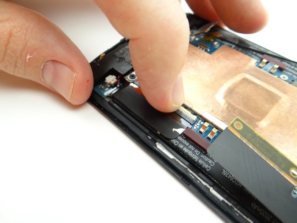
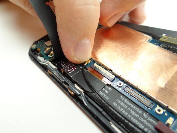
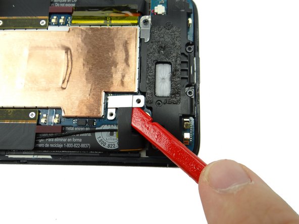
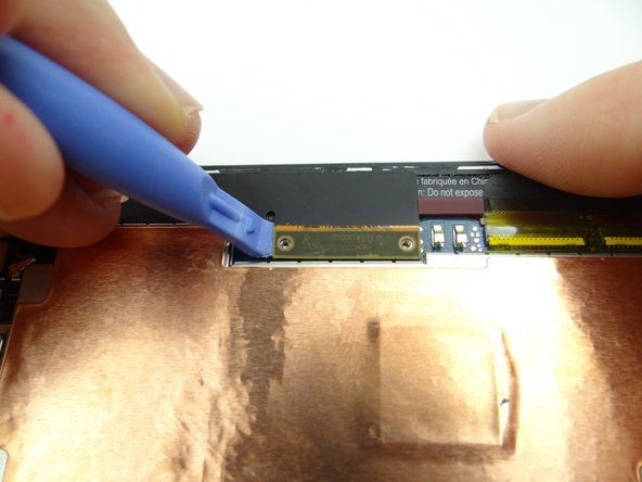
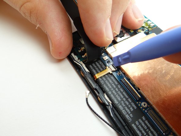
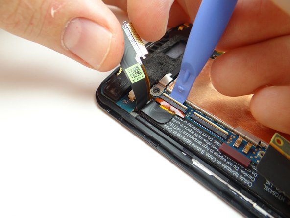
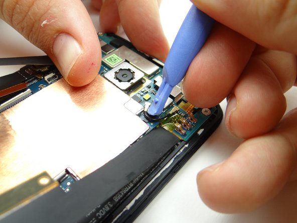
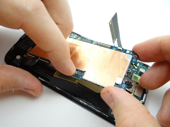
Pictures 2 & 3: Use the blue pry tool to disconnect the two large daughter board flex cables from the main logic board.
-
-
-
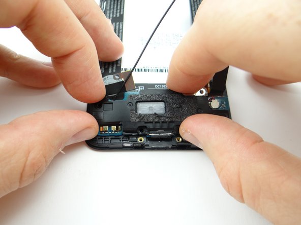
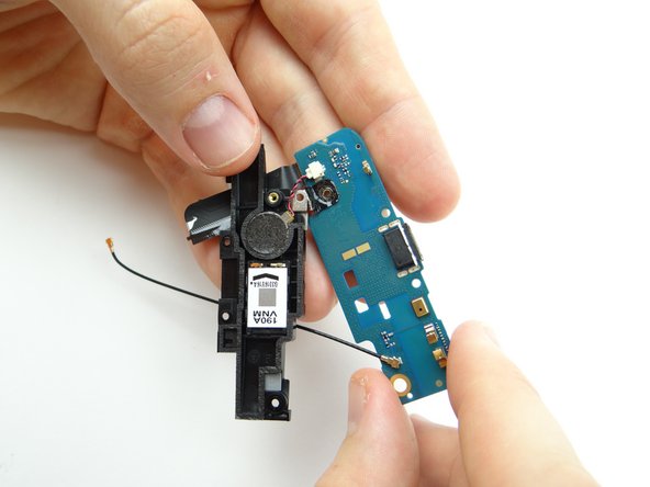
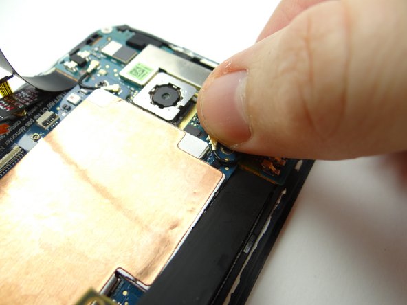
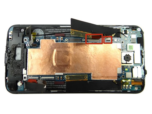
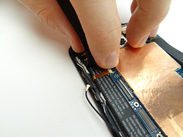
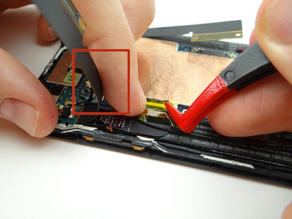
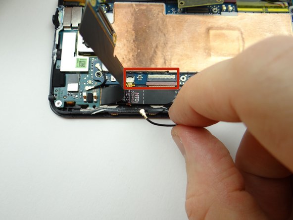
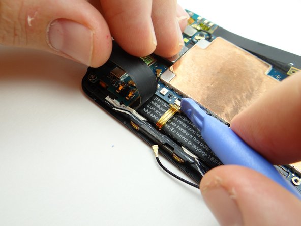
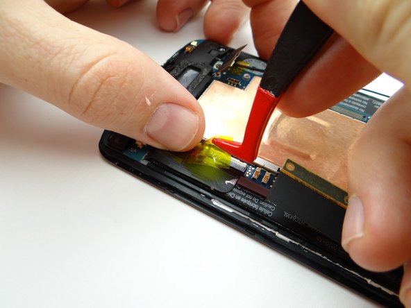
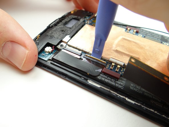
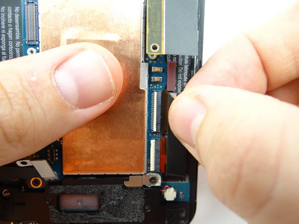
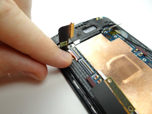
Hold the left daughter board flex cable up (red square in Picture 1) to expose cables:
-
Picture 1: Peel up Kapton tape covering ZIF connectors & antenna connector.
-
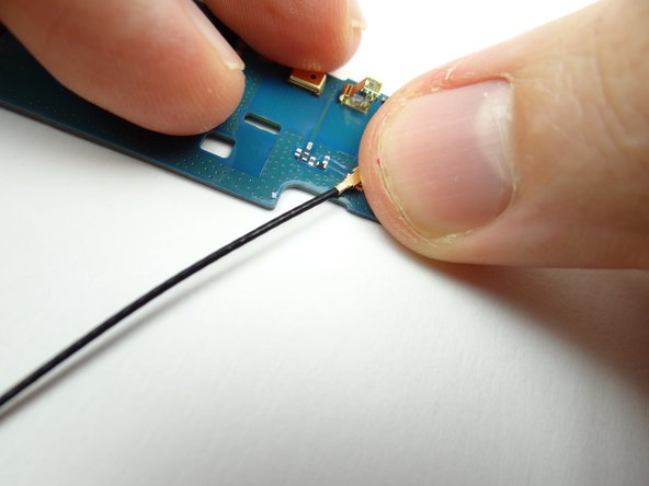
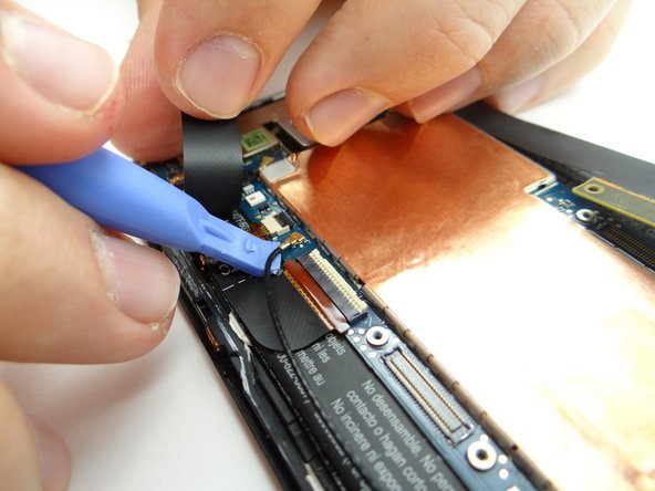
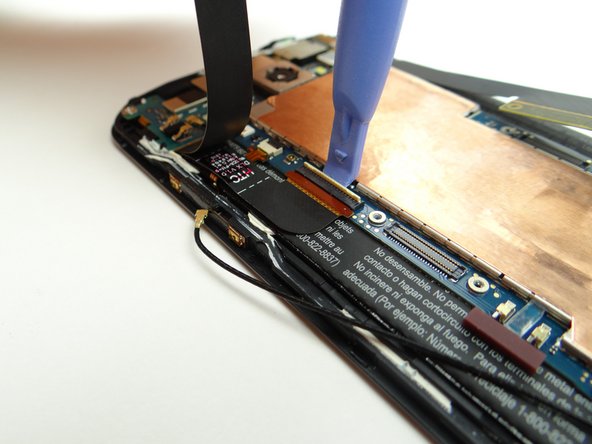
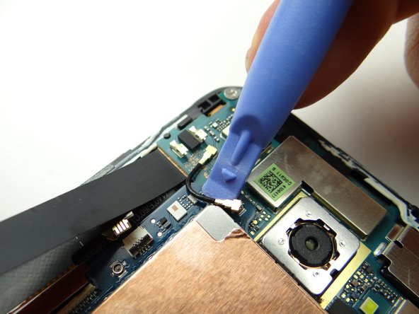
Picture 2: Disconnect antenna cable with the blue pry tool placed exactly where shown.
-
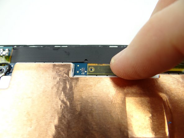
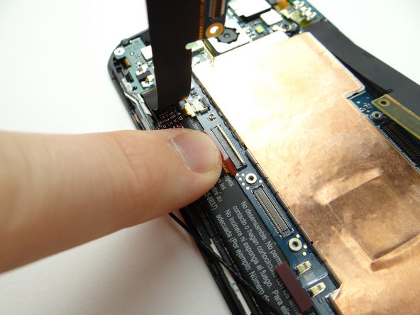
Picture 3: Move antenna cable out of the way to access the ZIF connectors on either side of the antenna connector.
-
-
-
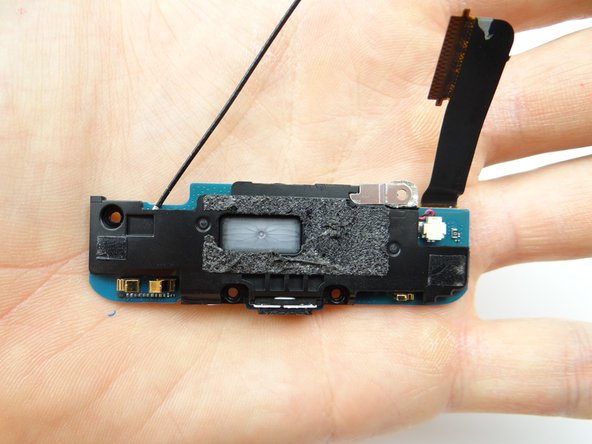
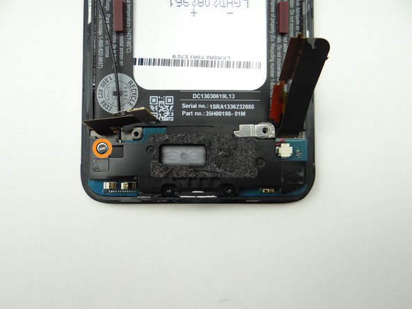
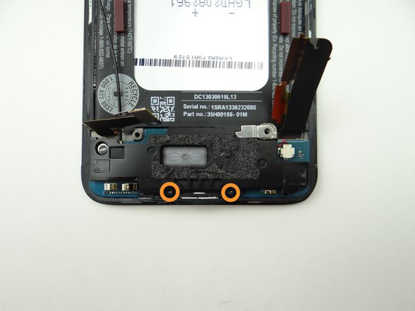
Picture 1: Remove 2.7 mm Phillips #00 'void sticker screw'. Place in SLOT 5.
-
Picture 2: Remove two 4.0 mm T5 Torx screws. Place in SLOT 6.
-
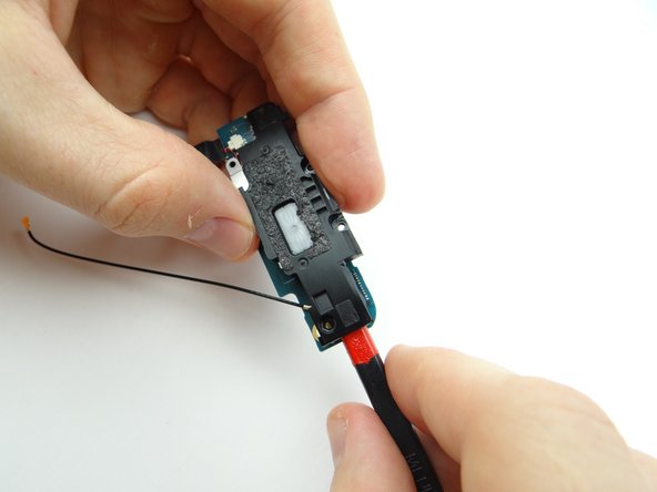
Picture 3: Pivot antenna cable from under the battery cover [to over it as shown].
-
-
-
Picture 1: Remove 2.1 mm #00 Phillips screw. Place in SLOT 7.
-
Picture 2: Wedge flat end of spudger as pictured.
-
Picture 3: Flip the bracket over.
-
-
-
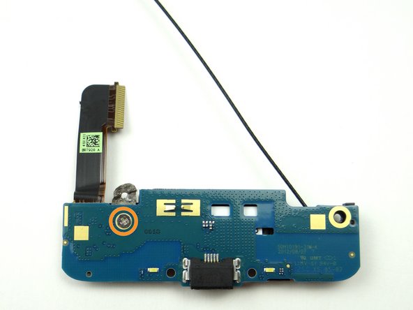
Picture 1: Seat wifi antenna cable on charging port assembly from ZONE IV.
-
Pictures 2 & 3: Fold vibrator bracket onto charging port.
-
-
-
Replace charging port assembly.
-
Tuck antenna cable under battery connector.
-
-
-
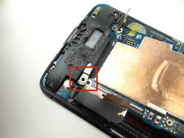
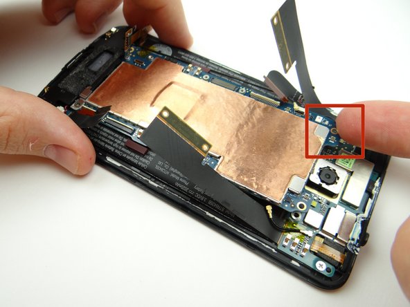
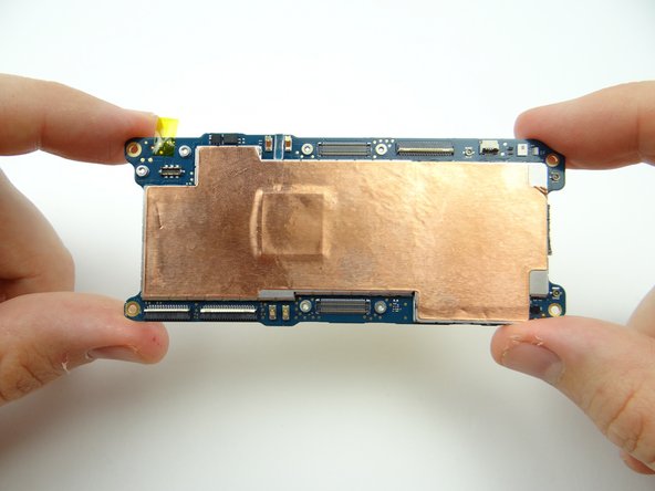
From ZONE II, replace logic board.
-
Make sure the opening on the logic board sits under the tab on the charging port (red square).
-
Brush cables out of the way as you continue seating the logic board.
-
-
-
Seat battery cable.
-
Replace two 1.5 mm Phillips #00 screws from SLOT 1.
-
-
-
From ZONE I, replace battery cover:
-
Pictures 1 & 2: Align tabs first.
-
Picture 3: Push top of battery cover into place.
-


![Picture 3: Pivot antenna cable from under the battery cover [to over it as shown].](https://d3t0tbmlie281e.cloudfront.net/igi/sandbox/YNDDLnN3i6yQHRyD.medium)