Parts
No parts specified.
-
-
Before disassembling the iPhone, thoroughly wash and dry your hands.
-
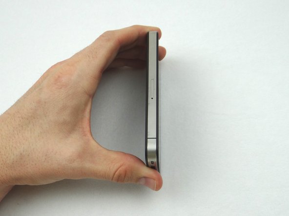
Make sure handset is powered off. Use a SIM card eject tool or a paperclip to eject the SIM card tray. This may require a significant amount of force.
-
Place the SIM card and SIM card tray in COMPARTMENT A.
-
-
-
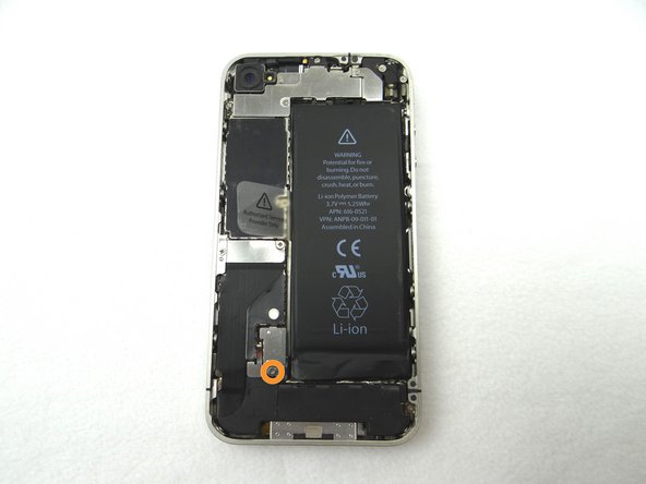
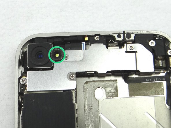
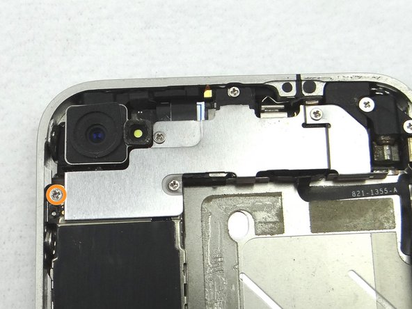
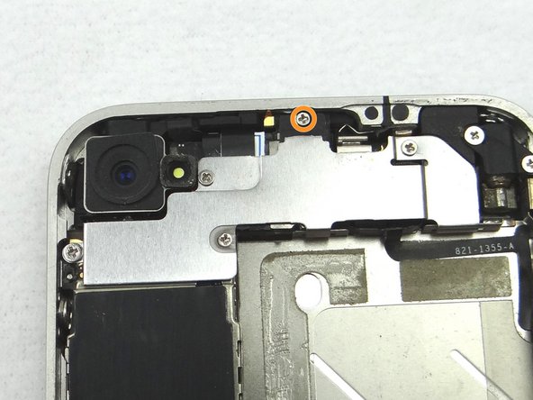
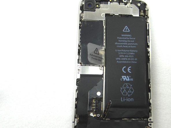
Picture 1: Remove the 2.5 mm Phillips screw and place in SLOT 2.
-
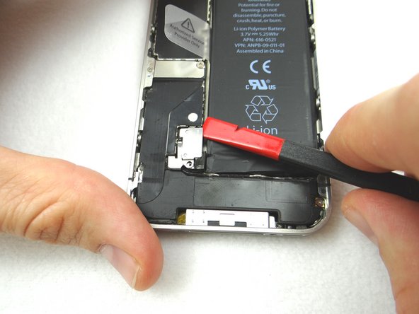
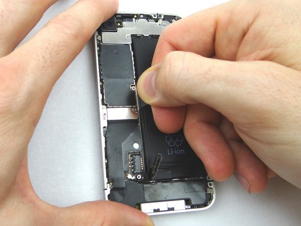
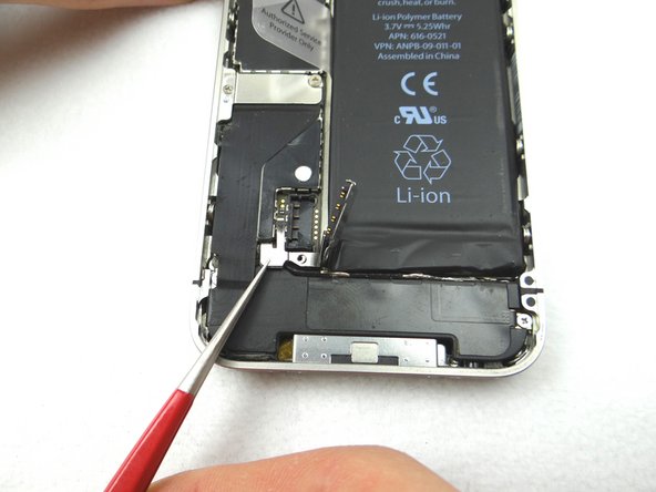
Picture 2: Place the flat end of the Black Spudger (tip is painted red for better illustration) at the top of the battery connector. Gently twist the spudger counter-clockwise to lift the connector from its socket.
-
Be very careful to only pry up on the battery connector and not the socket on the logic board. If you pry on the socket, you could break the socket off the logic board.
-
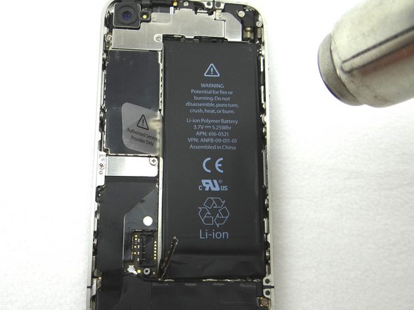
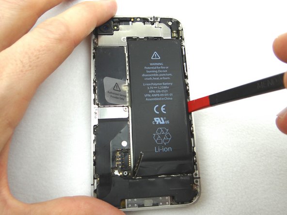
Picture 3: Use Fine Point Tweezers to remove the T-Shaped Antenna Shield. Place the Antenna Shield with the screw in SLOT 2.
-
-
-
Apply low-level heat (100* Celcius or less) to edges of battery for 60 seconds to loosen the adhesive securing the battery to the iPhone.
-
Wedge the flat end of the Black Spudger on the right edge of the battery. Gently pry up in three or four spots along the right edge to release the adhesive adhering it to the mid-frame.
-
Once loose, use the plastic pull tab to peel the battery free from the iPhone. Place the battery in ZONE II
-
-
-
Use a pair of tweezers to remove the outer plastic ring (if present) located on top of the rear camera's flash. Place in COMPARTMENT B.
-
-
-
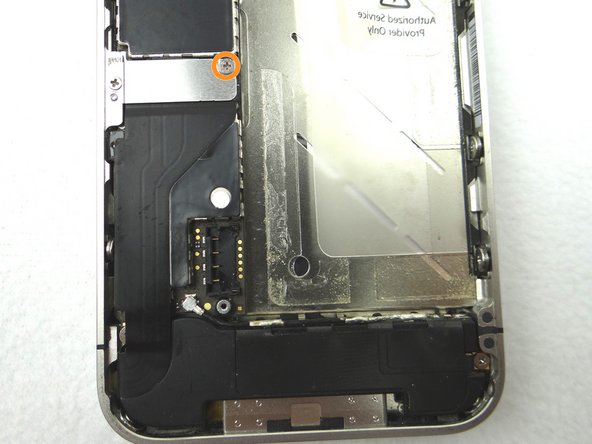
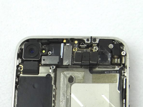
Picture 1: Remove 4.8 mm Phillips screw and place in SLOT 6.
-
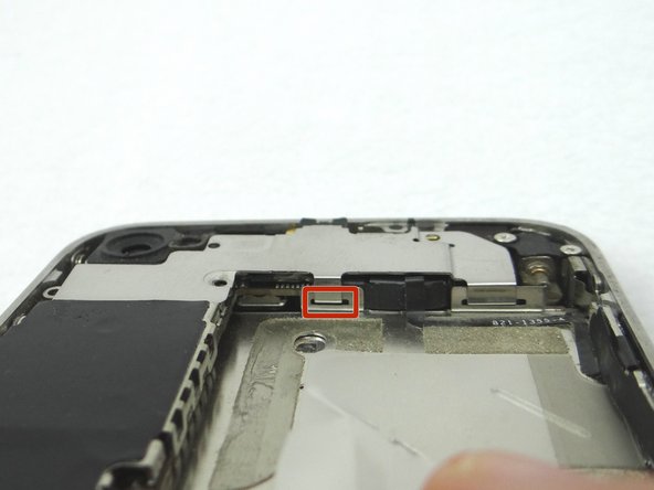
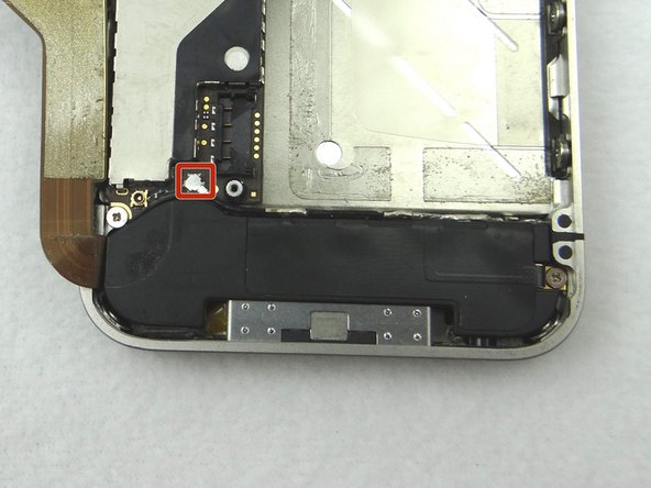
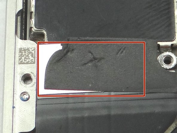
Picture 2: Picture of the cable shield clipped to the mid-frame.
-
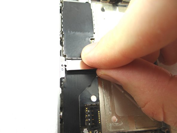
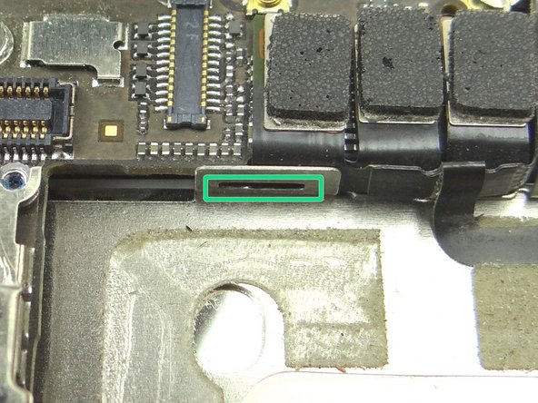
Next, slowly pull Cable Shield towards bottom of iPhone until the tabs at the bottom of the shield (see red squares) are free.
-
Place Cable Shield in COMPARTMENT B (with the plastic ring from the camera flash, if present)
-
-
-
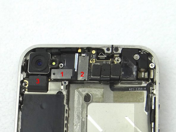
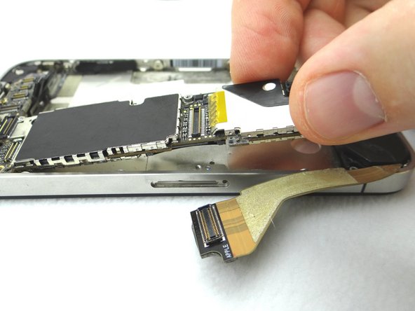
Picture 1: Disconnect three ribbon cables in order.
-
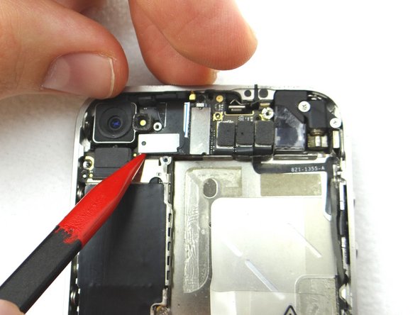
Picture 2: Use the flat end of the black spudger to gently pry three cables free from their sockets on the logic board.
-
Be careful not to break any components off the surrounding area on the logic board as you pry upwards.
-
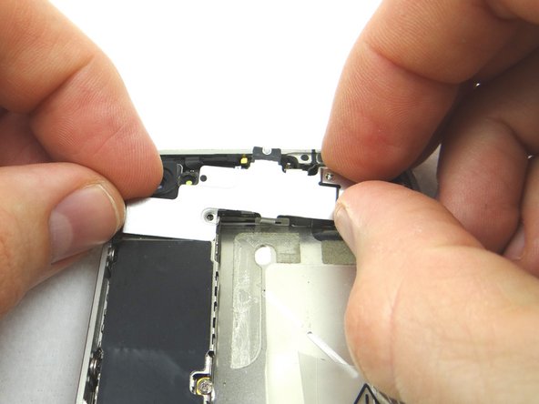
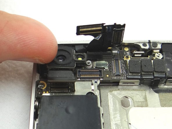
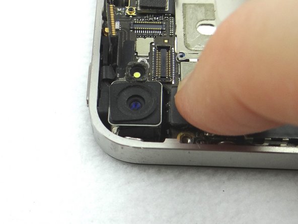
Picture 3: Remove the Rear Camera with your fingers. Place in COMPARTMENT C.
-
-
-
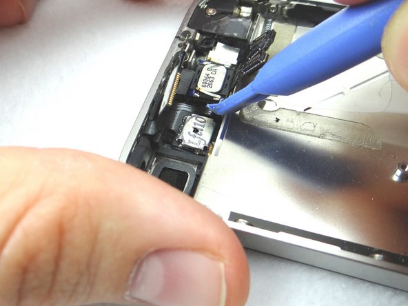
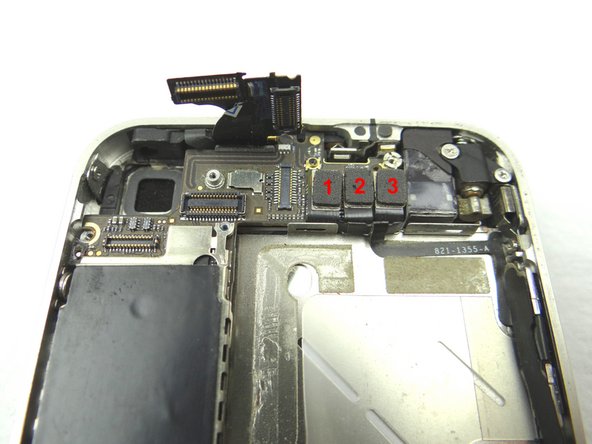
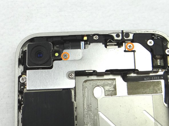
Picture 1: Disconnect three cables in order.
-
Picture 1: Release cables '1' , '2' , and '3'. Use the Black Spudger to gently lift the connectors up and out of the sockets.
-
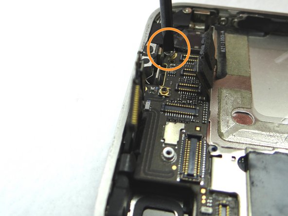
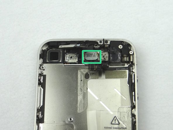
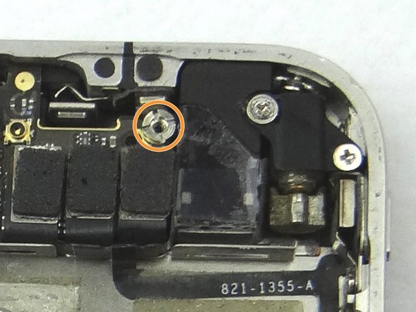
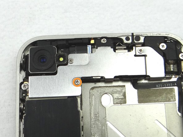
Picture 2: Remove the 4.8 mm standoff with a 2.4 mm flathead screwdriver and place in SLOT 7.
-
Picture 3: Remove the 1.2 mm Phillips screw and place in SLOT 8.
-
-
-
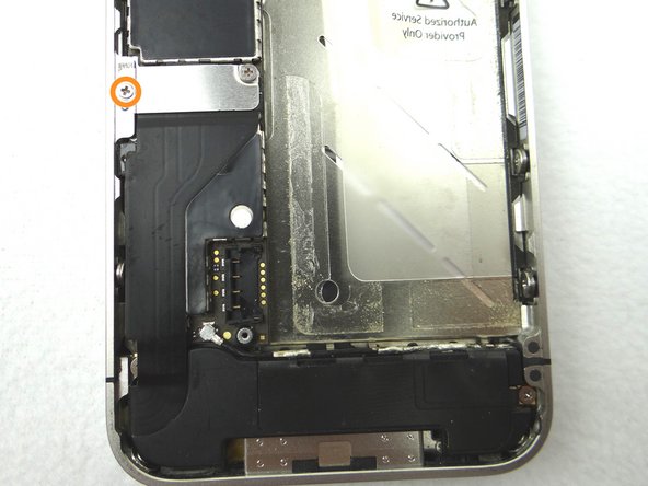
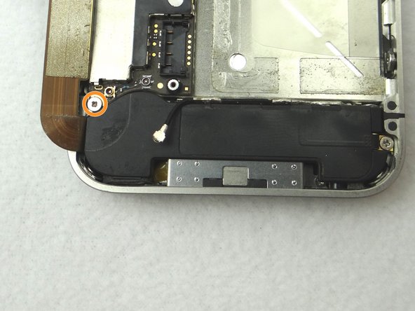
Picture 1: Remove 1.6 mm Phillips screw and place in SLOT 9.
-
Picture 2: Remove the charging port assembly shield and place with screw in SLOT 9.
-
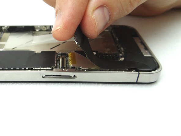
Picture 3: Place flat end of spudger under lower-right corner of the charging port assembly cable. Gently twist your hand clockwise releasing the cable from its socket on the logic board.
-
-
-
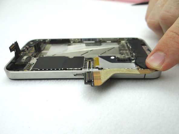
Picture 1: The charging port assembly cable is adhered to the logic board – gently peel it free from the logic board, working top to bottom until cable is free of logic board. Be cautious as this cable is very fragile.
-
Picture 2: Fold the cable to the left.
-
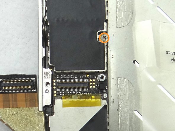
Picture 3: Remove the 2.4 mm Phillips screw and place it SLOT 10.
-
There may be a white sticker (liquid damage indicator) on top of the Phillips screw. If so, either remove it with tweezers or push through it with your screwdriver.
-
-
-
Picture 1: Carefully lift the logic board just high enough to pinch it with your left thumb and index finger.
-
Once you have a good grip on the logic board, use your right hand to brush away cables near the top while pulling the logic board towards you until it is free from the mid-frame. Place in ZONE III.
-
Picture 2: There should be a rubber washer at the top of the logic board. It falls off easily and may get stuck in the mid-frame while you remove the logic board. Make sure to place it on the top left edge of the logic board.
-
-
-
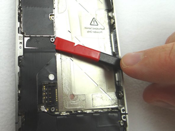
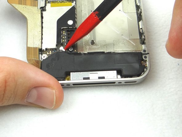
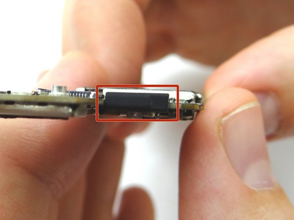
Picture 1: Wedge the Blue Pry Tool beneath the speaker (held by adhesive). Gently pry upwards. Place into COMPARTMENT D.
-
-
-
Picture 1: Ensure the rubber washer is in place on the logic board before the logic board is put back into place.
-
Picture 2: Grab the logic board from ZONE III and carefully position the top edge into the mid-frame. Make sure the top edge is below the protruding tab on the mid-frame.
-
Push the logic board down into its position on the mid-frame.
-
Make sure no cables get trapped under the logic board while re-installing it.
-
-
-
Picture 1: Replace Rear Camera from COMPARTMENT C (or replacement part). Push connector into socket on logic board.
-
Also in Picture 1: Reconnect the digitizer and LCD cables sitting upright.
-
Picture 2: This is what you should see after connecting the camera, digitizer and LCD cables.
-
-
-
Picture 1: Place the battery from ZONE II (or replacement part) in the mid-frame.
-
Picture 2: With Fine Point Tweezers, place the T-Shaped Antenna Shield from SLOT 2 between the battery connector and its socket.
-
Make sure the screw slot on the battery connector lines up with the screw slot on the Antenna Shield, and that they both line up with the screw slot on the battery socket. If needed use tweezers to adjust its position.
-
Picture 3: Use the 2.5 mm Phillips screw from SLOT 2 to secure the bottom of the battery connector.
-
-
-
Picture 1: Replace battery cover from ZONE I (or replacement part). Gently slide battery cover downward until it locks into place.
-
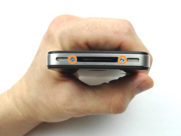
Picture 2: Place the handset in your non-dominant hand, then replace two Pentalobe screws near charging port with special 5-point Pentalobe screwdriver. The screws are in SLOT 1.
-
Picture 3: Replace the SIM card and SIM card tray from Sandbox COMPARTMENT A.
-