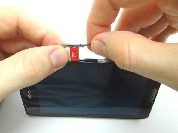
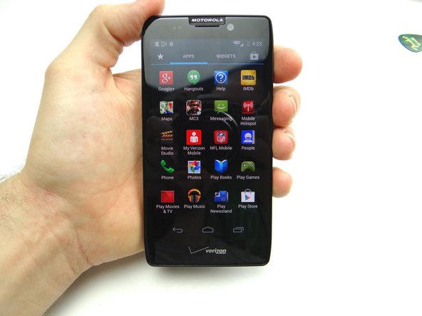
1. Before disassembly, thoroughly wash and dry your hands.  Power down the device. Find the opening in the SIM card tray roughly an inch above the charging port.  Gently push a small paper clip into the opening to 'pop up' the SIM card tray. Remove the tray, SIM card and SD card.  Place all three in COMPARTMENT A.
    • Before disassembly, thoroughly wash and dry your hands. Power down the device.

    • Find the opening in the SIM card tray roughly an inch above the charging port. Gently push a small paper clip into the opening to 'pop up' the SIM card tray.

    • Remove the tray, SIM card and SD card. Place all three in COMPARTMENT A.

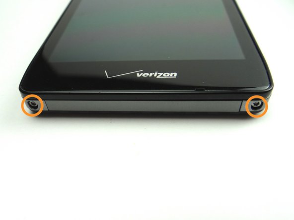
  2. Picture 1: Remove two 4.8 mm T5 Torx screws.  Place in SLOT 1. Picture 2: With your thumbs placed on the screen as pictured, shimmy the screen up from the bottom of the phone. Picture 3: The screen comes up just a couple millimeters as shown.
    • Picture 1: Remove two 4.8 mm T5 Torx screws. Place in SLOT 1.

    • Picture 2: With your thumbs placed on the screen as pictured, shimmy the screen up from the bottom of the phone.

    • Picture 3: The screen comes up just a couple millimeters as shown.

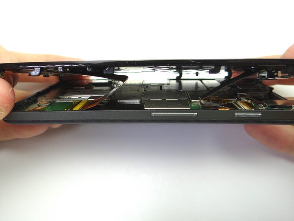
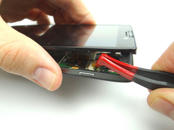
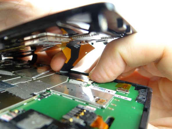
  3. Lift the front panel an inch above the rear panel. The component cable connector is next to the power button: peel up the yellow Kapton tape covering the connector.
    • Lift the front panel an inch above the rear panel.

    • The component cable connector is next to the power button: peel up the yellow Kapton tape covering the connector.

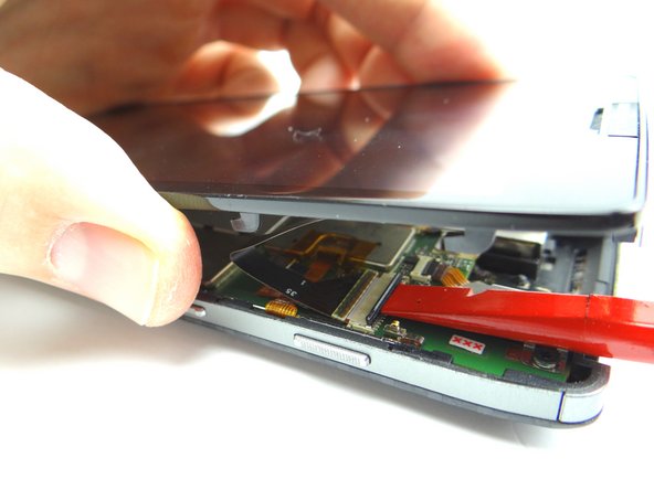
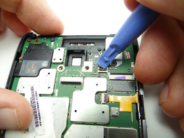
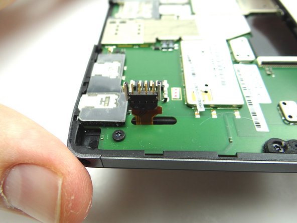
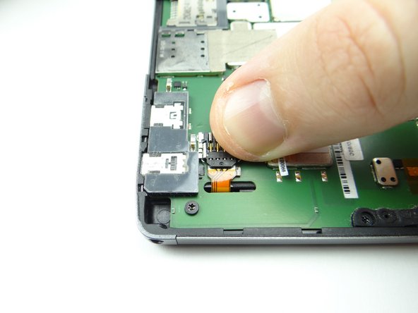
  4. Picture 1: Use flat end of spudger to push the black ZIF connector bar into open position as shown. Picture 2: Gently guide the component cable out of the ZIF connector.
    • Picture 1: Use flat end of spudger to push the black ZIF connector bar into open position as shown.

    • Picture 2: Gently guide the component cable out of the ZIF connector.

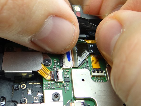
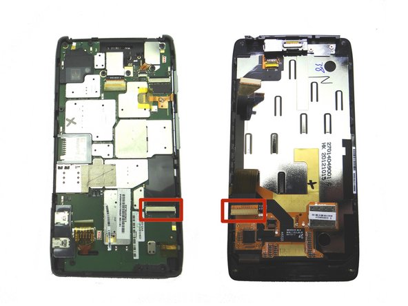
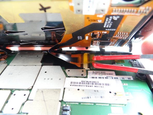
  5. The display cable connector is two inches down from the component connector: Picture 1: Peel up yellow Kapton tape with plastic tweezers.  Adhere the tape to the wall of COMPARTMENT E.  (You'll need a piece of Kapton tape for reassembly to help hold the display cable in place.) Picture 2: Use flat end of spudger to push the black ZIF connector open.
    • The display cable connector is two inches down from the component connector:

    • Picture 1: Peel up yellow Kapton tape with plastic tweezers. Adhere the tape to the wall of COMPARTMENT E. (You'll need a piece of Kapton tape for reassembly to help hold the display cable in place.)

    • Picture 2: Use flat end of spudger to push the black ZIF connector open.

    • Picture 3: Gently guide the display cable out of the ZIF connector.

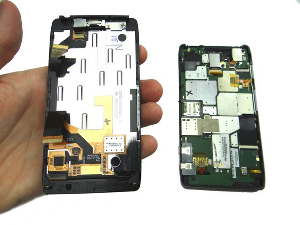
  6. Separate the front and rear panels and place them in ZONES I & II.
    • Separate the front and rear panels and place them in ZONES I & II.

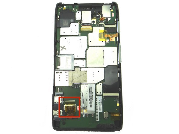
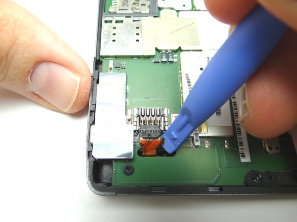
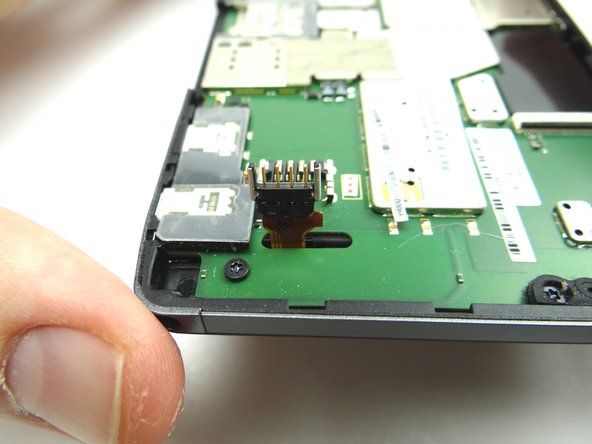
  7. Remove Kapton tape covering battery connector. Lift the battery connector into the upright position. This should take very little force.
    • Remove Kapton tape covering battery connector.

    • Lift the battery connector into the upright position.

    • This should take very little force.

  8. Picture 1: Use blue pry tool to open headphone jack ZIF connector. Picture 2: Remove two 3.6 mm T5 Torx screws.  Place in SLOT 2. Picture 3: The headphone jack cable is attached to the headphone jack cover.  Lift the cover while guiding the cable out of the ZIF connector.
    • Picture 1: Use blue pry tool to open headphone jack ZIF connector.

    • Picture 2: Remove two 3.6 mm T5 Torx screws. Place in SLOT 2.

    • Picture 3: The headphone jack cable is attached to the headphone jack cover. Lift the cover while guiding the cable out of the ZIF connector.

  9. Place cover / cable assembly in COMPARTMENT D.
    • Place cover / cable assembly in COMPARTMENT D.

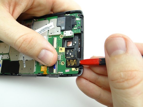
  10. Use the pointed tip of the spudger to pry the headphone jack free. Place headphone jack in COMPARTMENT D.
    • Use the pointed tip of the spudger to pry the headphone jack free.

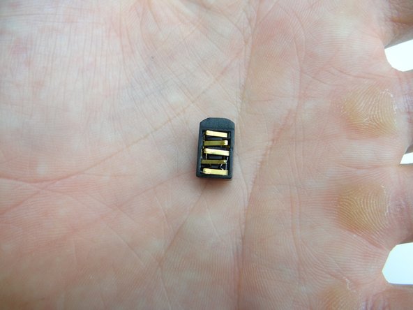
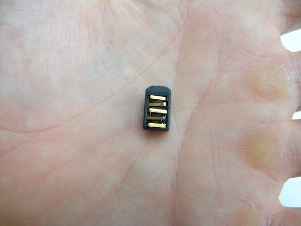
    • Place headphone jack in COMPARTMENT D.

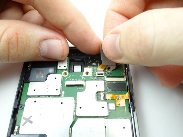
  11. From COMPARTMENT D, retrieve headset jack.  Use your fingers to place it as shown. From COMPARTMENT D, retrieve headset jack.  Use your fingers to place it as shown.
    • From COMPARTMENT D, retrieve headset jack. Use your fingers to place it as shown.

  12. From COMPARTMENT D, replace headphone jack cover: guide cable into ZIF connector while seating cover. From COMPARTMENT D, replace headphone jack cover: guide cable into ZIF connector while seating cover.
    • From COMPARTMENT D, replace headphone jack cover: guide cable into ZIF connector while seating cover.

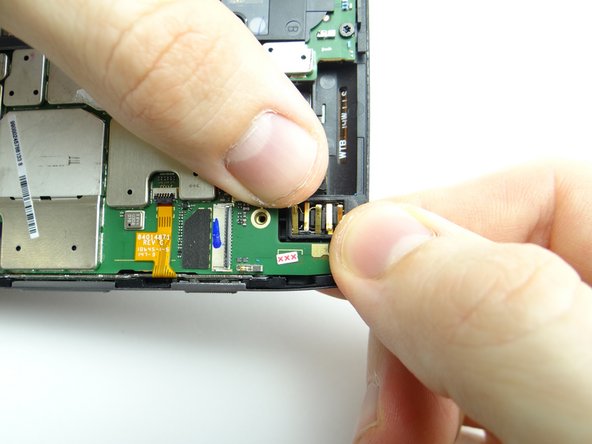
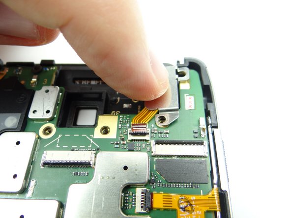
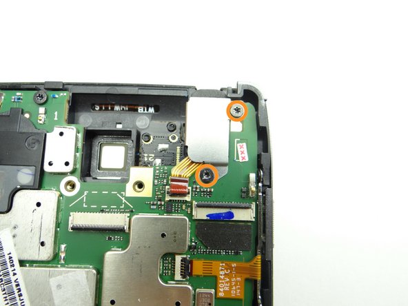
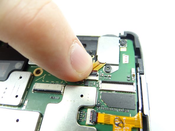
  13. Pictures 1 & 2: Hold down headphone jack cover while replacing two 3.6 mm T5 Torx screws from SLOT 2. Picture 3: Close ZIF connector. Picture 3: Close ZIF connector.
    • Pictures 1 & 2: Hold down headphone jack cover while replacing two 3.6 mm T5 Torx screws from SLOT 2.

    • Picture 3: Close ZIF connector.

  14. Connect component cable: Guide component cable into open ZIF connector. Hold component cable in place with one hand, while closing ZIF connector with your thumb on opposite hand.
    • Connect component cable:

    • Guide component cable into open ZIF connector. Hold component cable in place with one hand, while closing ZIF connector with your thumb on opposite hand.

  15. Picture 1: Connect display cable: Picture 2: Guide display cable into open ZIF connector. Hold display cable in place with one hand, while closing ZIF connector with your thumb on opposite hand. Picture 3: Cover the display cable connector with Kapton tape from COMPARTMENT E.
    • Picture 1: Connect display cable:

    • Picture 2: Guide display cable into open ZIF connector. Hold display cable in place with one hand, while closing ZIF connector with your thumb on opposite hand.

    • Picture 3: Cover the display cable connector with Kapton tape from COMPARTMENT E.

    • The display cable has a tendency to come loose when closing the front panel on the rear panel. It's important to replace the yellow Kapton tape to ensure the cable is held in place.

  16. Seat the front panel on the rear panel up a couple millimeters from the bottom of the rear panel.  Slide the front panel down into place. Picture 2: Replace two 4.8 mm T5 Torx screws from SLOT 1.
    • Seat the front panel on the rear panel up a couple millimeters from the bottom of the rear panel. Slide the front panel down into place.

    • Picture 2: Replace two 4.8 mm T5 Torx screws from SLOT 1.

  17. From COMPARTMENT A, replace tray, SIM card and SD card. Power up the device and test the replacement component or components.
    • From COMPARTMENT A, replace tray, SIM card and SD card.

    • Power up the device and test the replacement component or components.

Finish Line
James Linder

Member since: 01/24/2013

71,591 Reputation

217 Guides authored

0 Comments

Add Comment

View Statistics:

Past 24 Hours: 0

Past 7 Days: 1

Past 30 Days: 1

All Time: 30

CELL PHONE SANDBOX