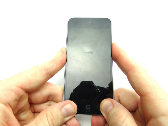
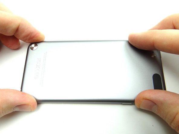
1. Picture 1: There is adhesive across the  bottom on either side of the home button. Picture 2: There are 3 clips on each side of the screen. Picture 3: There are 2 clips at the top of the screen.
    • Picture 1: There is adhesive across the bottom on either side of the home button.

    • Picture 2: There are 3 clips on each side of the screen.

    • Picture 3: There are 2 clips at the top of the screen.

    • You'll be releasing the clips and adhesive in the next steps to open the iPod:

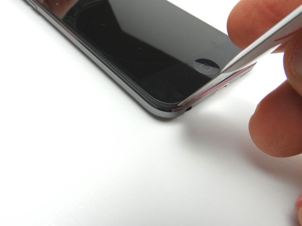
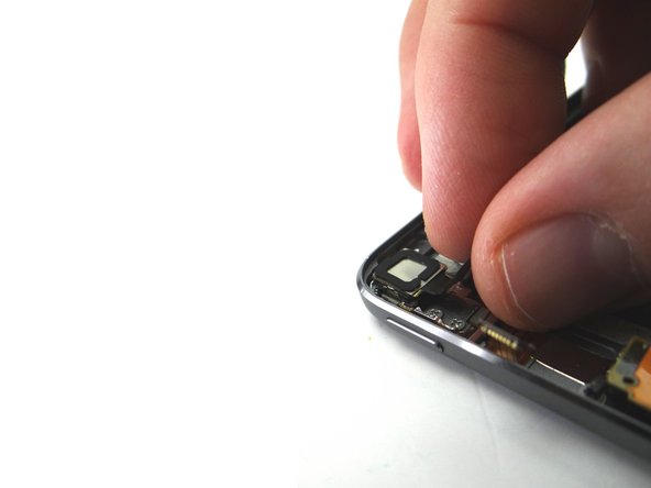
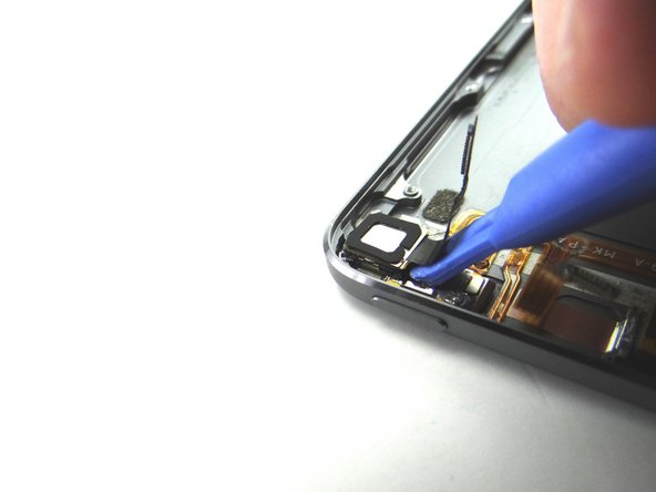
  2. Picture 1: Place the suction cup on the screen just above the home button.  Apply low-level heat (100 degrees Celsius) to the bottom edge of the iPod for about a minute. Pictures 2 & 3: Use the suction cup to pull the front panel up just enough to wedge the blue pry tool in between the front panel and rear case. Remove suction cup once you've wedged the blue pry tool.
    • Picture 1: Place the suction cup on the screen just above the home button. Apply low-level heat (100 degrees Celsius) to the bottom edge of the iPod for about a minute.

    • Pictures 2 & 3: Use the suction cup to pull the front panel up just enough to wedge the blue pry tool in between the front panel and rear case.

    • Remove suction cup once you've wedged the blue pry tool.

    • If you're unable to create suction (e.g. the screen is badly cracked), we provide a back-up method in the next step.

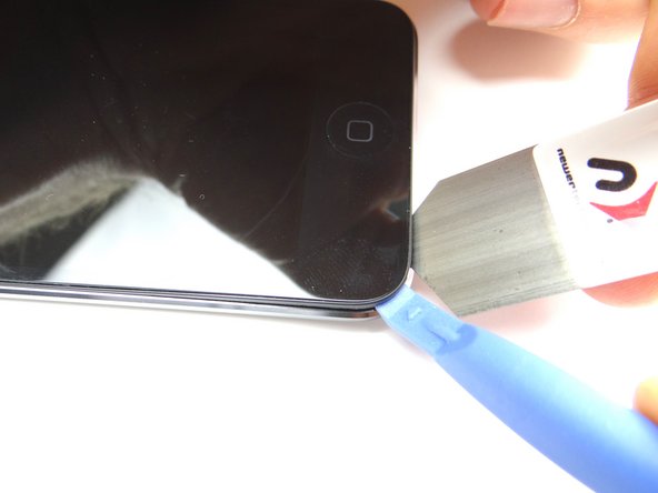
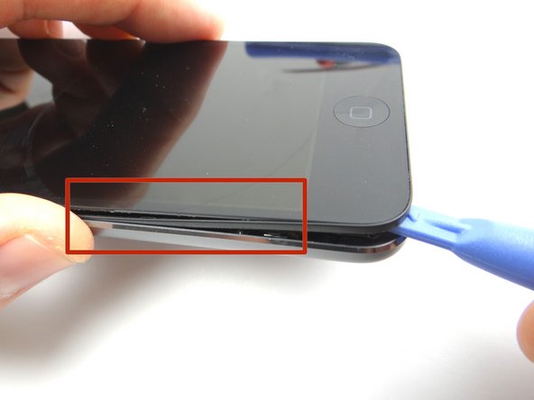
  3. Skip this step if the suction cup method worked. Picture 1: Wedge iSesamo underneath the black bezel around the screen. Picture 2: Pry up just enough to wedge blue pry tool and remove the iSesamo.
    • Skip this step if the suction cup method worked.

    • Picture 1: Wedge iSesamo underneath the black bezel around the screen.

    • Picture 2: Pry up just enough to wedge blue pry tool and remove the iSesamo.

    • Picture 3: Continue prying up under the bezel with the blue pry tool.

    • If you're replacing the screen and it comes with the bezel pre-installed, pry between the screen and bezel to minimize the likelihood of damaging the rear case.

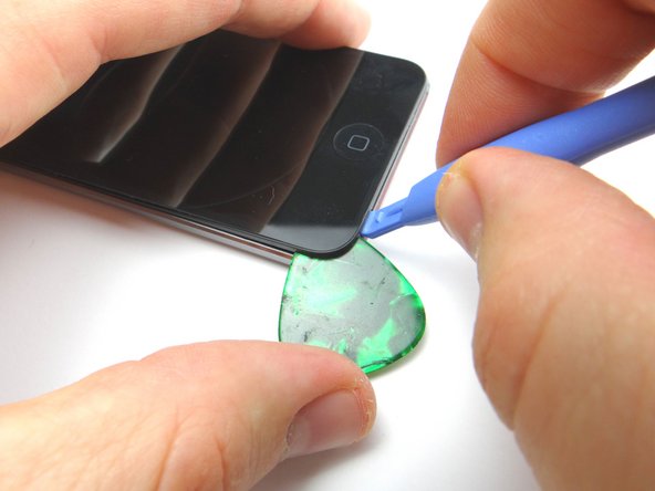
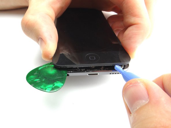
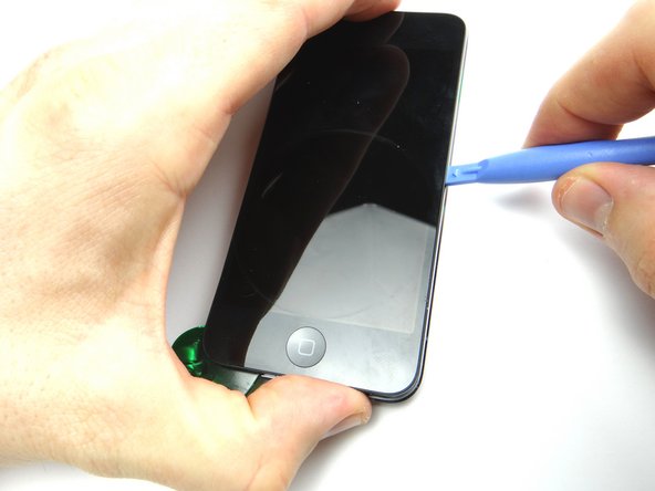
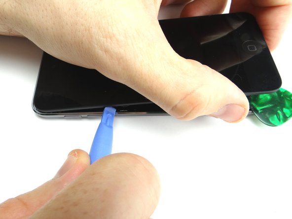
  4. Wedge a guitar pick in the lower-left corner. Using the blue pry tool, work your way around the perimeter of the iPod prying up as you go. Using the blue pry tool, work your way around the perimeter of the iPod prying up as you go.
    • Wedge a guitar pick in the lower-left corner.

    • Using the blue pry tool, work your way around the perimeter of the iPod prying up as you go.

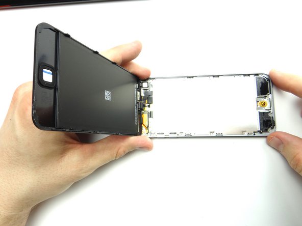
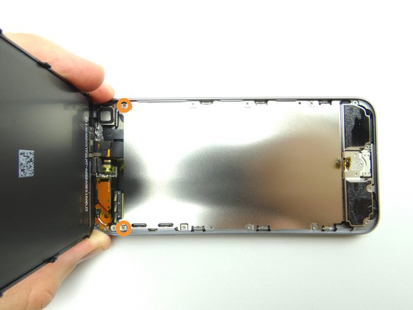
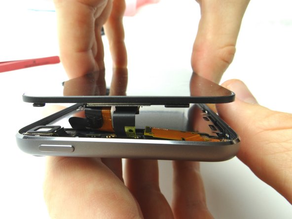
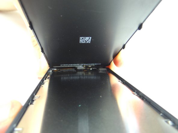
  5. After releasing the clips holding the front panel in place, use your fingers to open the iPod. Don't open iPod past a 90° angle.  Continue holding it open at a 90° angle for the next several steps.
    • After releasing the clips holding the front panel in place, use your fingers to open the iPod.

    • Don't open iPod past a 90° angle. Continue holding it open at a 90° angle for the next several steps.

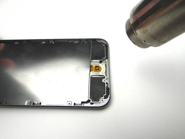
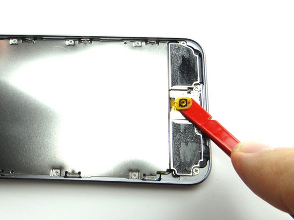
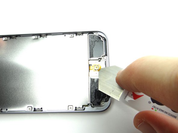
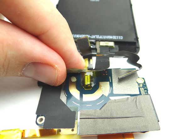
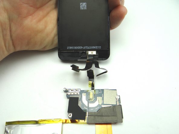
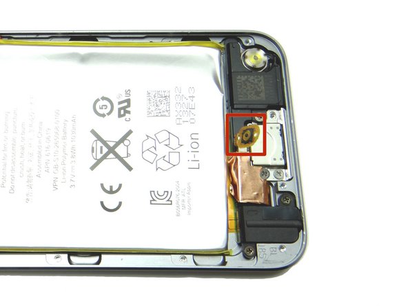
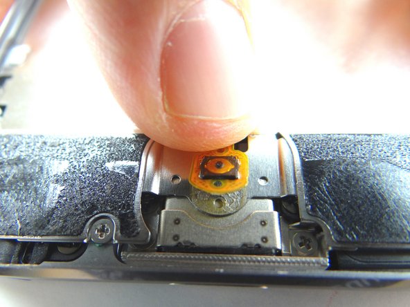
  6. Picture 1: Apply low-level heat (100° Celsius) to the home button contact for 30 seconds. Picture 2: Use the spudger to peel up the home button contact. Picture 3: If you can't wedge the spudger under the home button contact, use your fingernail or iSesamo to get it started.
    • Picture 1: Apply low-level heat (100° Celsius) to the home button contact for 30 seconds.

    • Picture 2: Use the spudger to peel up the home button contact.

    • Picture 3: If you can't wedge the spudger under the home button contact, use your fingernail or iSesamo to get it started.

    • Don't try to remove the home button contact - it's still connected to the logic board.

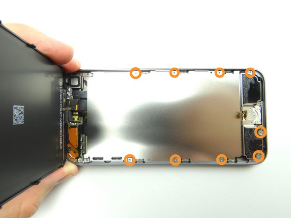
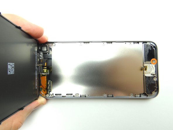
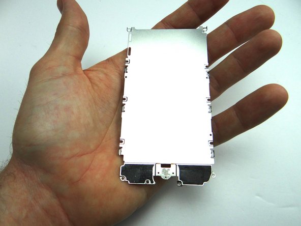
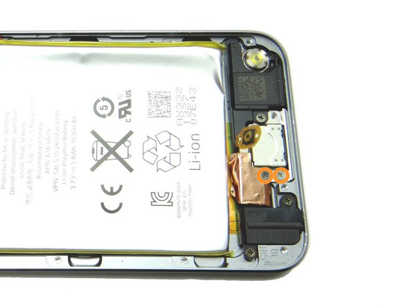
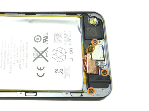
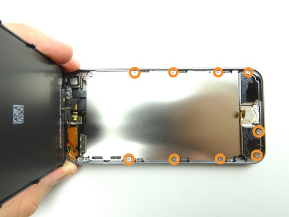
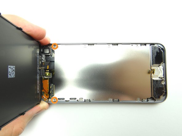
  7. Picture 1: Remove two 1.2 mm #00 Phillips screws.  Place in SLOT 1. Picture 2: Remove nine 1.6 mm #00 Phillips screws.  Place in SLOT 2. Picture 3: Remove one 2.3 mm #00 Phillips screw.  Place in SLOT 3.
    • Picture 1: Remove two 1.2 mm #00 Phillips screws. Place in SLOT 1.

    • Picture 2: Remove nine 1.6 mm #00 Phillips screws. Place in SLOT 2.

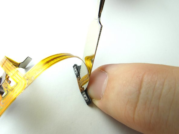
    • Picture 3: Remove one 2.3 mm #00 Phillips screw. Place in SLOT 3.

  8. Lift metal plate from bottom taking care to feed home button through its slot. Place metal plate in ZONE I. Place metal plate in ZONE I.
    • Lift metal plate from bottom taking care to feed home button through its slot.

    • Place metal plate in ZONE I.

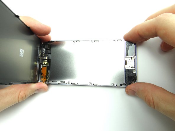
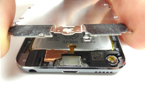
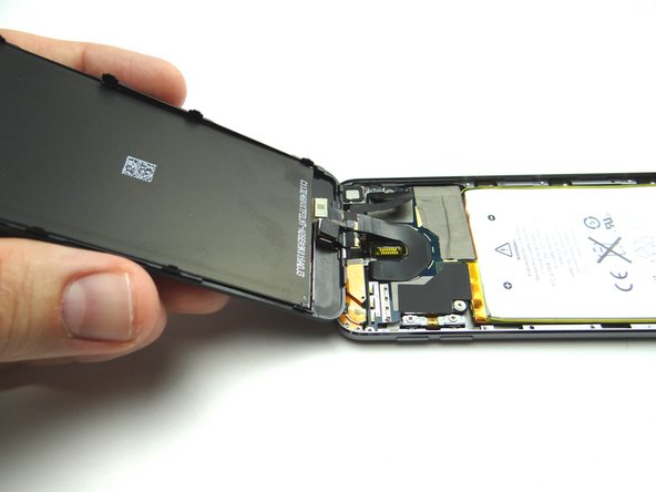
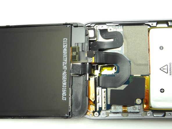
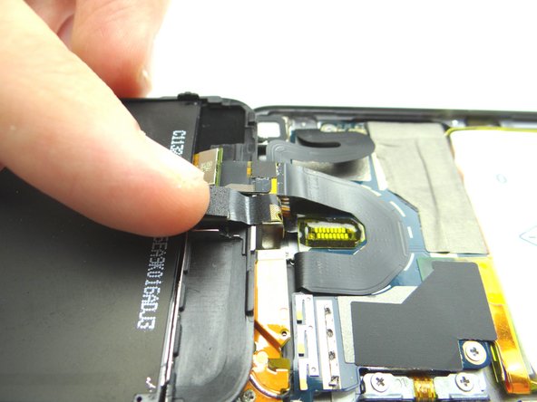
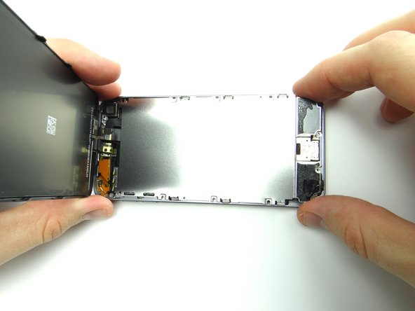
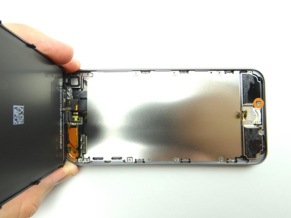
  9. Picture 1: Once plate has been removed, you're able to fold back the front panel. Picture 2: Make sure the front panel rests on top of the rear case.
    • Picture 1: Once plate has been removed, you're able to fold back the front panel.

    • Picture 2: Make sure the front panel rests on top of the rear case.

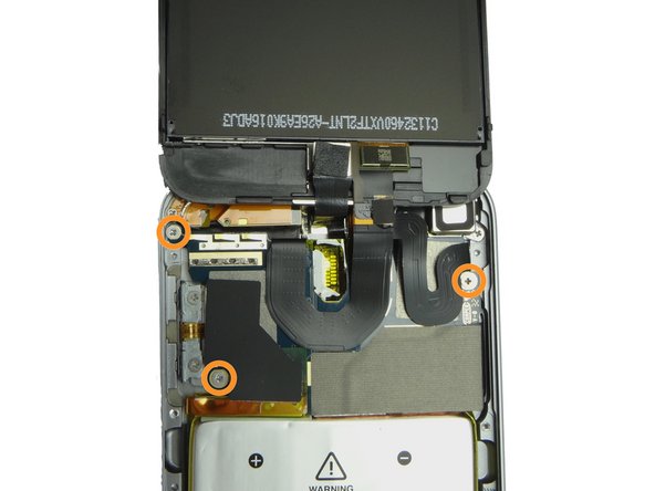
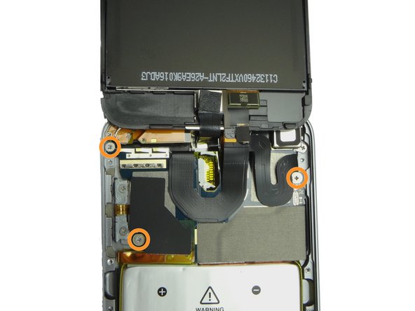
  10. Picture 3: Remove three 1.6 mm #00 Phillips screws securing the logic board to the rear case.  Place in SLOT 4.
    • Picture 3: Remove three 1.6 mm #00 Phillips screws securing the logic board to the rear case. Place in SLOT 4.

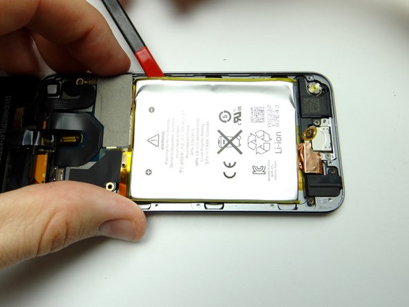
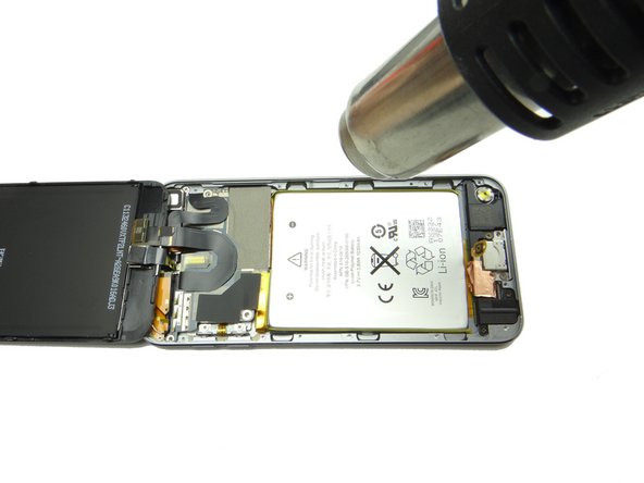
  11. Picture 1: Apply low-level heat in 30 second increments as needed to loosen the battery adhesive. Hold the heat gun three inches from the battery to avoid overheating. Picture 2: Use the spudger to pry up the upper right corner of the battery.
    • Picture 1: Apply low-level heat in 30 second increments as needed to loosen the battery adhesive.

    • Hold the heat gun three inches from the battery to avoid overheating.

    • Picture 2: Use the spudger to pry up the upper right corner of the battery.

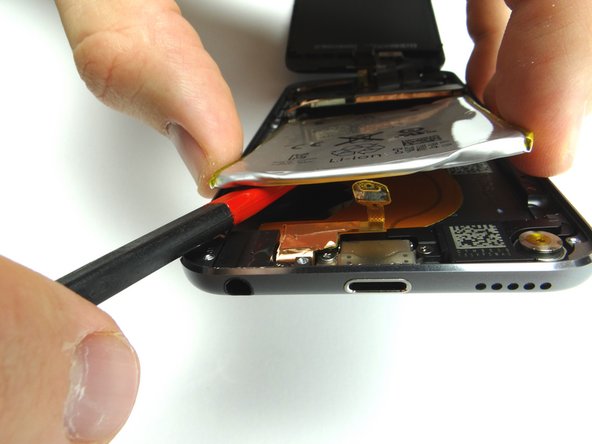
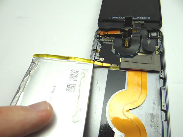
    • Picture 3: Work your way around the battery to free it, taking care not to tear the charging port cable underneath.

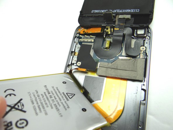
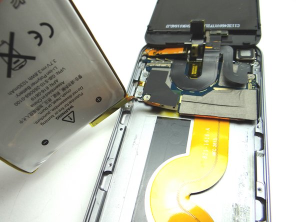
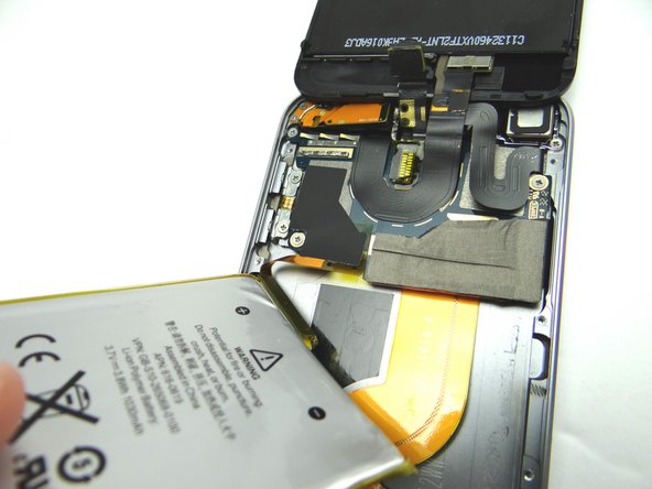
  12. Picture 1: Note the battery cable orientation. Pictures 1-3: Rotate battery clockwise to fold it away from iPod. Pictures 1-3: Rotate battery clockwise to fold it away from iPod.
    • Picture 1: Note the battery cable orientation.

    • Pictures 1-3: Rotate battery clockwise to fold it away from iPod.

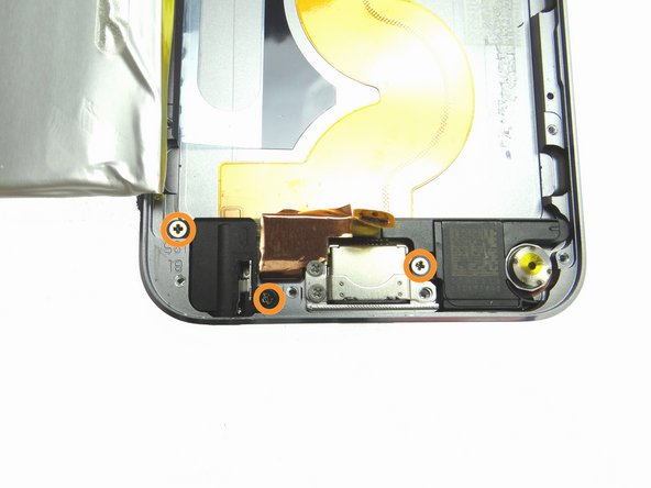
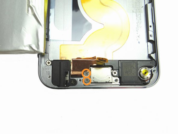
  13. Remove three 2.6 mm #00 Phillips screws.  Place in SLOT 5. You may have to remove a small piece of electrical tape covering right-hand screw holding the headset jack.
    • Remove three 2.6 mm #00 Phillips screws. Place in SLOT 5.

    • You may have to remove a small piece of electrical tape covering right-hand screw holding the headset jack.

    • Remove two 2.0 mm #00 Phillips screws. Place in SLOT 6.

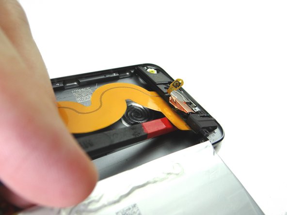
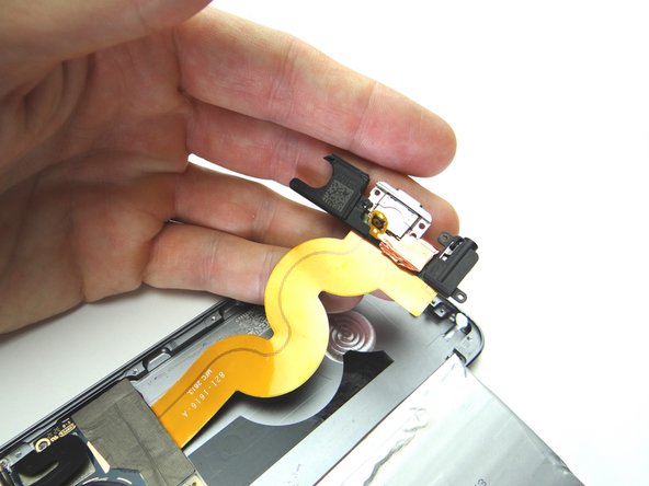
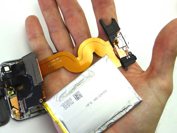
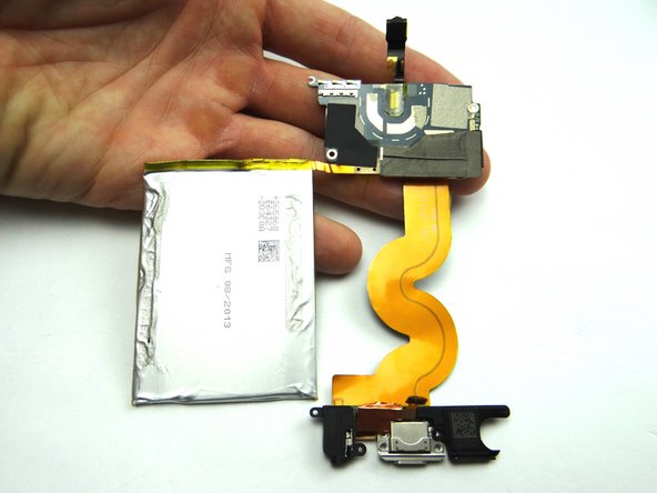
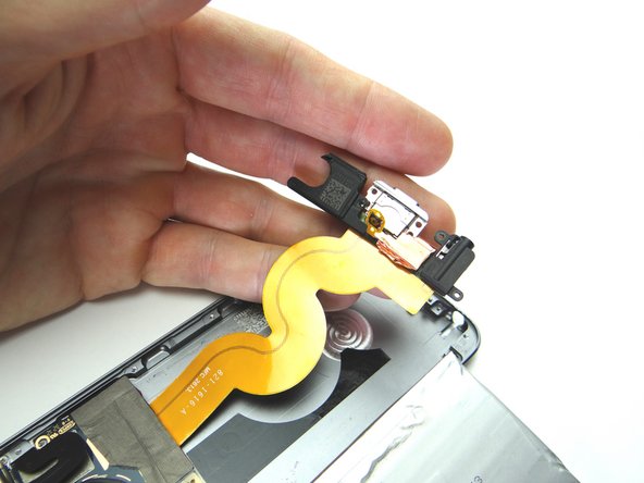
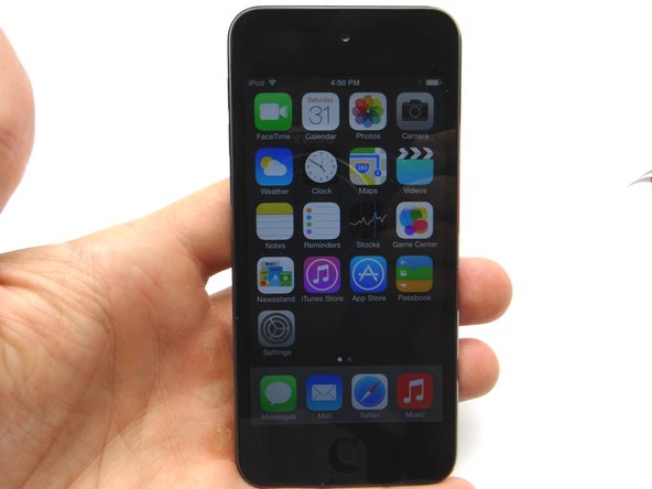
  14. Picture 1: Push the flat end of the spudger under the charging port ribbon cable and pry up until you're able to grab the assembly with your fingers. Picture 2: Use your fingers to carefully finish removing the assembly, noting the ribbon cable, headset jack, charging port and loudspeaker are all connected.
    • Picture 1: Push the flat end of the spudger under the charging port ribbon cable and pry up until you're able to grab the assembly with your fingers.

    • Picture 2: Use your fingers to carefully finish removing the assembly, noting the ribbon cable, headset jack, charging port and loudspeaker are all connected.

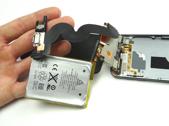
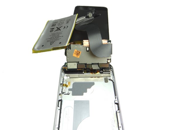
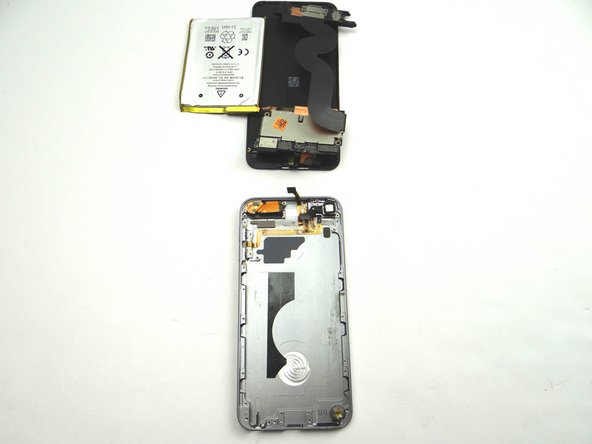
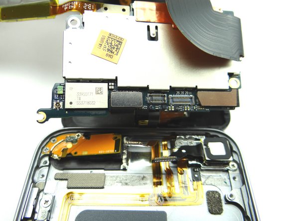
  15. Picture 1: With the battery and charging port assembly in hand, gently flip it over. Picture 2:  The underside of the logic board should now be exposed. Picture 3:  With the underside of the logic board exposed, rest the battery and charging port assembly by the screen.
    • Picture 1: With the battery and charging port assembly in hand, gently flip it over.

    • Picture 2: The underside of the logic board should now be exposed.

    • Picture 3: With the underside of the logic board exposed, rest the battery and charging port assembly by the screen.

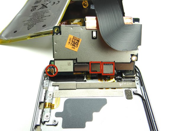
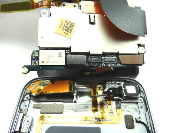
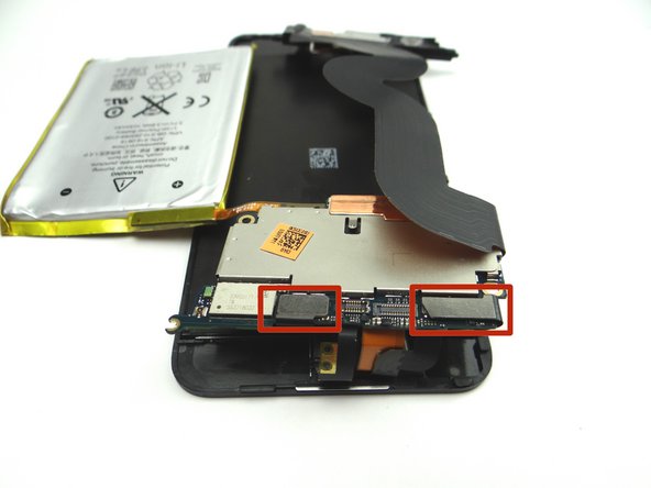
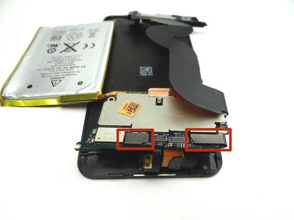
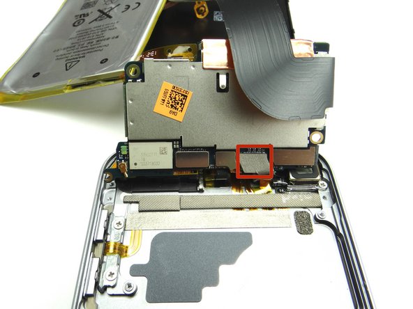
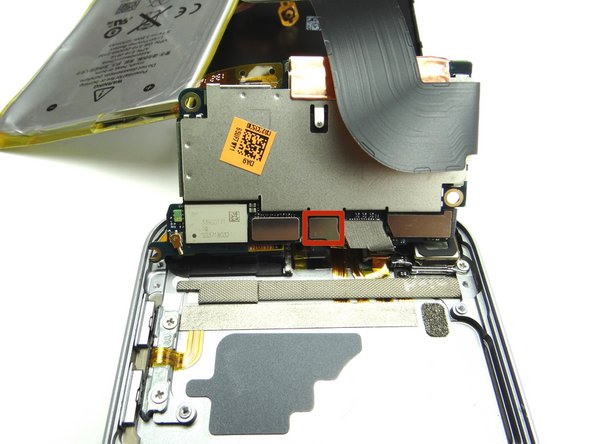
  16. In the next step, you'll disconnect the three pictured cables.
    • In the next step, you'll disconnect the three pictured cables.

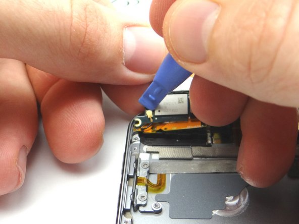
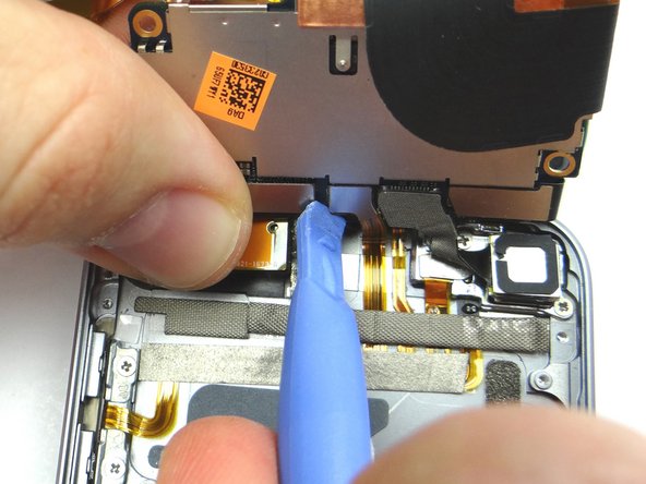
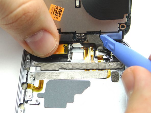
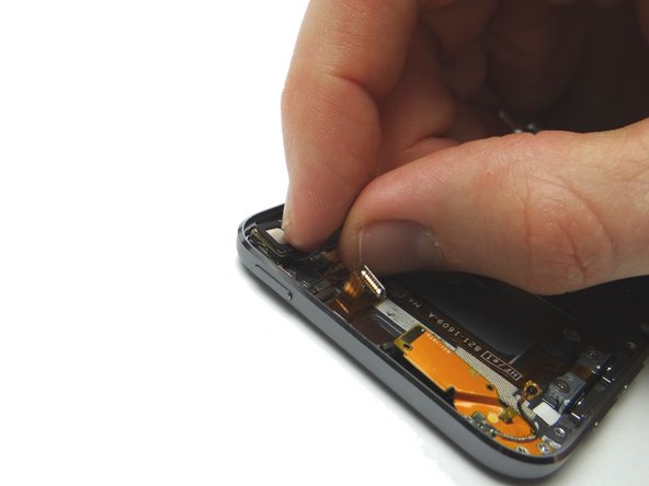
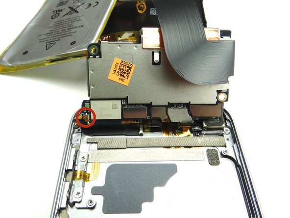
  17. Disconnect wifi antenna. Disconnect buttons cable. Disconnect rear camera cable.
    • Disconnect wifi antenna.

    • Disconnect buttons cable.

    • Disconnect rear camera cable.

    • Leave the LCD and digitizer cables attached.

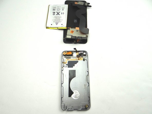
  18. With the three cables disconnected, you can now separate the front panel, logic board, battery and charging port assembly - as one unit - from the rear case. With the three cables disconnected, you can now separate the front panel, logic board, battery and charging port assembly - as one unit - from the rear case.
    • With the three cables disconnected, you can now separate the front panel, logic board, battery and charging port assembly - as one unit - from the rear case.

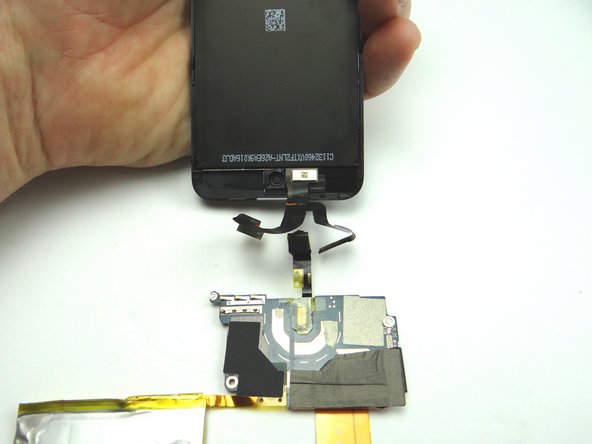
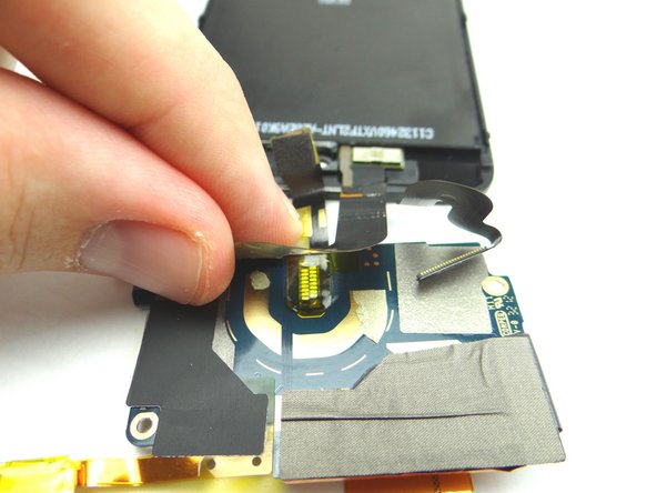
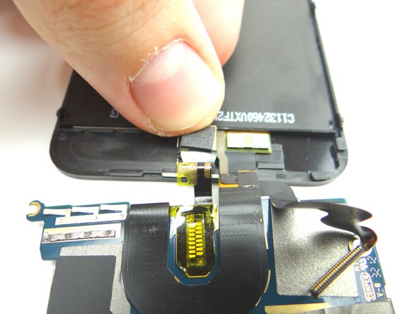
  19. Disconnect LCD and digitizer cables. Flip over the logic board and battery.  Disconnect front-facing camera. Peel up LCD cable from logic board.
    • Disconnect LCD and digitizer cables.

    • Flip over the logic board and battery. Disconnect front-facing camera.

    • Peel up LCD cable from logic board.

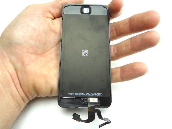
  20. The front panel can now be separated from the logic board.
    • The front panel can now be separated from the logic board.

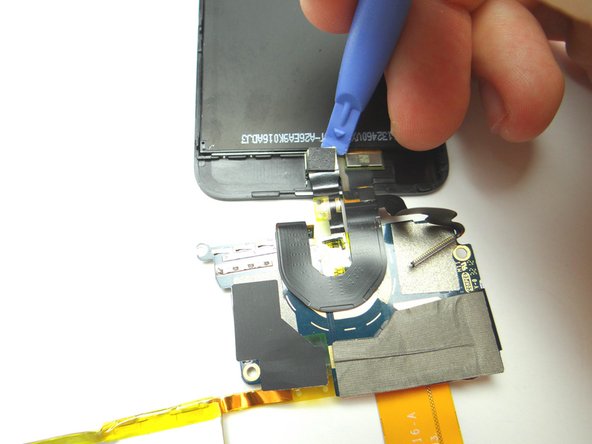
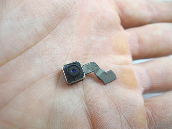
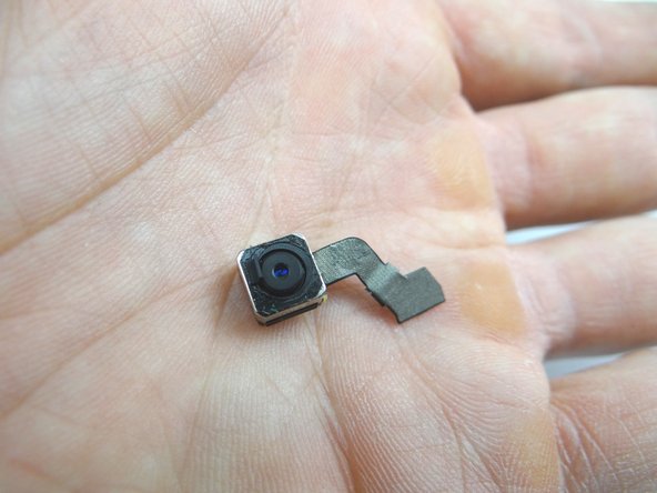
  21. Pictures 1 & 2: Peel up the camera cable then use the blue pry tool to remove the camera from its socket.  Place in COMPARTMENT B. Pictures 1 & 2: Peel up the camera cable then use the blue pry tool to remove the camera from its socket.  Place in COMPARTMENT B. Pictures 1 & 2: Peel up the camera cable then use the blue pry tool to remove the camera from its socket.  Place in COMPARTMENT B.
    • Pictures 1 & 2: Peel up the camera cable then use the blue pry tool to remove the camera from its socket. Place in COMPARTMENT B.

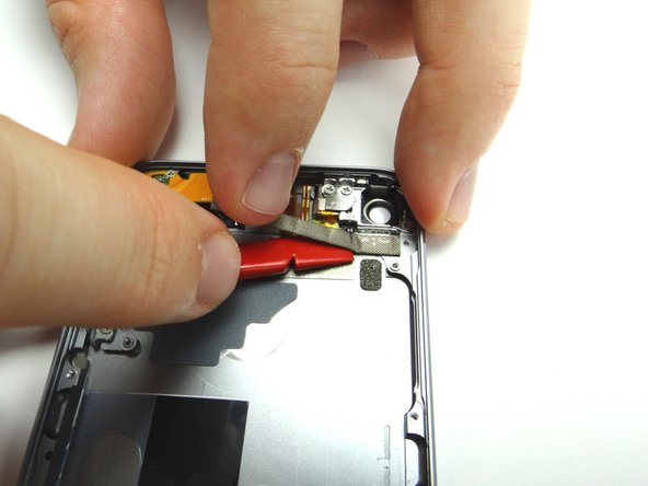
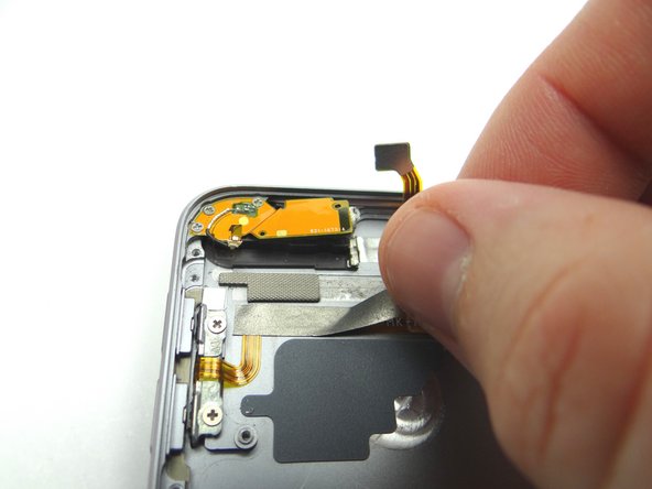
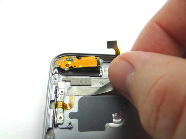
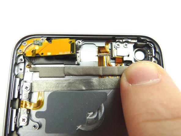
  22. Starting on the left, peel up the tape roll covering the buttons cable.  Place in COMPARTMENT C. Then starting on the right, peel up the strip of tape just below.  Place in COMPARTMENT C.
    • Starting on the left, peel up the tape roll covering the buttons cable. Place in COMPARTMENT C.

    • Then starting on the right, peel up the strip of tape just below. Place in COMPARTMENT C.

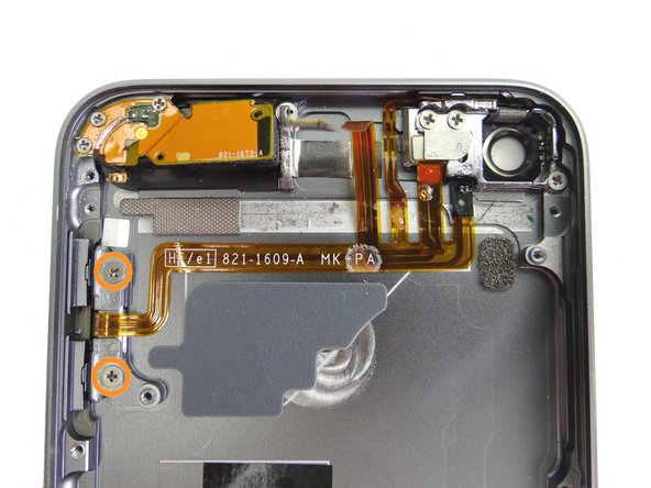
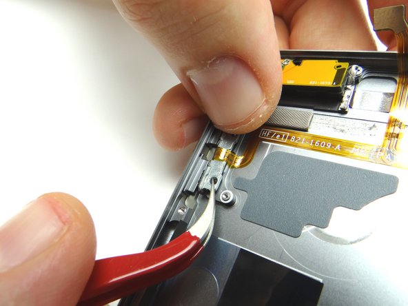
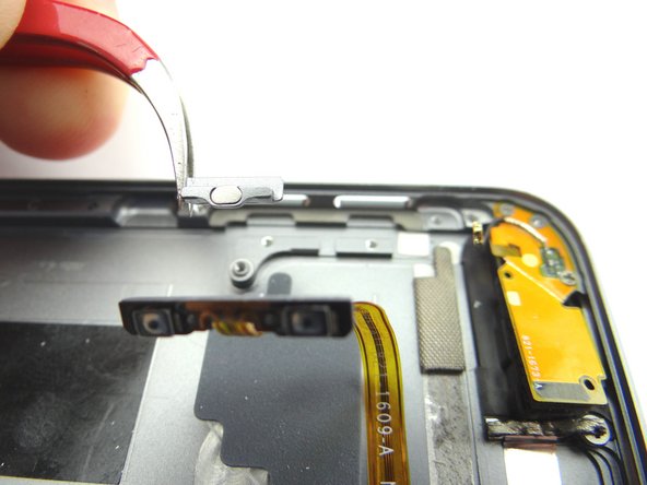
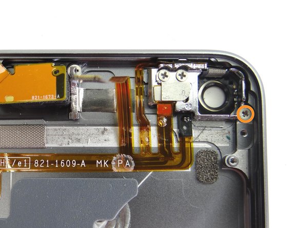
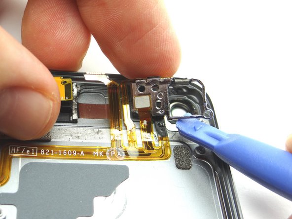
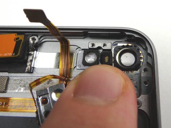
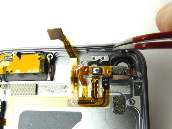
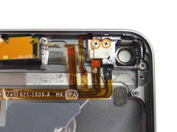
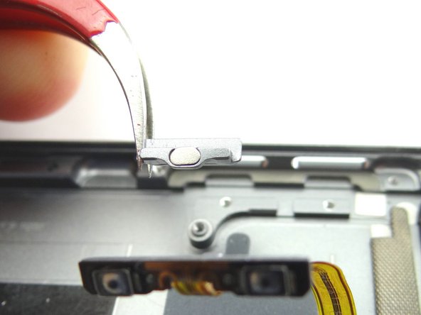
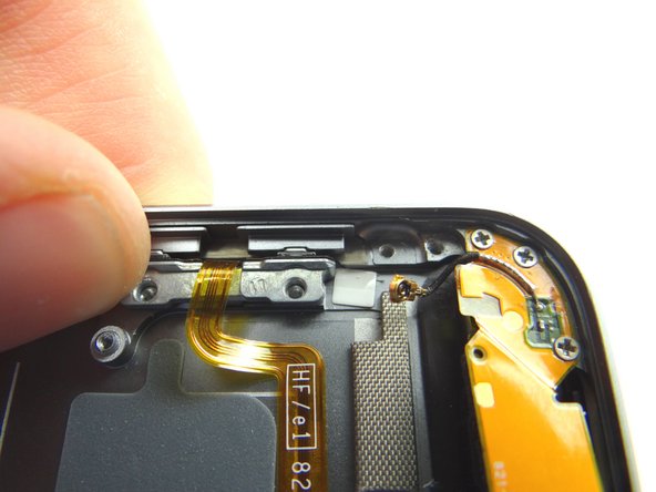
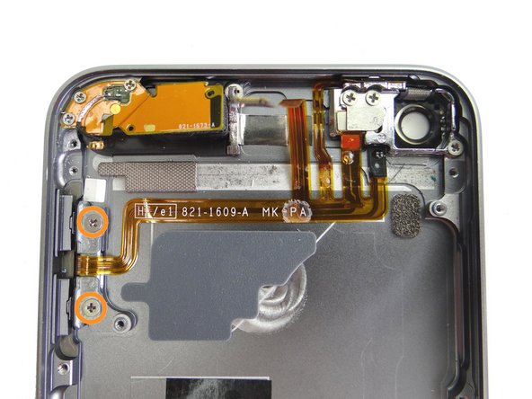
  23. Remove two 2.0 mm #00 Phillips screws securing the volume button end of the button ribbon cable to the rear case.  Place screws in SLOT 7. Use tweezers to lift volume button bracket out of the way just enough to allow the volume buttons to be extracted. Use tweezers to remove volume buttons. Place in COMPARTMENT D.
    • Remove two 2.0 mm #00 Phillips screws securing the volume button end of the button ribbon cable to the rear case. Place screws in SLOT 7.

    • Use tweezers to lift volume button bracket out of the way just enough to allow the volume buttons to be extracted.

    • Use tweezers to remove volume buttons. Place in COMPARTMENT D.

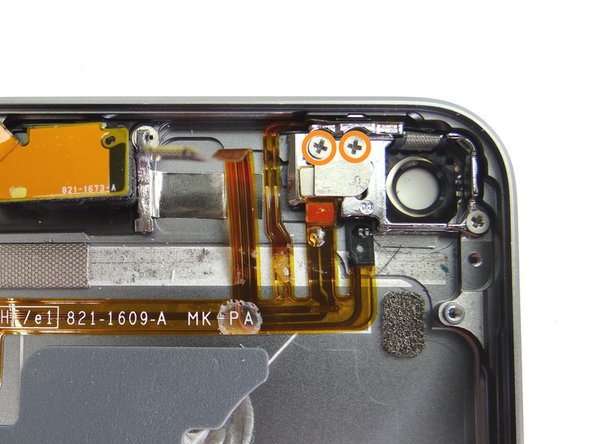
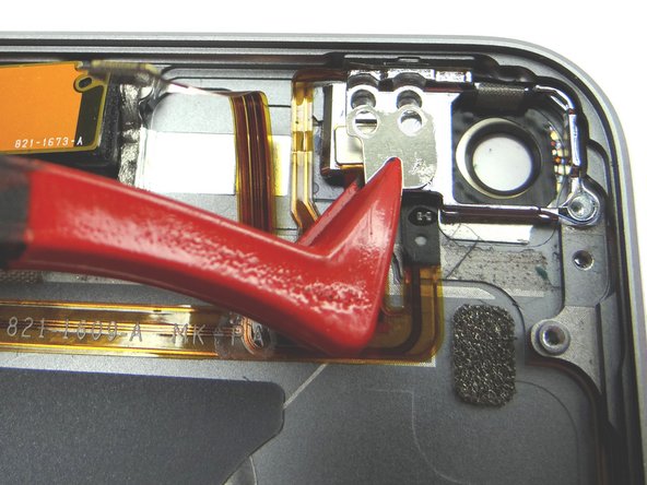
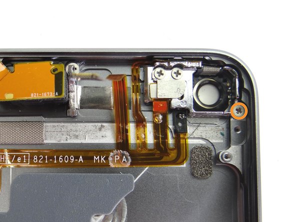
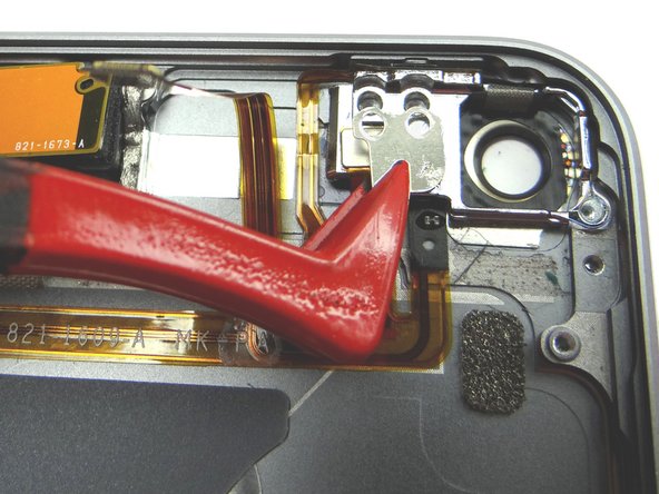
  24. Picture 1: Remove two 2.3 mm #00 Phillips screws.  Place screws in SLOT 8. Picture 2: Use plastic tweezers to remove small plate.  Place in COMPARTMENT E. Picture 3: Remove one 1.6 mm #00 Phillips screw.  Place screw in SLOT 9.
    • Picture 1: Remove two 2.3 mm #00 Phillips screws. Place screws in SLOT 8.

    • Picture 2: Use plastic tweezers to remove small plate. Place in COMPARTMENT E.

    • Picture 3: Remove one 1.6 mm #00 Phillips screw. Place screw in SLOT 9.

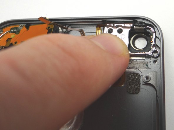
  25. Use the blue pry tool and your finger to pry up the rear camera socket.
    • Use the blue pry tool and your finger to pry up the rear camera socket.

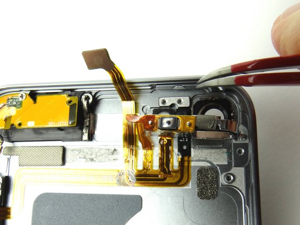
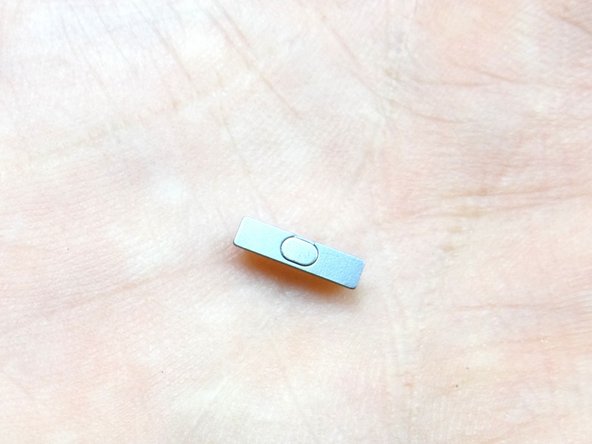
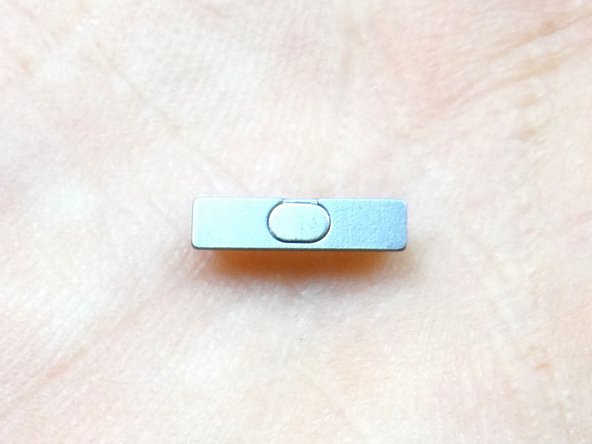
  26. Use metal tweezers to remove power button.  Place in COMPARTMENT E. Use metal tweezers to remove power button.  Place in COMPARTMENT E.
    • Use metal tweezers to remove power button. Place in COMPARTMENT E.

  27. Insert the spudger at the bottom of the microphone and push it  up to free it from the rear case. Grab the microphone with your fingers and continue peeling up
    • Insert the spudger at the bottom of the microphone and push it up to free it from the rear case.

    • Grab the microphone with your fingers and continue peeling up

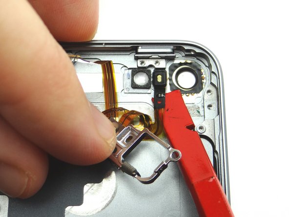
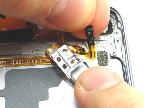
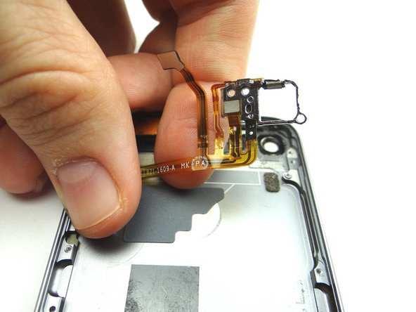
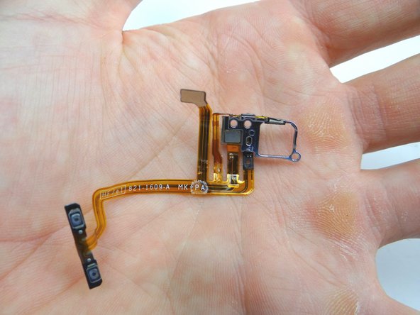
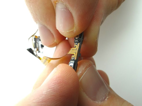
  28. Peel the power & volume button cable free from the rear case. Use the metal spudger to separate the volume button bracket from the volume button cable.  Place both in COMPARTMENT D (with volume buttons). Use the metal spudger to separate the volume button bracket from the volume button cable.  Place both in COMPARTMENT D (with volume buttons).
    • Peel the power & volume button cable free from the rear case.

    • Use the metal spudger to separate the volume button bracket from the volume button cable. Place both in COMPARTMENT D (with volume buttons).

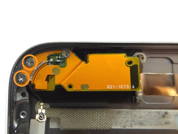
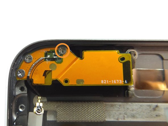
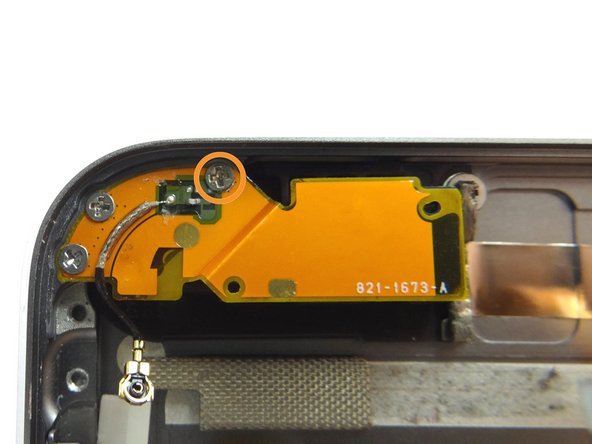
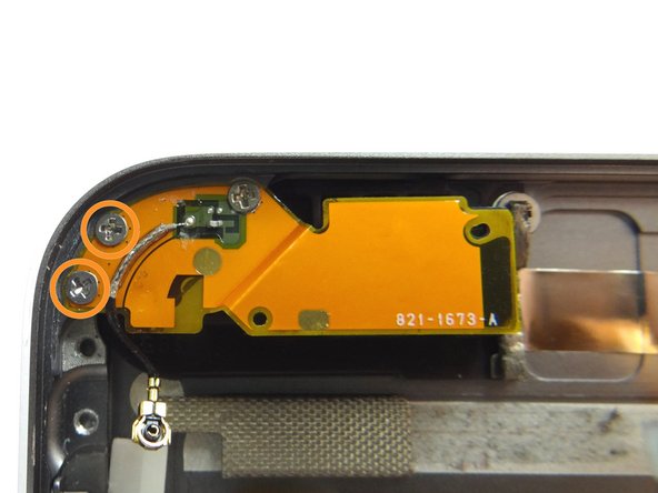
  29. Remove two 1.3 mm Phillips #00 screws.  Place in SLOT 10. Remove one 1.5 mm Phillips #00 screw.  Place in SLOT 11.
    • Remove two 1.3 mm Phillips #00 screws. Place in SLOT 10.

    • Remove one 1.5 mm Phillips #00 screw. Place in SLOT 11.

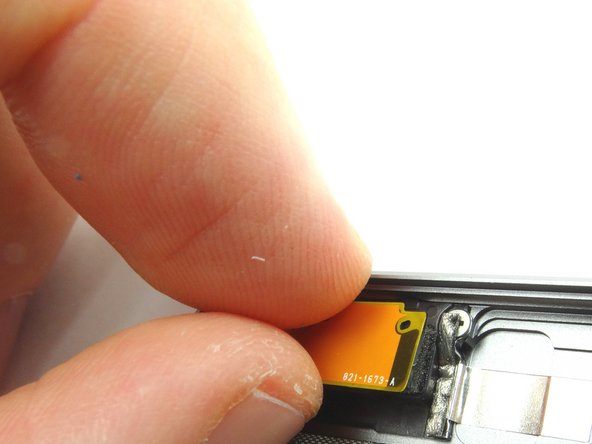
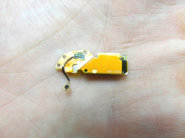
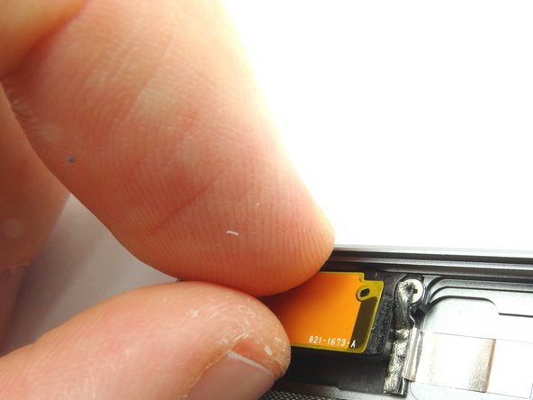
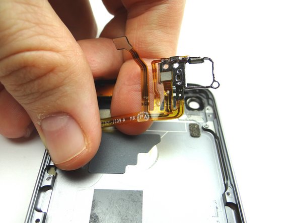
  30. Gently peel the antenna up from its foam adhesive backing.  Place in COMPARTMENT F. Gently peel the antenna up from its foam adhesive backing.  Place in COMPARTMENT F.
    • Gently peel the antenna up from its foam adhesive backing. Place in COMPARTMENT F.

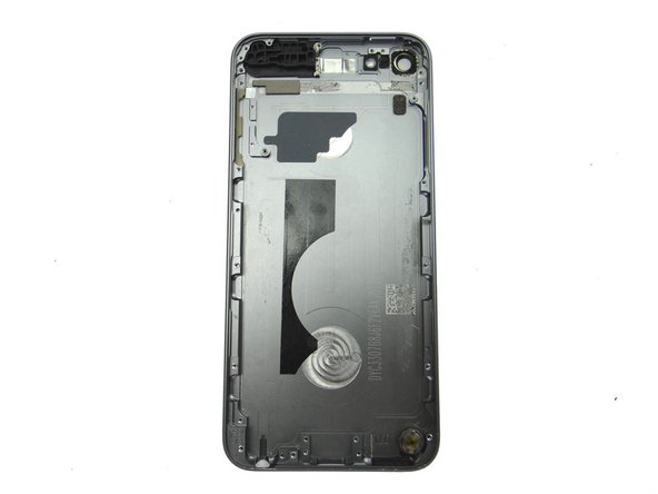
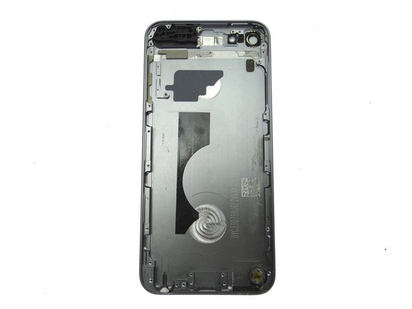
  31. Retrieve the rear case. Retrieve the rear case.
    • Retrieve the rear case.

  32. From COMPARTMENT F, push the wifi antenna firmly into place on the upper-left corner of the rear case. From COMPARTMENT F, push the wifi antenna firmly into place on the upper-left corner of the rear case.
    • From COMPARTMENT F, push the wifi antenna firmly into place on the upper-left corner of the rear case.

  33. Replace one 1.5 mm Phillips #00 screw from SLOT 11. Replace two 1.3 mm Phillips #00 screws from SLOT 10.
    • Replace one 1.5 mm Phillips #00 screw from SLOT 11.

    • Replace two 1.3 mm Phillips #00 screws from SLOT 10.

  34. From COMPARTMENT D, attach volume buttons bracket to volume buttons cable. From COMPARTMENT D, attach volume buttons bracket to volume buttons cable.
    • From COMPARTMENT D, attach volume buttons bracket to volume buttons cable.

  35. Picture 1: Place power and volume buttons cable on rear frame. Picture 2: Seat microphone, but don't seat the volume buttons bracket or rear camera socket.
    • Picture 1: Place power and volume buttons cable on rear frame.

    • Picture 2: Seat microphone, but don't seat the volume buttons bracket or rear camera socket.

  36. Picture 1: Retrieve the power button from COMPARTMENT E.  Maintain the orientation when seating the power button. Use tweezers to seat the power button. Seat rear camera frame.
    • Picture 1: Retrieve the power button from COMPARTMENT E. Maintain the orientation when seating the power button.

    • Use tweezers to seat the power button.

    • Seat rear camera frame.

  37. Picture 1: Replace one 1.6 mm #00 Phillips screw from SLOT 9. Picture 2: Replace metal plate from COMPARTMENT E. Picture 3: Replace two 2.3 mm #00 Phillips screws from SLOT 8.
    • Picture 1: Replace one 1.6 mm #00 Phillips screw from SLOT 9.

    • Picture 2: Replace metal plate from COMPARTMENT E.

    • Picture 3: Replace two 2.3 mm #00 Phillips screws from SLOT 8.

  38. Picture 1: From COMPARTMENT D, replace volume buttons.  Note the orientation when seating. Seat volume buttons bracket. Replace two 2.0 mm #00 Phillips screws securing the volume button end of the button ribbon cable to the rear case from SLOT 7.
    • Picture 1: From COMPARTMENT D, replace volume buttons. Note the orientation when seating.

    • Seat volume buttons bracket.

    • Replace two 2.0 mm #00 Phillips screws securing the volume button end of the button ribbon cable to the rear case from SLOT 7.

  39. Use your fingers to place both tape rolls from COMPARTMENT C. Use your fingers to place both tape rolls from COMPARTMENT C.
    • Use your fingers to place both tape rolls from COMPARTMENT C.

  40. From COMPARTMENT B, seat the camera in its socket on the rear case. From COMPARTMENT B, seat the camera in its socket on the rear case.
    • From COMPARTMENT B, seat the camera in its socket on the rear case.

  41. Reconnect the logic board to front panel: Reconnect the logic board to front panel: Reconnect the logic board to front panel:
    • Reconnect the logic board to front panel:

  42. Picture 1: Seat the LCD cable on logic board. Picture 2: Push the front-facing camera into its slot on the front panel. Picture 3: Flip the logic board and battery over to reconnect the LCD and digitizer cables.
    • Picture 1: Seat the LCD cable on logic board.

    • Picture 2: Push the front-facing camera into its slot on the front panel.

    • Picture 3: Flip the logic board and battery over to reconnect the LCD and digitizer cables.

  43. Attach rear case to the front panel, logic board, battery and charging port assembly over the next few steps. Attach rear case to the front panel, logic board, battery and charging port assembly over the next few steps.
    • Attach rear case to the front panel, logic board, battery and charging port assembly over the next few steps.

  44. Use your fingers to: Picture 1: Connect rear camera cable. (Remove it from its seat, connect it, and reseat it, if necessary). Picture 2: Connect buttons cable.
    • Use your fingers to:

    • Picture 1: Connect rear camera cable. (Remove it from its seat, connect it, and reseat it, if necessary).

    • Picture 2: Connect buttons cable.

    • Picture 3: Connect wifi antenna.

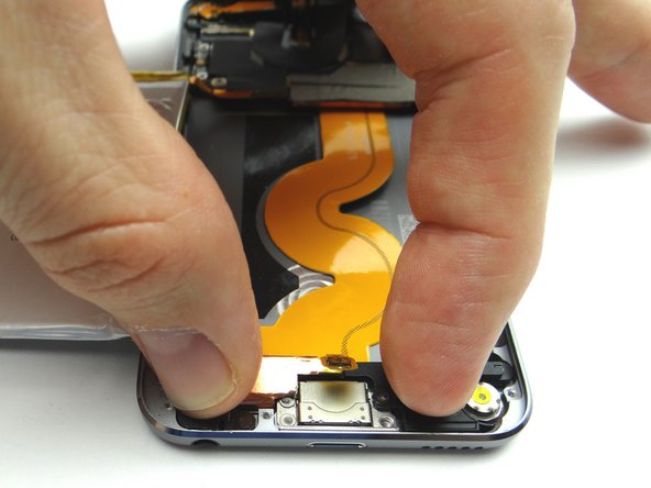
  45. Picture 1: Flip charging port, battery, and logic board over. Picture 2: Seat the charging port. Picture 3: Rotate battery counter-clockwise into place.
    • Picture 1: Flip charging port, battery, and logic board over.

    • Picture 2: Seat the charging port.

    • Picture 3: Rotate battery counter-clockwise into place.

  46. Picture 1: Make sure the home button contact isn't trapped underneath the battery. Picture 2: Replace two 2.0 mm #00 Phillips screws from SLOT 6. Picture 3: Replace three 2.6 mm #00 Phillips screws from SLOT 5.
    • Picture 1: Make sure the home button contact isn't trapped underneath the battery.

    • Picture 2: Replace two 2.0 mm #00 Phillips screws from SLOT 6.

    • Picture 3: Replace three 2.6 mm #00 Phillips screws from SLOT 5.

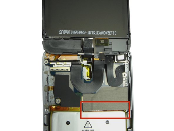
  47. Picture 1: Make sure the tape hanging over the bottom edge of the logic board covers the top edge of the battery. (The device won't close properly otherwise). Picture 2: Replace three 1.6 mm #00 Phillips from SLOT 4. Picture 3: Seat front camera.
    • Picture 1: Make sure the tape hanging over the bottom edge of the logic board covers the top edge of the battery. (The device won't close properly otherwise).

    • Picture 2: Replace three 1.6 mm #00 Phillips from SLOT 4.

    • Picture 3: Seat front camera.

  48. Replace metal plate from ZONE I, careful to feed home button contact through its slot at bottom.
    • Replace metal plate from ZONE I, careful to feed home button contact through its slot at bottom.

  49. Picture 1: Replace one 2.3 mm #00 Phillips screw from SLOT 3. Picture 2: Replace nine 1.6 mm #00 Phillips screws from SLOT 2. Picture 3: Replace two 1.2 mm #00 Phillips screws from SLOT 1.
    • Picture 1: Replace one 2.3 mm #00 Phillips screw from SLOT 3.

    • Picture 2: Replace nine 1.6 mm #00 Phillips screws from SLOT 2.

    • Picture 3: Replace two 1.2 mm #00 Phillips screws from SLOT 1.

  50. Seat the home button contact and cable.
    • Seat the home button contact and cable.

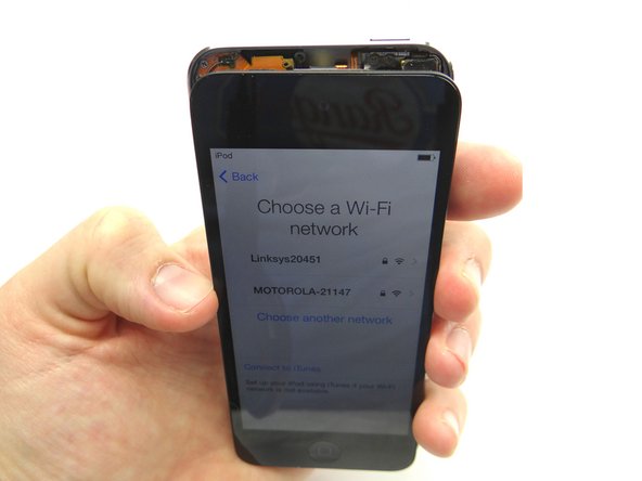
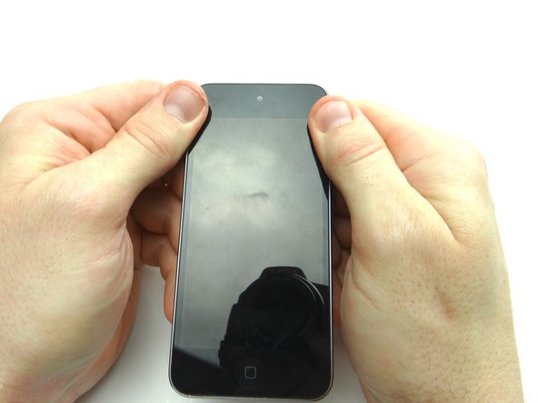
  51. Picture 1: Power up the device and test the LCD and digitizer before closing it. After reassembling an iPod, it is common to see a screen with lines down the LCD or a white screen.  Try turning it off and back on.  If that doesn't work, you may have to perform a soft reset. (press and hold power and home buttons simultaneously for ten seconds). Picture 2: Place the clips at the top of the front panel before seating the rest of front panel.
    • Picture 1: Power up the device and test the LCD and digitizer before closing it.

    • After reassembling an iPod, it is common to see a screen with lines down the LCD or a white screen. Try turning it off and back on. If that doesn't work, you may have to perform a soft reset. (press and hold power and home buttons simultaneously for ten seconds).

    • Picture 2: Place the clips at the top of the front panel before seating the rest of front panel.

    • Picture 3: Finish seating the remaining clips in the next step.

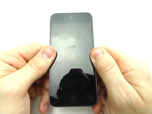
  52. Press the front panel clips into the rear frame, starting at the top and working your way down. Press firmly on either side of the home button where the adhesive pads are located. Press firmly on either side of the home button where the adhesive pads are located.
    • Press the front panel clips into the rear frame, starting at the top and working your way down.

    • Press firmly on either side of the home button where the adhesive pads are located.

  53. Power up and test the device. Power up and test the device.
    • Power up and test the device.

Finish Line
James Linder

Member since: 01/24/2013

71,591 Reputation

217 Guides authored

0 Comments

Add Comment

View Statistics:

Past 24 Hours: 0

Past 7 Days: 0

Past 30 Days: 0

All Time: 61

CELL PHONE SANDBOX