-
-
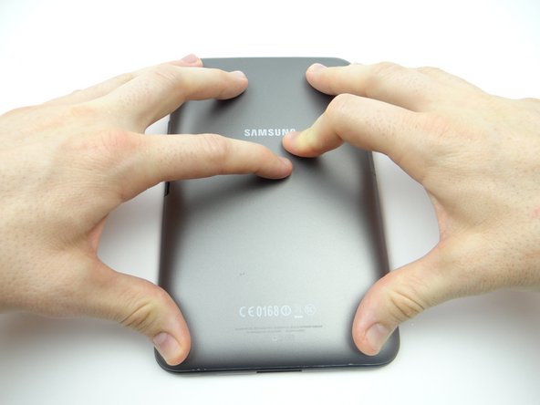
Power down device.
-
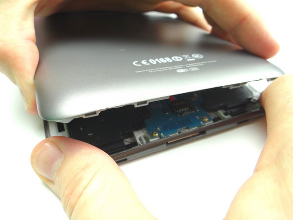
Remove SD card. Place in COMPARTMENT A.
-
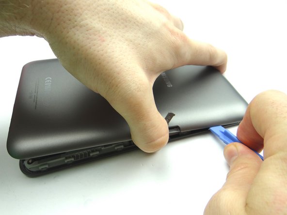
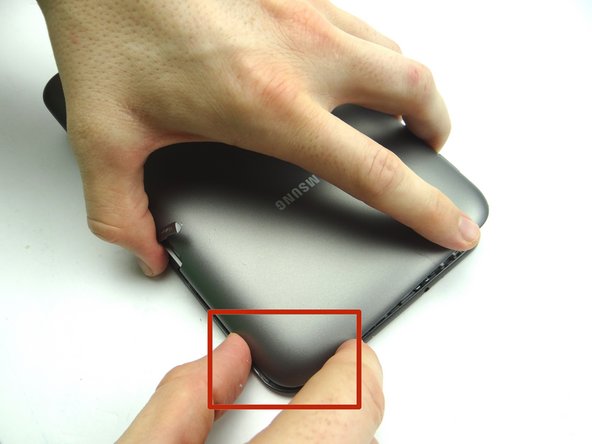
In the next few steps, you'll be removing the battery cover by freeing the clips marked in Picture 3.
-
-
-
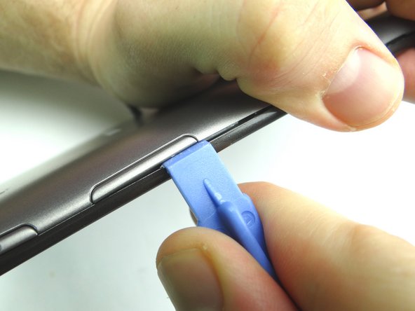
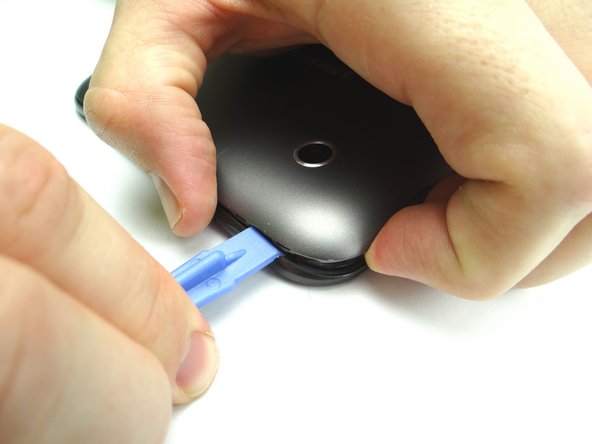
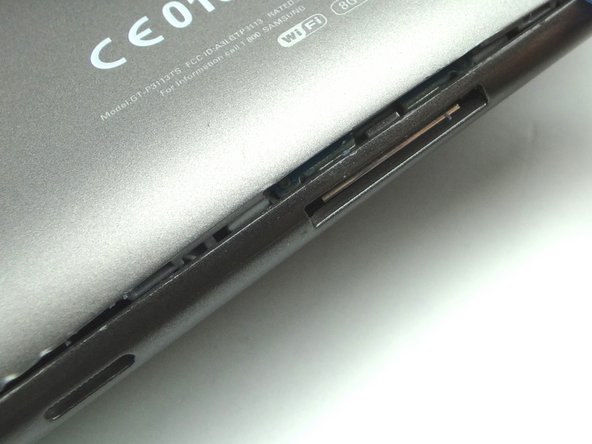
Picture 1: Insert wide blue pry tool below the bottom half of the volume rocker.
-
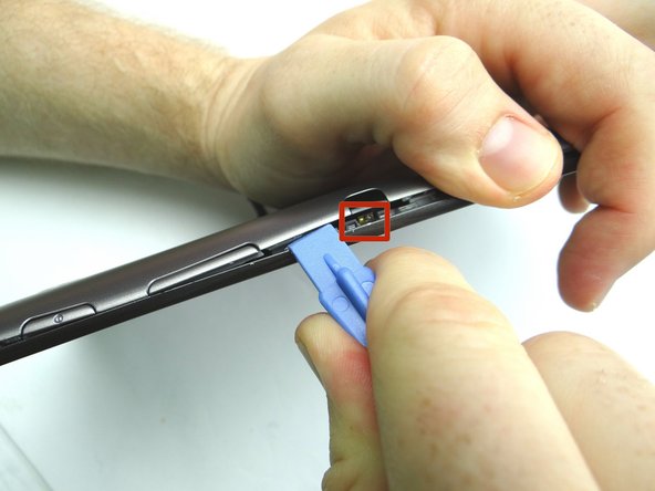
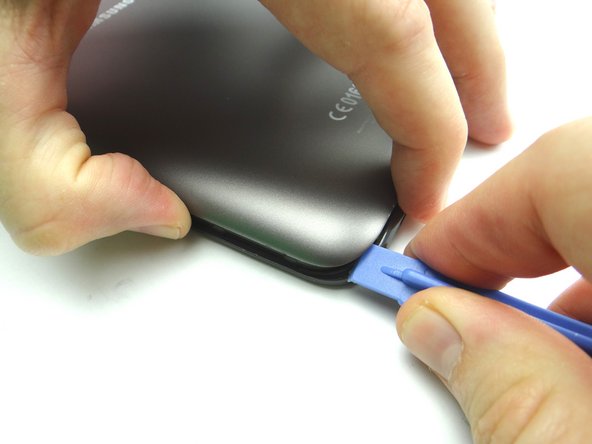
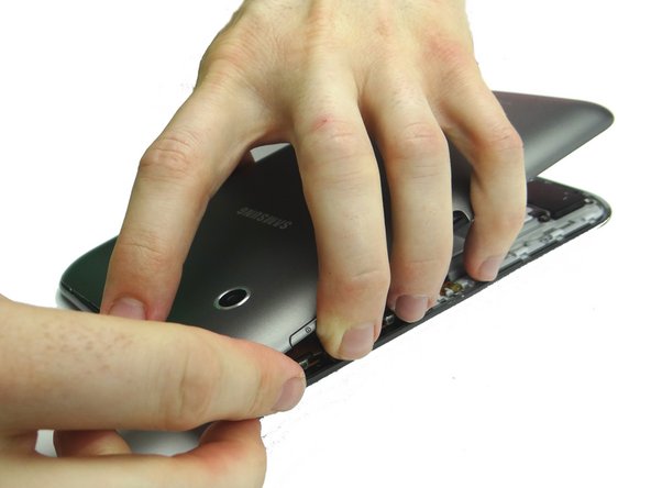
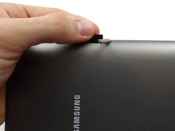
Picture 2: Sweep between the volume rocker and infrared sensor cover. Twist counter-clockwise to pop up. Grab the battery cover with your thumb to hold it open.
-
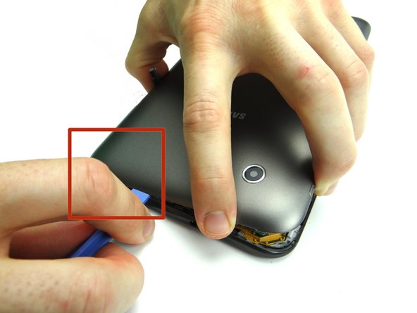
Don't sweep past the infrared sensor (red square in Picture 2).
-
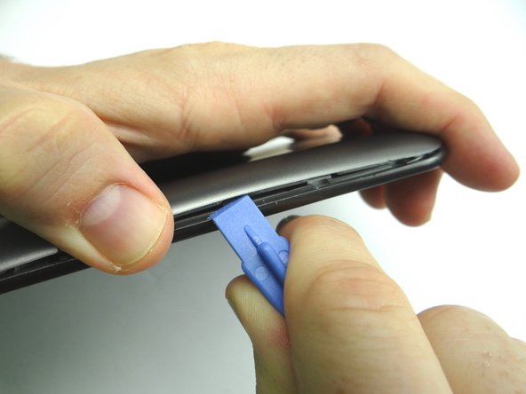
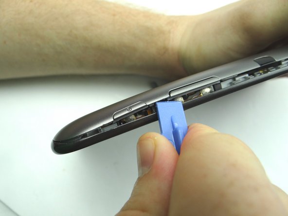
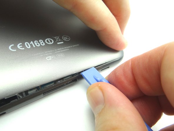
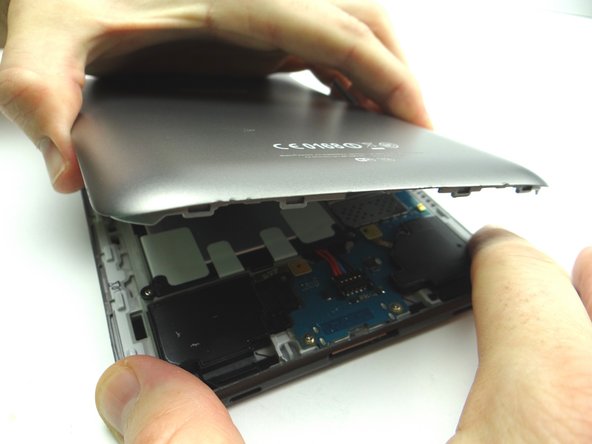
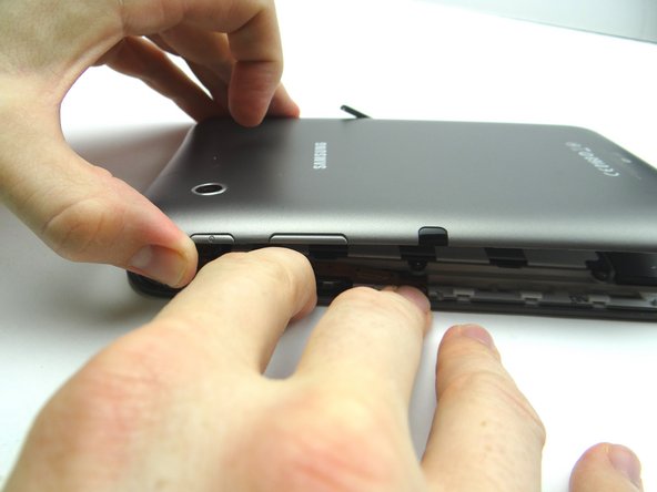
Picture 3: Reinsert the wide blue pry tool half an inch past the infrared sensor and continue working your way down towards the corner. Continue peeling up with your thumb in the opposite hand.
-
-
-
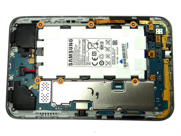
Remove six 3.4 mm Phillips #00 screws holding down the battery. Place in SLOT 1.
-
-
-
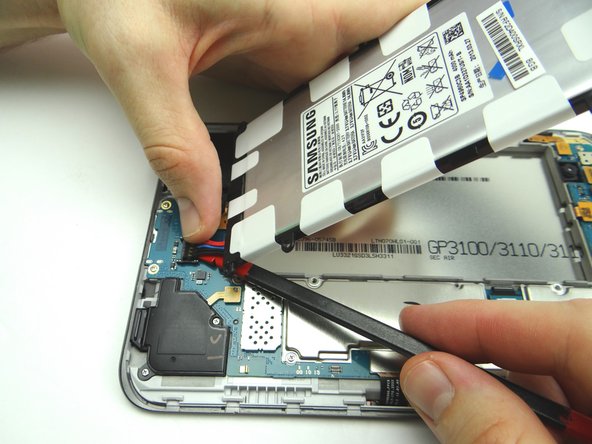
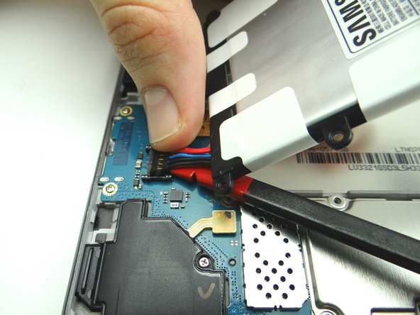
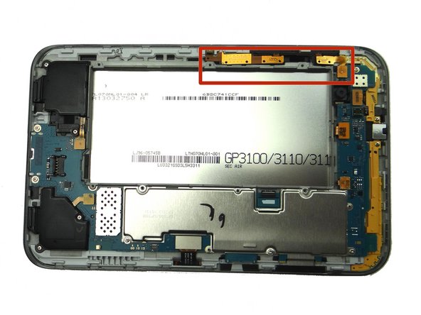
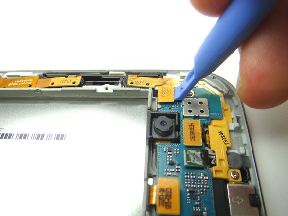
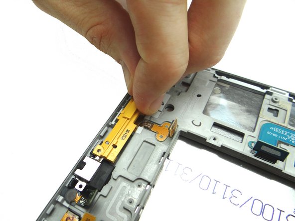
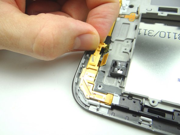
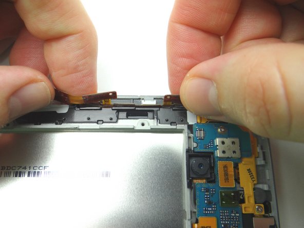
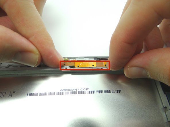
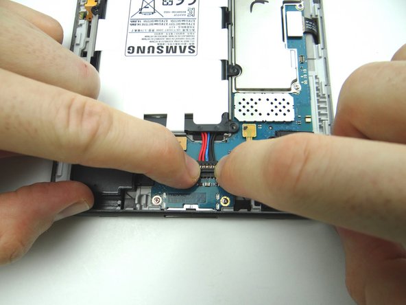
Pictures 1 & 2: Disconnect power / volume / infrared sensor cable.
-
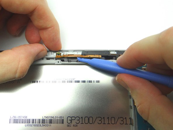
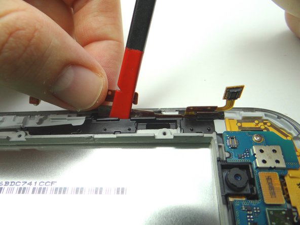
Picture 3: Lift cable into upright position.
-
-
-
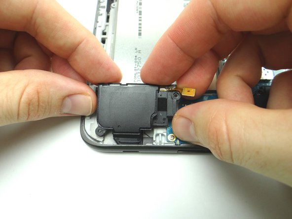
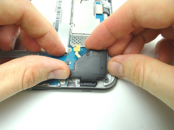
Use the blue pry tool to disconnect the left and right speakers.
-
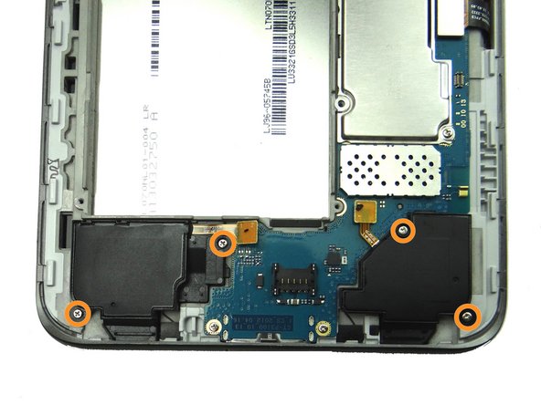
Remove four 3.4 mm #00 Phillips screws. Place in SLOT 1.
-
Place speakers in ZONE I.
-
-
-
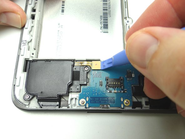
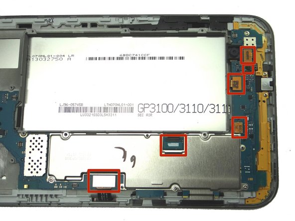
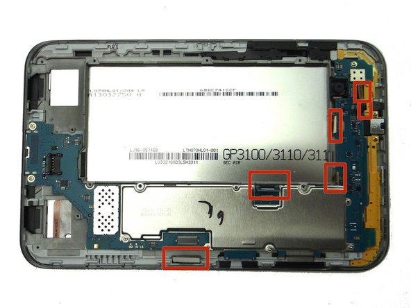
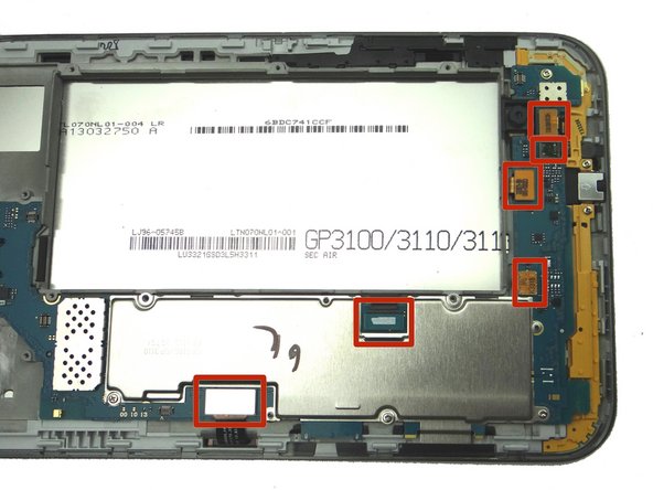
Disconnect (top to bottom):
-
Front-facing camera
-
Headphone jack & Microphone assembly
-
Rear Camera
-
Contact pad
-
LCD
-
Digitizer
-
-
-
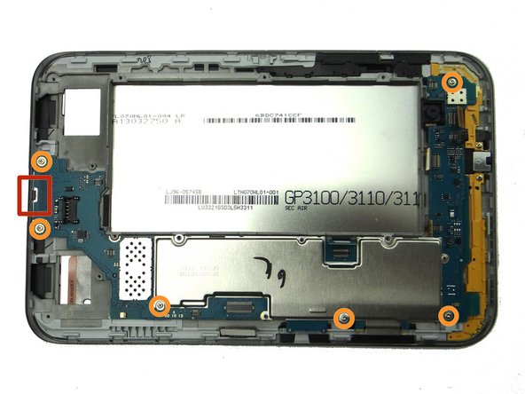
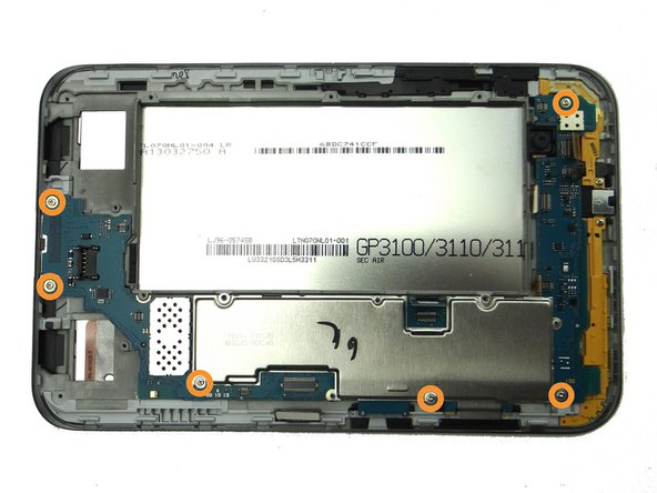
Picture 1: Remove six 3.4 mm #00 Phillips screws. Place in SLOT 1.
-
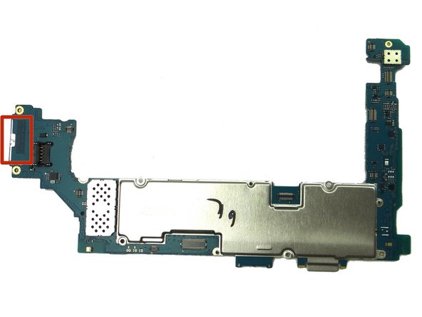
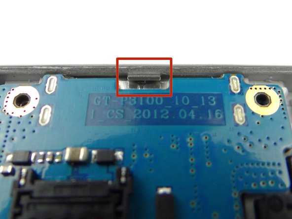
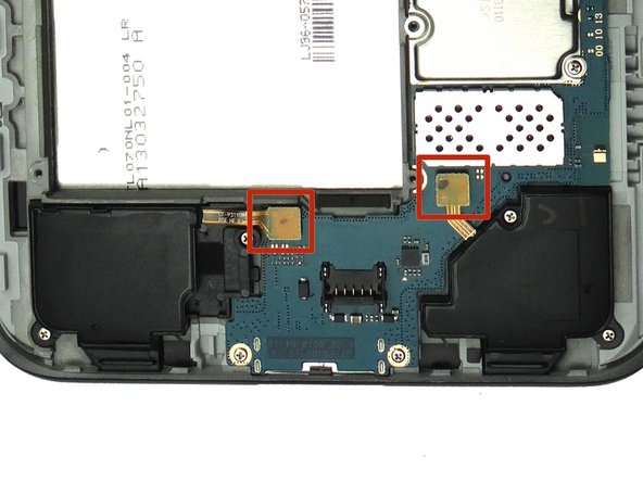
Picture 2: Be aware that the charging port is situated under a ledge as you remove it (red square in Picture 1 & 2).
-
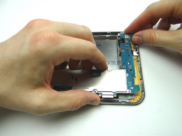
Picture 3: Lift top of logic board first as you guide it up and over the top edge of the front panel.
-
Make space for the logic board on the anti-static foam, away from the battery.
-
-
-
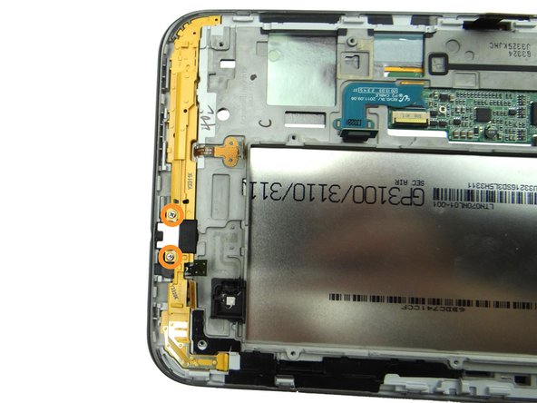
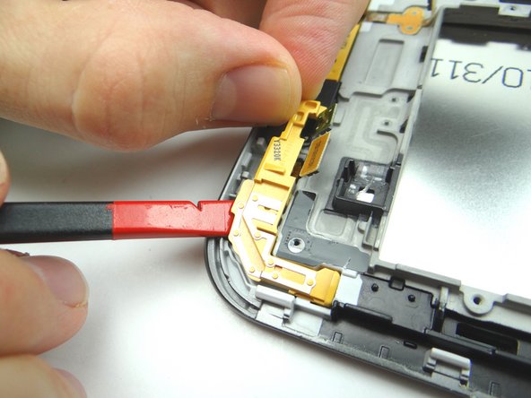
Picture 1: Remove two 3.4 mm #00 Phillips screws. Place in SLOT 1.
-
Picture 2: Lift corner bracket with spudger and fingers. Place in ZONE I.
-
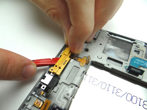
Picture 3: Lift opposite corner bracket and place in ZONE II.
-
-
-
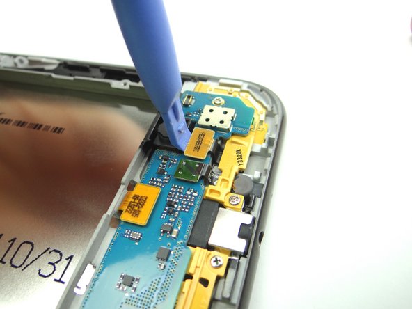
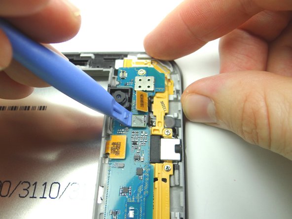
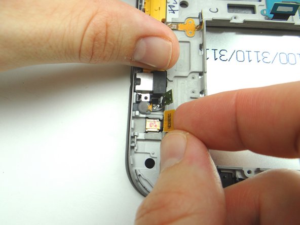
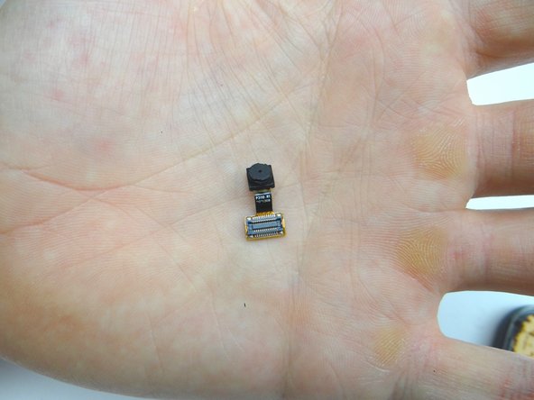
Lift front-facing camera slightly, then peel away from its socket.
-
Place in COMPARTMENT D.
-
-
-
Replace logic board:
-
Seat charging port first, under the tiny ledge in (red square Picture 2).
-
Make sure no cables get trapped below the logic board.
-
-
-
Seat the left and right speakers.
-
Replace four 3.4 mm #00 Phillips screws from SLOT 1.
-
-
-
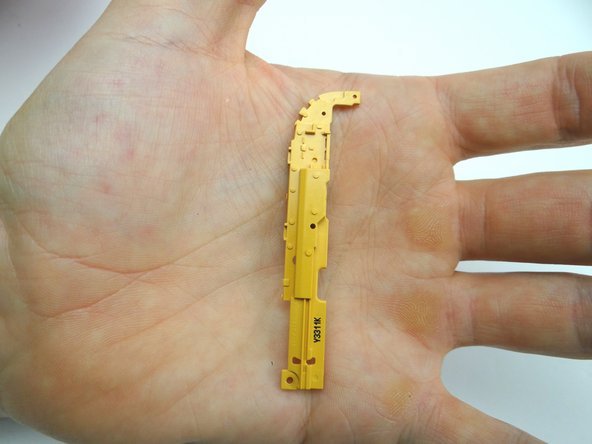
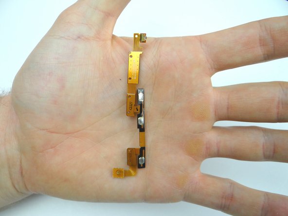
From COMPARTMENT C, replace power / volume / Infrared cable.
-
Adhere the cable to the black wall of the front panel.
-
Make sure the cable is properly aligned against the wall and that the tiny mounting tabs are all poking through the holes in the cable (seven in all).
-
-
-
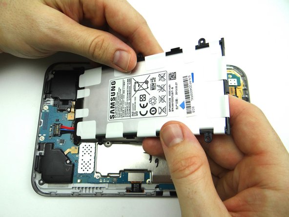
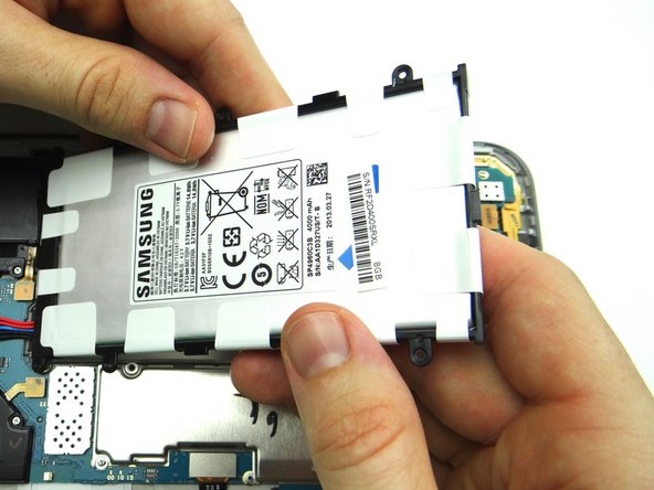
Seat the battery.
-
Connect the battery by pushing straight down on the entirety of the connector.
-
Replace six 3.4 mm Phillips #00 screws from SLOT 1.
-
-
-
Picture 1: Seat this corner first.
-
Picture 2: Continue seating top edge.
-
Picture 3: Make sure the power button and volume rocker seat properly and you push the sides into place.
-