-
-
Power down the device.
-
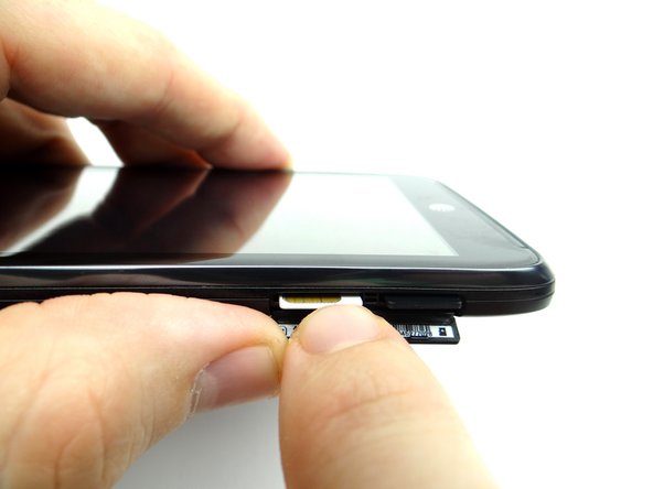
Open the SIM tray slot. Push the SIM card in and it will pop out. Repeat with the SD card, if present. Place both in COMPARTMENT A.
-
-
-
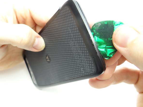
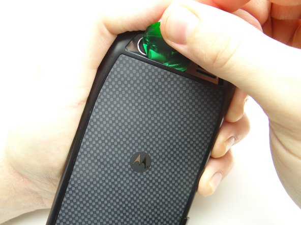
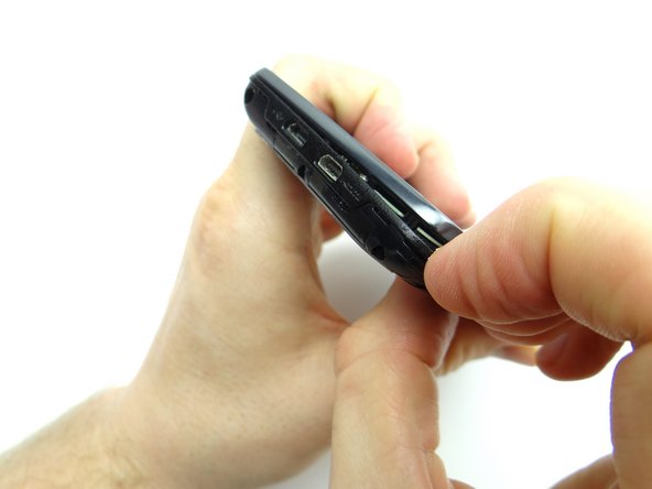
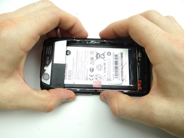
Insert guitar pick in the upper-right corner between the battery cover and display assembly.
-
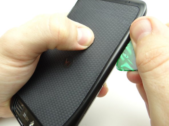
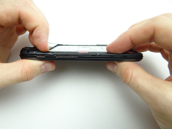
Work your way down the right side to release clips holding the battery cover in place.
-
-
-
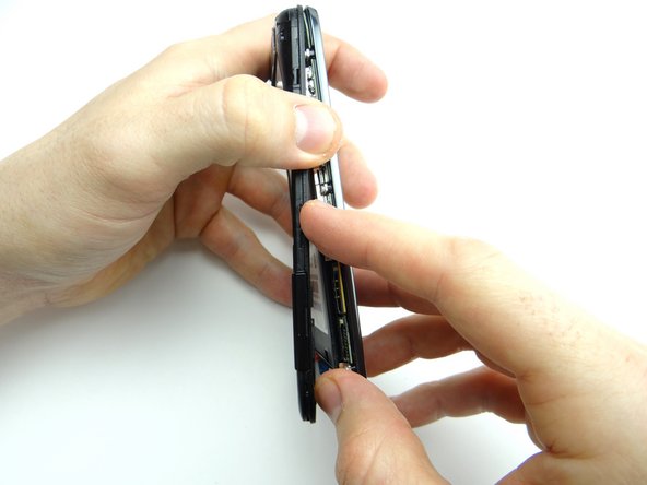
Work your way across the bottom, then up the opposite side to continue releasing clips.
-
-
-
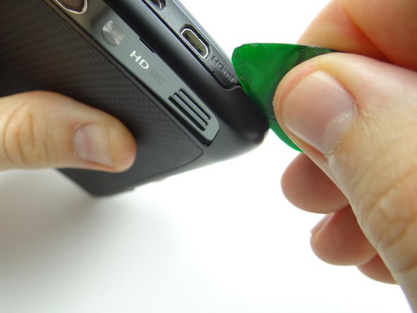
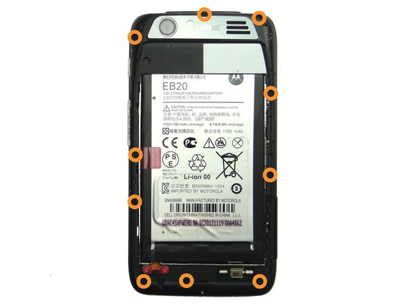
Be careful while performing this step:
-
Picture 1: Release the battery cover clips near the HDMI port.
-
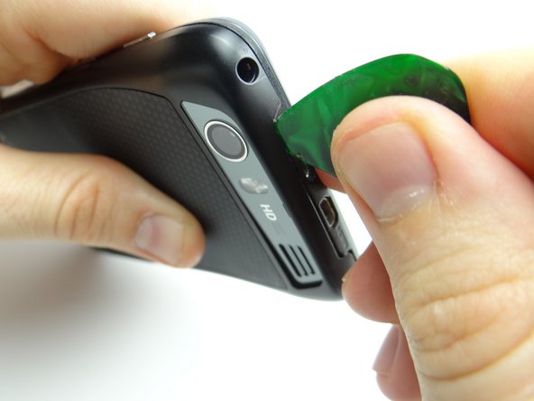
Picture 2: Release clips behind the charging and HDMI ports.
-
Picture 3: Release clips below rear camera trim.
-
-
-
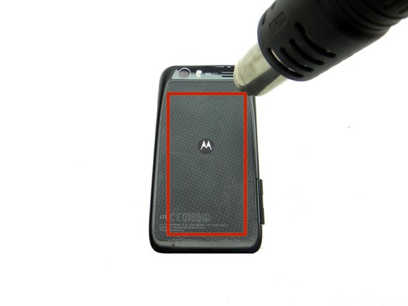
Adhesive holds the battery cover in place. Don't try to remove the battery cover just yet:
-
Picture 1: Heat the battery cover with low-level (100° Celsius heat) for 30 seconds.
-
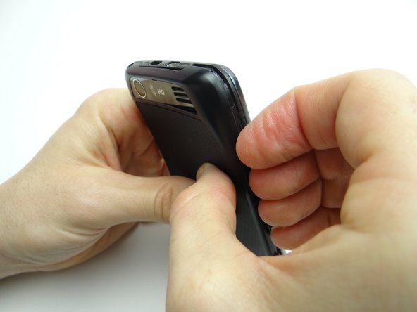
Picture 2: Use your fingers to peel away the battery cover slightly.
-
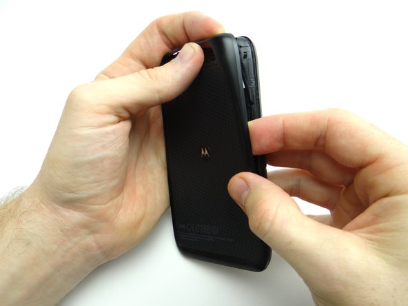
Picture 3: Push your finger under the Motorola symbol.
-
The Motorola symbol will stay adhered to the battery as you remove the battery cover if you're not careful!
-
-
-
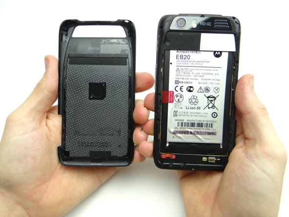
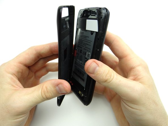
Continue peeling off battery cover, releasing the clips holding it in place.
-
Place battery cover in ZONE I.
-
-
-
Picture 1: Remove ten 4.8mm T5 Torx screws. Place in SLOT 1.
-
Picture 2: Begin separating the mid-frame from the front panel in the upper-left hand corner (opposite the headphone jack).
-
Picture 3: Continue working down the side, opposite the buttons.
-
-
-
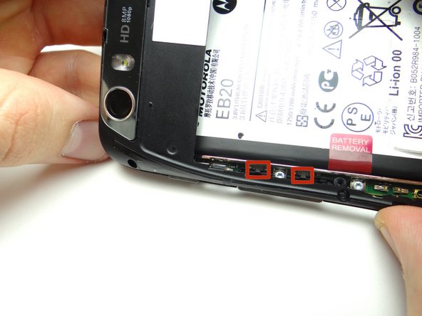
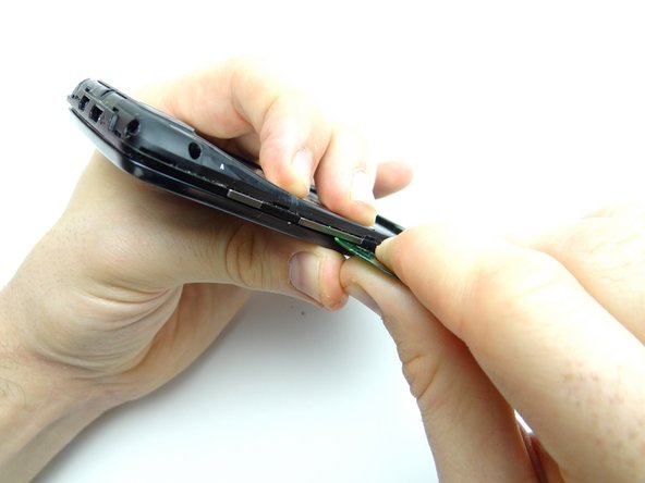
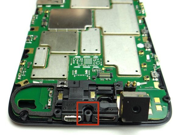
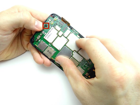
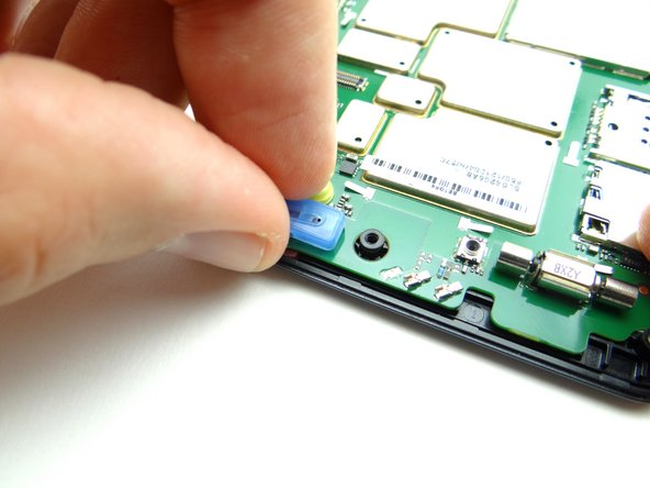
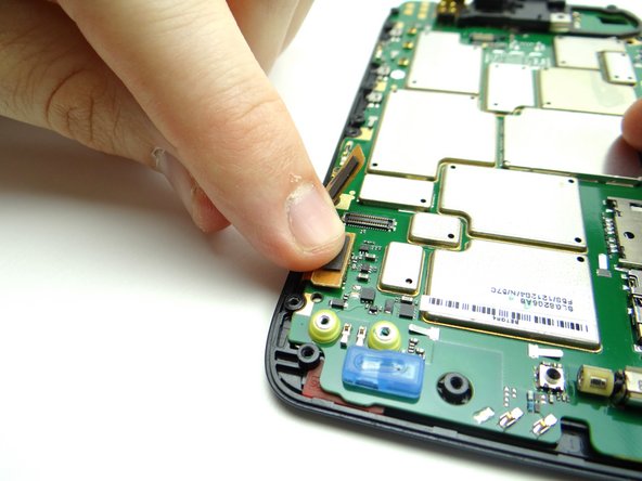
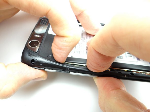
Picture 1: Be careful not to damage the volume rocker clips (red squares) while performing this step:
-
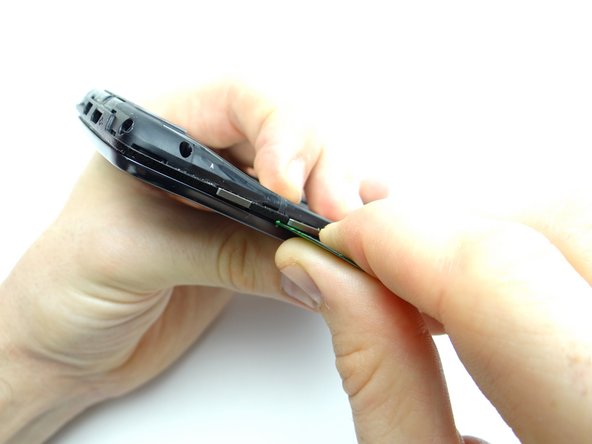
Pictures 2 & 3: Separate the mid-frame under the volume rocker with a guitar pick.
-
-
-
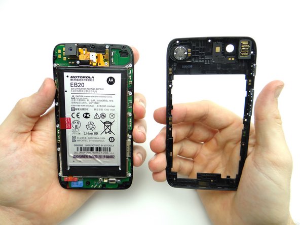
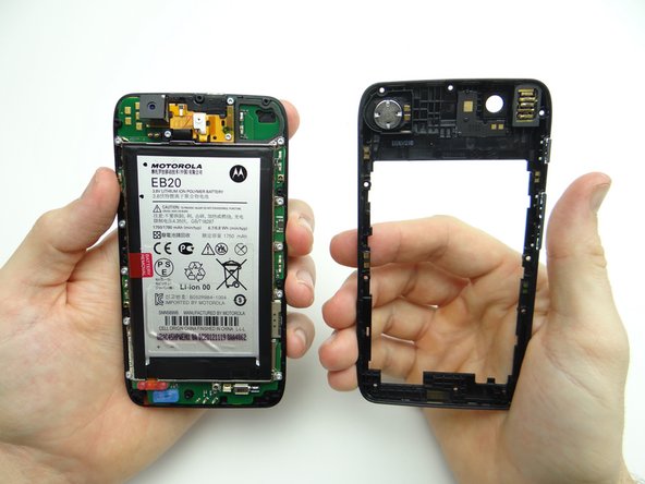
Finish peeling up the mid-frame.
-
Place either the mid-frame or front panel in Sandbox ZONE II, depending on the repair needed.
-
-
-
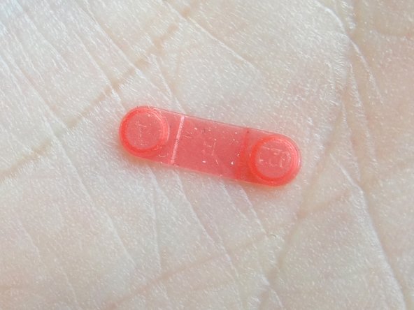
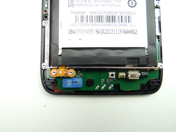
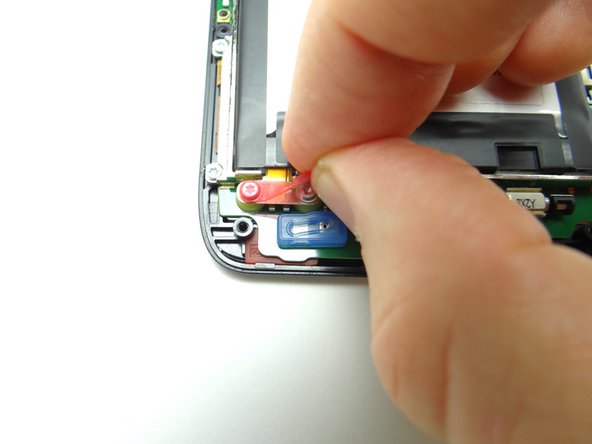
Pictures 1 & 2: Remove the pink rubber screw cover and place in SLOT 2.
-
Picture 3: Remove two 3.3mm T5 Torx screws. Place in SLOT 2 (with cover).
-
-
-
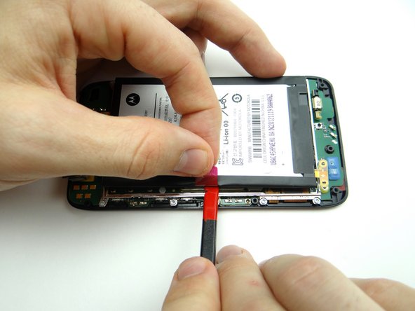
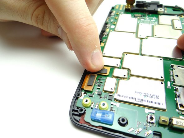
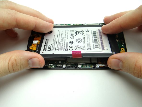
The battery is held down with mild adhesive:
-
Picture 1: Pull on battery tab to create just enough space to wedge flat end of spudger below battery.
-
Picture 2: Work your way to the bottom to release the adhesive.
-
Picture 3: Work the battery up, opening it like a book from the left edge.
-
-
-
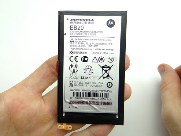
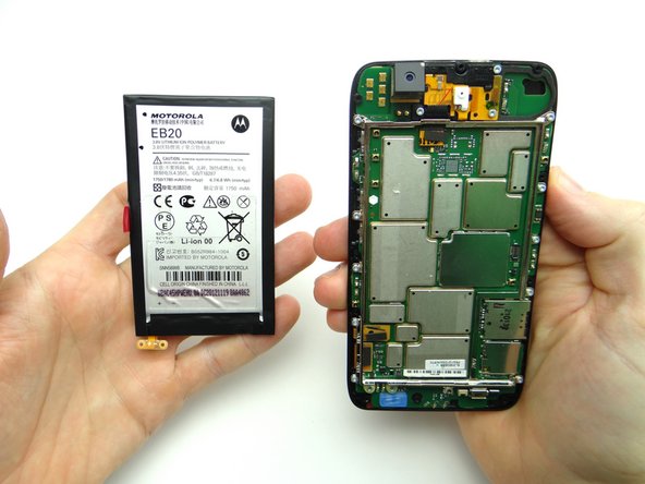
Place the battery on top of the battery cover in ZONE I.
-
-
-
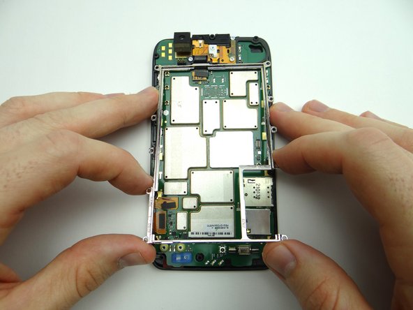
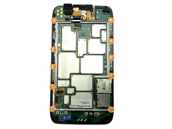
Remove ten silver 4.2mm T5 Torx screws holding down metal chassis. Place in SLOT 3.
-
Lift metal chassis away and place in ZONE III
-
-
-
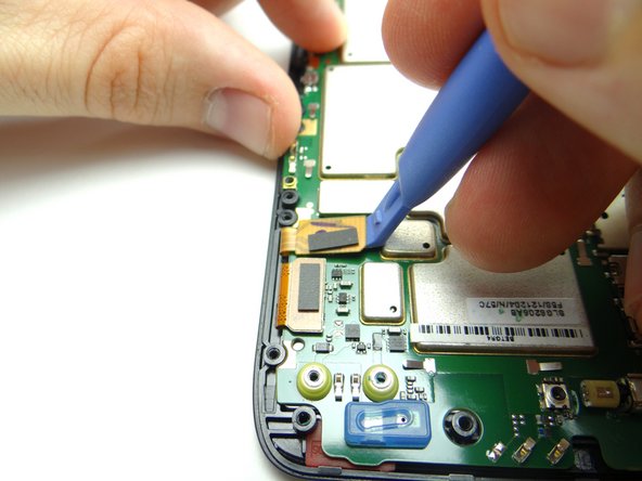
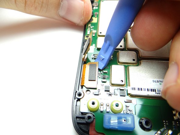
Picture 1: Use blue pry tool to disconnect digitizer cable.
-
Picture 2: Disconnect LCD cable.
-
Picture 3: Remove blue microphone cover. Place in COMPARTMENT B.
-
-
-
The LCD is held to the logic board with mild adhesive:
-
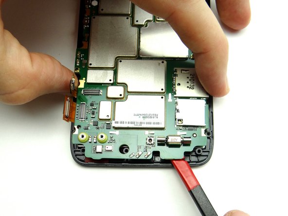
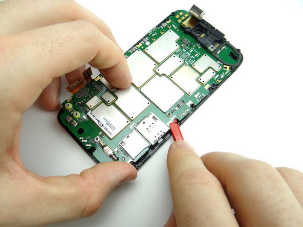
Picture 1: Insert spudger between the LCD and logic board where pictured.
-
Picture 2: Pull up logic board and LCD with your fingers while carefully separating the delicate LCD from the logic board.
-
-
-
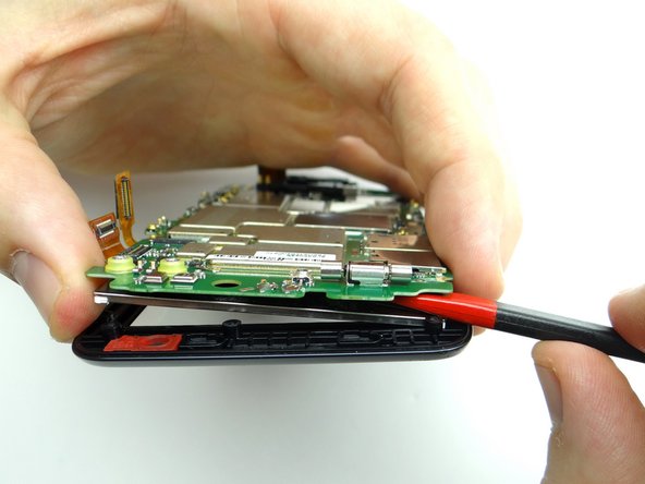
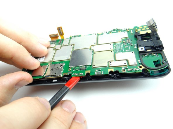
Reinsert the spudger above the SIM card tray.
-
Continue separating logic board from LCD.
-
-
-
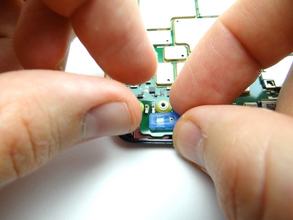
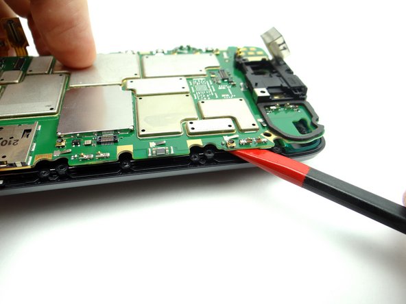
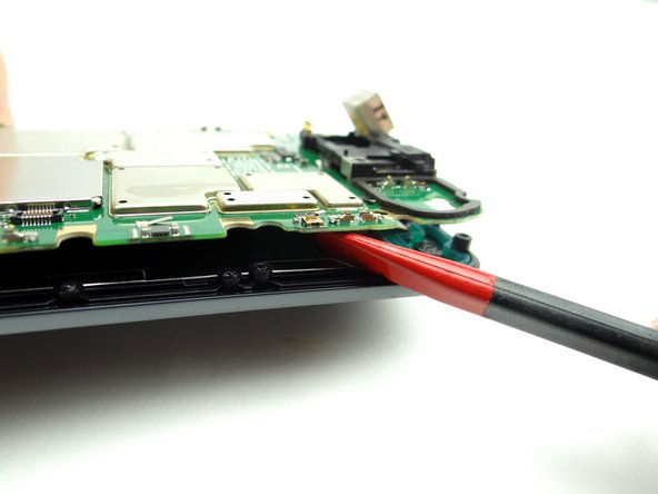
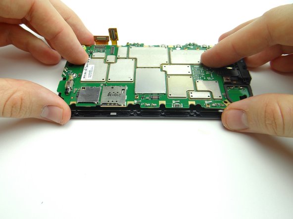
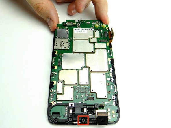
Picture 1: Insert the spudger near the top of the right side as shown.
-
Picture 2: Gently twist the spudger clockwise.
-
Picture 3: Use your fingers to pick up the side of the logic board with the SIM and SD card trays.
-
-
-
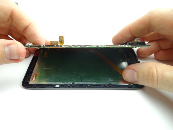
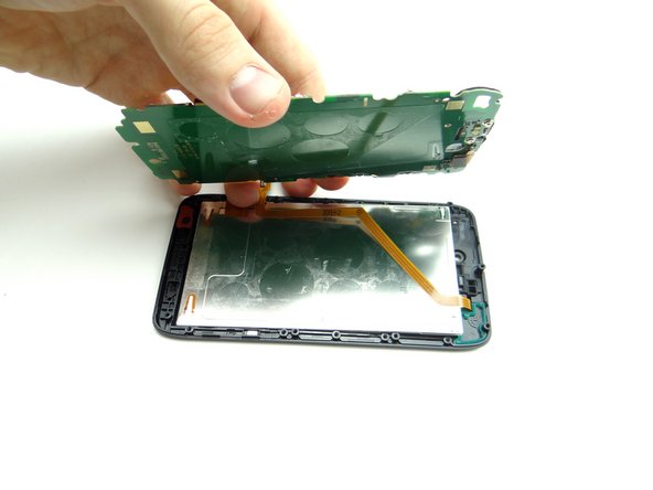
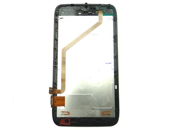
Gently separate the logic board from the display assembly.
-
Place the logic board or display assembly in ZONE IV, depending on the repair needed.
-
-
-
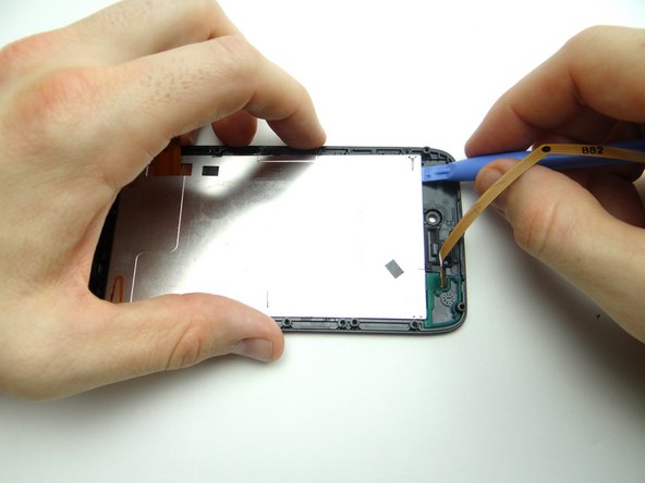
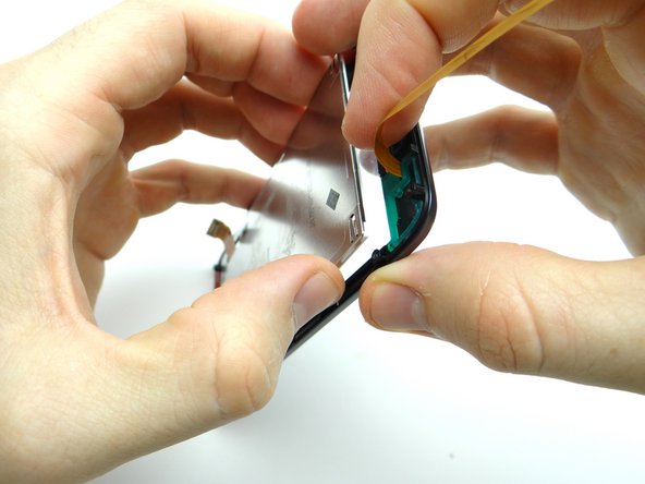
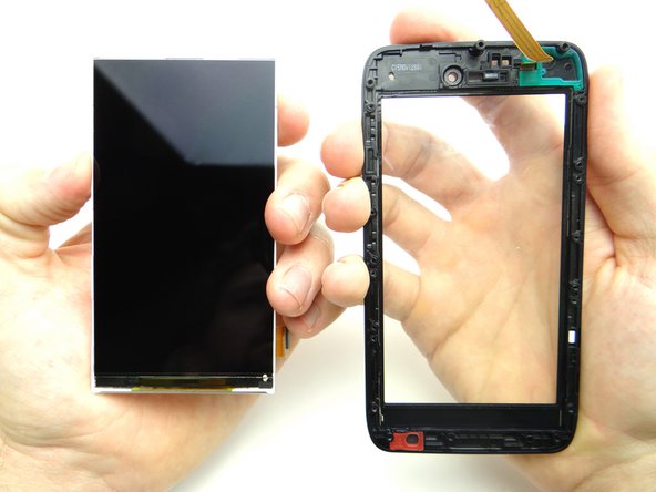
Use a blue pry tool to carefully lift the top edge of the LCD until you can grab the sides with your fingers.
-
Gently pull the LCD and digitizer glass apart.
-
-
-
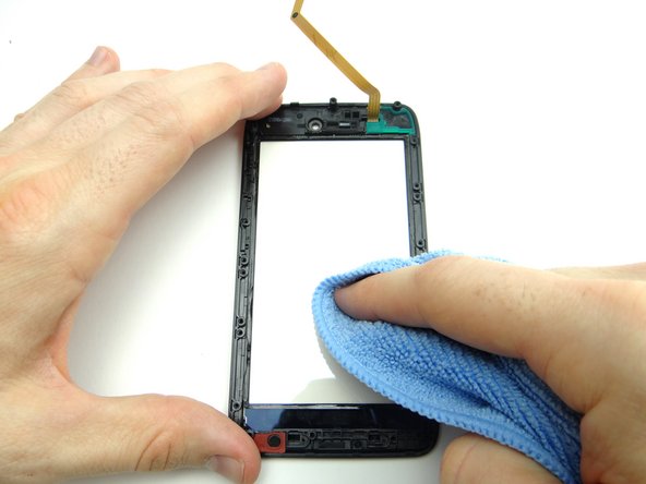
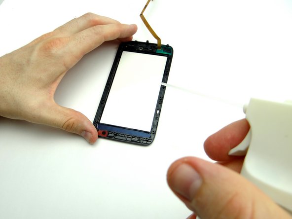
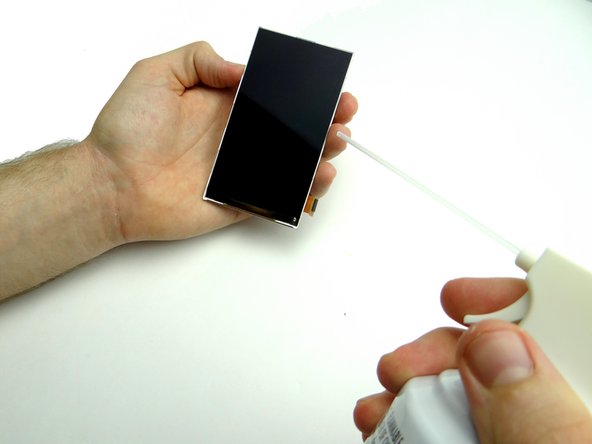
If you're reusing the digitizer, clean it with a chamois cloth and compressed air.
-
-
-
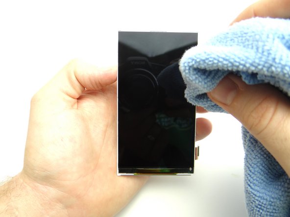
If you're reusing the LCD, clean it with a chamois cloth and compressed air.
-
-
-
Seat the LCD on the digitizer, taking care not to touch the LCD or the interior of the digitizer glass.
-
-
-
Seat the logic board on the display assembly:
-
Pictures 1 & 2: Feed the standoff at the top of the display through the notch at the top of the logic board.
-
Picture 3: Feed the standoff at the bottom of the display through the opening on the logic board. Gently push the center of the logic board into place.
-
-
-
Picture 1: Replace blue microphone cover from COMPARTMENT B.
-
Picture 2: Seat LCD cable.
-
Picture 3: Seat digitizer cable.
-
-
-
Seat metal chassis from ZONE III:
-
Replace ten silver 4.2mm T5 Torx screws holding down metal chassis from SLOT 3.
-
-
-
Replace battery from ZONE I.
-
-
-
Picture 1: Replace two 3.3mm T5 Torx screws from SLOT 2.
-
Pictures 2 & 3: Replace the pink rubber screw cover, also in SLOT 2.
-
-
-
Picture 1: Seat mid-frame on phone:
-
Pictures 2 & 3: Pivot the volume rocker on the mid-frame around the volume rocker tabs on the logic board, then snap this area of the mid-frame into place first.
-
-
-
Picture 1: Continue snapping mid-frame into place.
-
Picture 2: Check the perimeter to ensure the mid-frame is completely seated.
-
Picture 3: Replace ten 4.8mm black T5 Torx screws from SLOT 1.
-
-
-
Picture 1: From ZONE I seat battery cover, buttons side first.
-
Picture 2: Push battery cover into place.
-
Picture 3: Check around the perimeter to ensure all edges are snapped into place.
-
-
-
Replace SIM card and SD card from COMPARTMENT A.
-
Power up and test device.
-