-
-
Before disassembly, thoroughly wash and dry your hands.
-
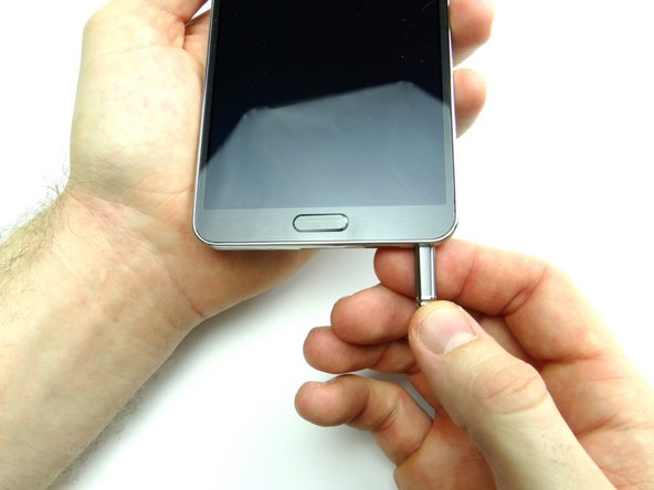
Remove the stylus, battery cover and battery. Place in ZONE I.
-
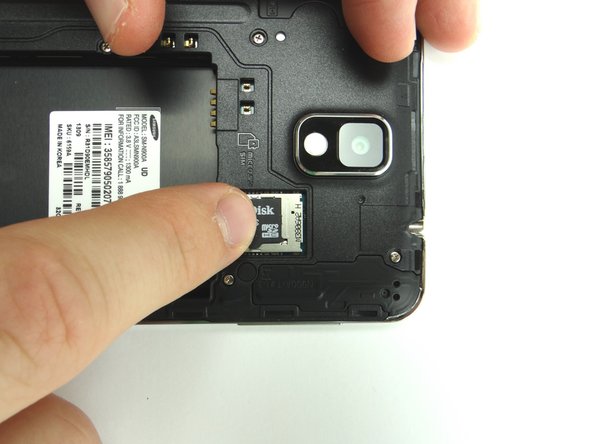
Remove SIM card and SD card. Place in COMPARTMENT A.
-
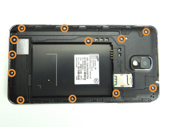
Remove twelve 4.0 mm #00 Phillips screws. Place in SLOT 1.
-
-
-
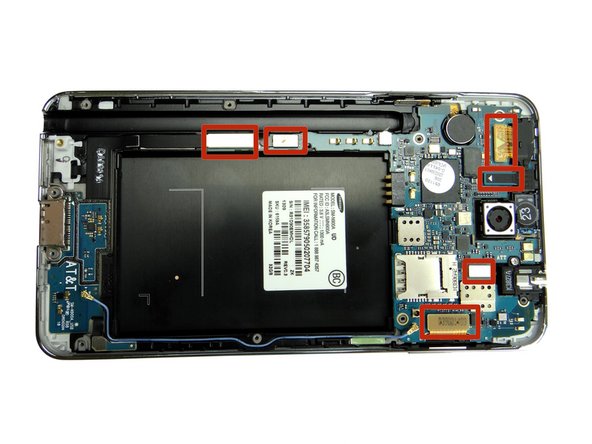
Use the Blue Pry Tool to disconnect six ribbon cable connectors on the logic board.
-
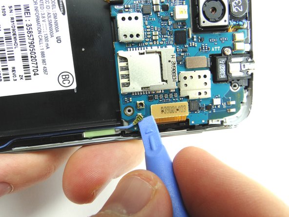
Disconnect the antenna cable using the blue pry tool as shown in Picture 2.
-
-
-
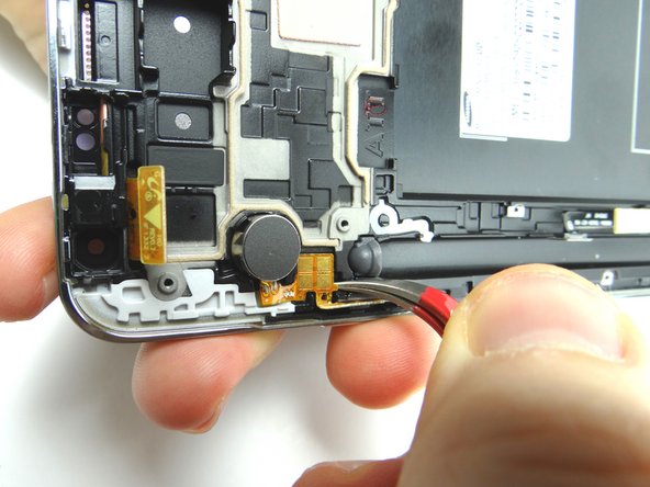
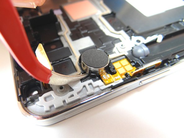
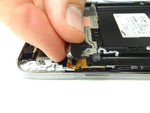
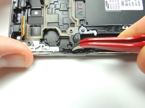
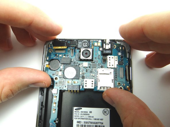
Wedge the Curved Tip Tweezers in the closed position under the contact pad connected to the vibrator and pry up to loosen it.
-
Now wedge the tweezers under the vibrator and pry up to loosen it, but don't remove it just yet.
-
-
-
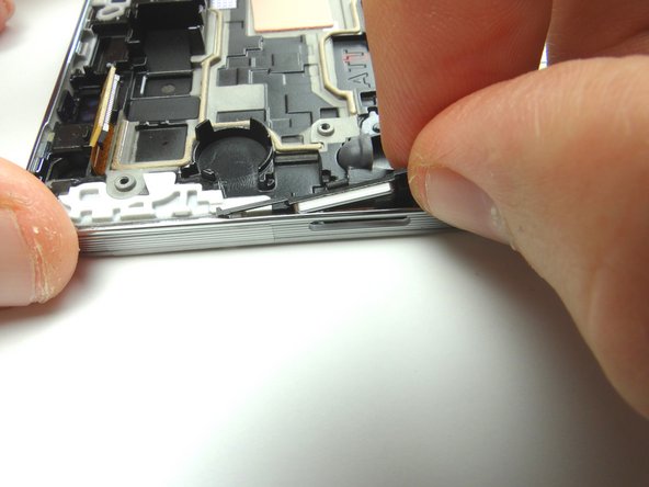
From COMPARTMENT F, replace the power button.
-
Use curved tip tweezers to press the button firmly into place.
-
-
-
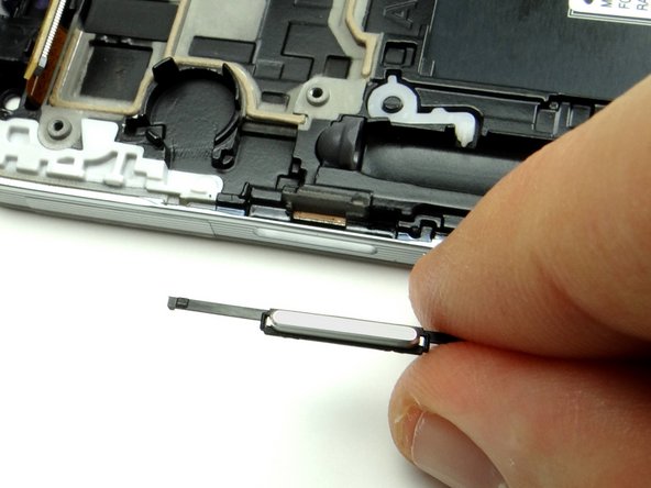
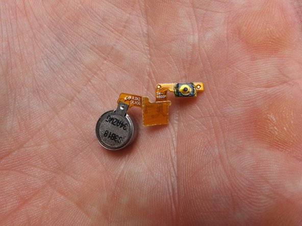
Replace the vibrator and power button cable from COMPARTMENT E.
-
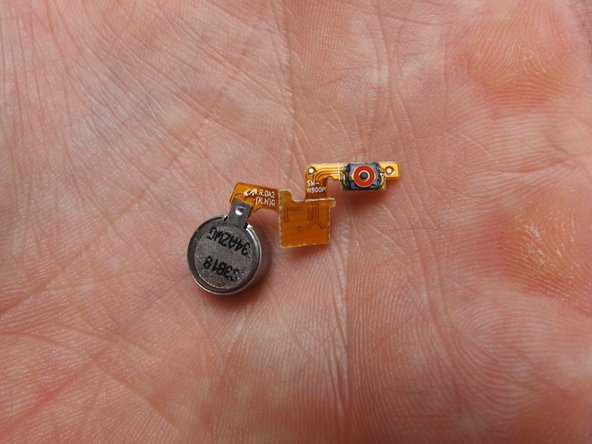
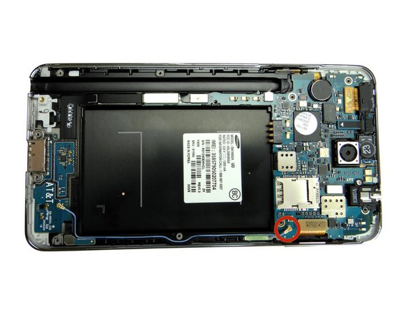
Note the small black circular power button contact circled in Picture 2. It creates the 'click' of the power button and must be properly aligned for the power button to function.
-
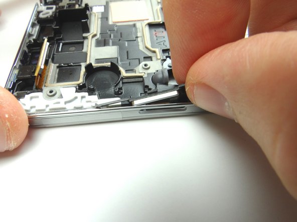
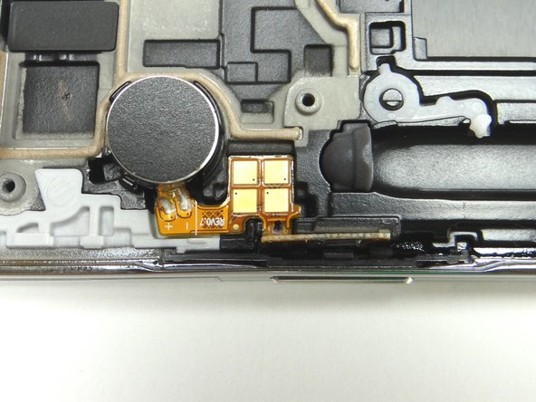
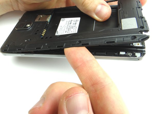
Picture 3: Shows how to place the assembly.
-
Makes sure the power button 'clicks' before continuing reassembly.
-
-
-
Replace the logic board from ZONE III. Make sure no cables are trapped underneath the logic board.
-
Reseat six cables.
-
Reseat antenna.
-
-
-
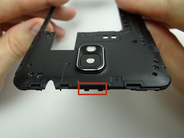
Replace mid-frame from ZONE II. Note the clips at the top of the mid-frame.
-
Place the mid-frame clips in their slots at the top of the front panel before seating the rest of the mid-frame.
-