Parts
No parts specified.
-
-
Before disassembling the Samsung Galaxy S4, thoroughly wash and dry your hands.
-
Picture 1: Remove the battery cover using the notch at the upper left-hand corner. Remove the battery too and place both into ZONE I.
-
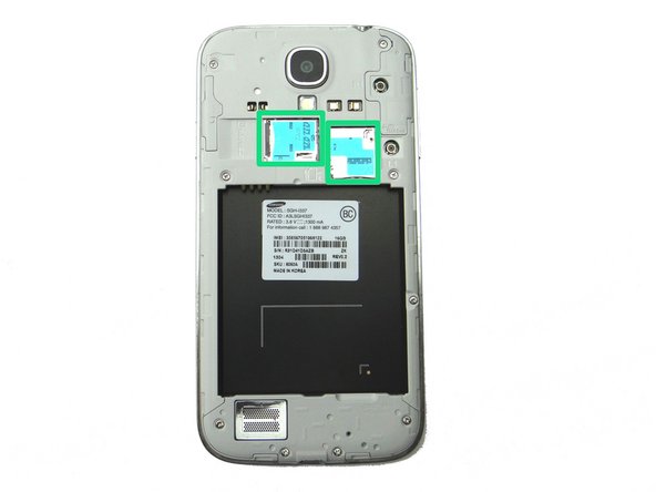
Picture 2: Remove SIM card and SD card. Place in COMPARTMENT A.
-
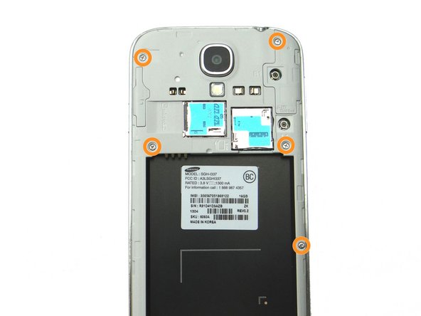
Picture 3: Remove four 4.0 mm Phillips screws. Place in SLOT 1.
-
-
-
Picture 1: Remove five 4.0 mm Phillips screws. Place in SLOT 1.
-
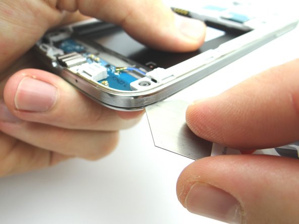
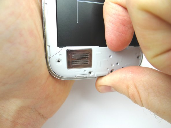
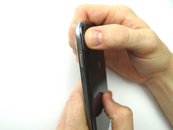
Picture 2: Use the iSesamo to create enough separation between the mid-frame and the front panel assembly to wedge a Blue Pry Tool between the two.
-
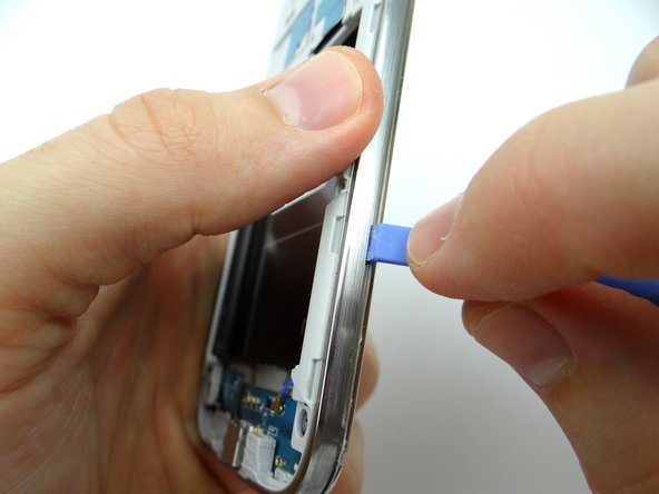
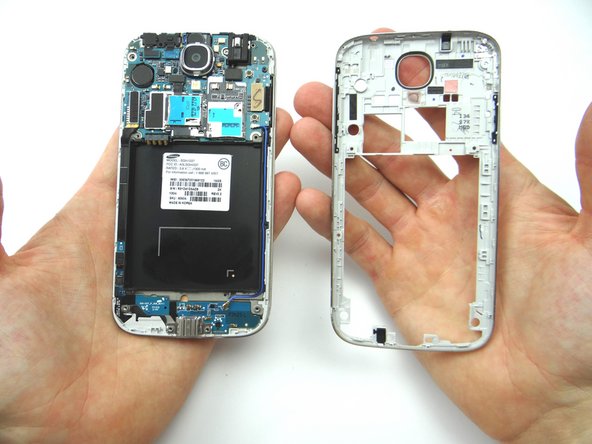
Picture 3: After you create enough separation, wedge the Blue Pry Tool between mid-frame and front panel. Move the Blue Pry Tool up the right side and around each edge of the phone, popping the clips holding the mid-frame to the front panel along the way.
-
Place mid-frame into ZONE II.
-
-
-
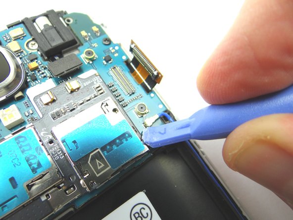
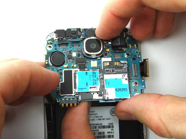
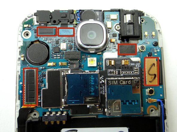
Picture 1: Using the Blue Pry Tool, disconnect five cable connectors on the logic board.
-
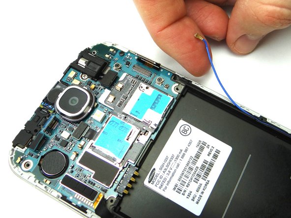
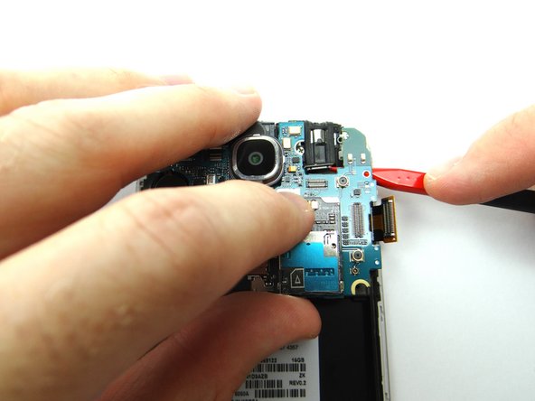
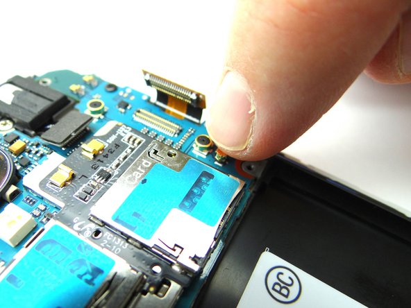
Picture 2: Disconnect the antenna cable.
-
-
-
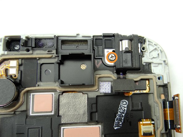
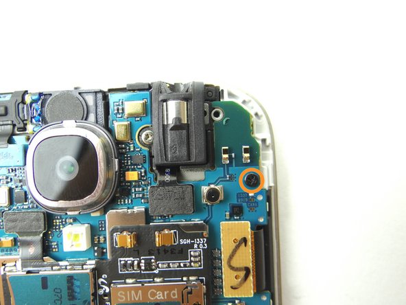
Remove one 2.2 mm Phillips screw and place into SLOT 5.
-
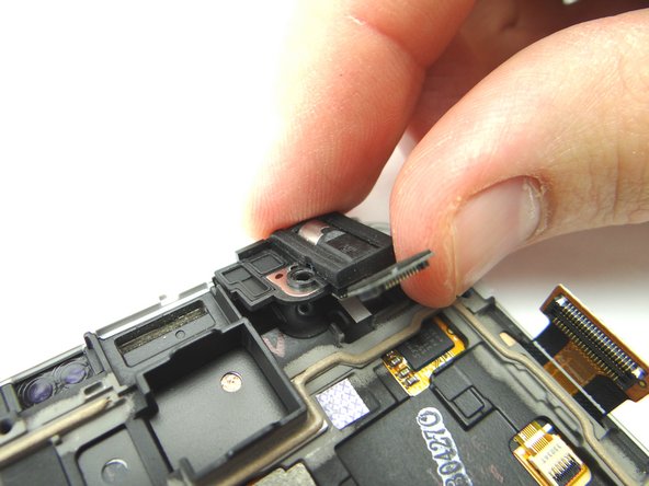
Use your fingers to remove the headphone jack and place into COMPARTMENT F.
-
-
-
Replace the headphone jack from COMPARTMENT F.
-
Replace one 2.2 mm Phillips screw from SLOT 5.
-
-
-
Picture 1: Replace the logic board from ZONE III.
-
Picture 2: You may have to use the Black Spudger to feed the headset jack cable through to the top of the logic board.
-
Picture 3: Replace one 2.4 mm Phillips screw from SLOT 2.
-
-
-
Replace the mid-frame from ZONE II.
-
Secure the mid-frame with five 4.0 mm Phillips screws from SLOT 1.
-
-
-
Picture 1: Replace the loudspeaker from Compartment B.
-
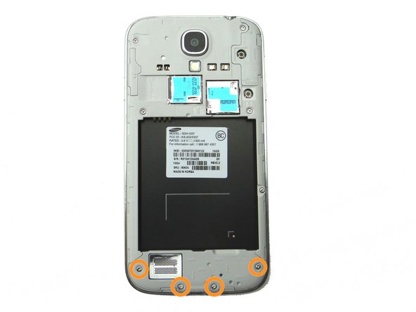
Picture 2: Replace four 4.0 mm Phillips screws from SLOT 1.
-
Picture 3: Replace SIM card and SD card from COMPARTMENT A.
-