Introduction
Outline what you are going to teach someone how to do.
-
-
Power down the device.
-
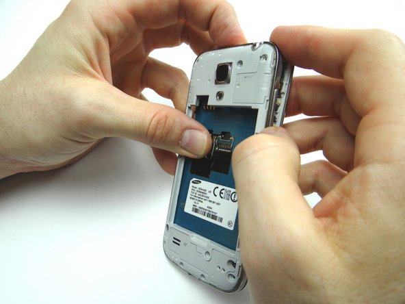
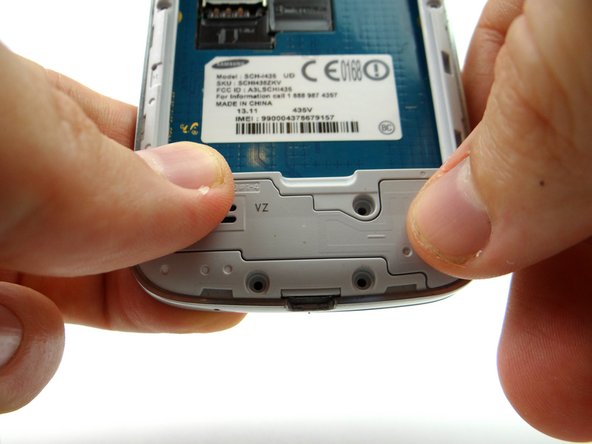
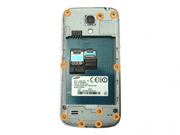
Remove battery cover and battery. Place in ZONE I.
-
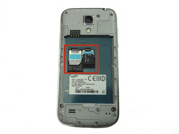
Remove SIM card and SD card. Place in COMPARTMENT A.
-
-
-
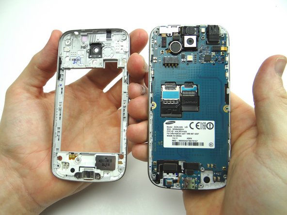
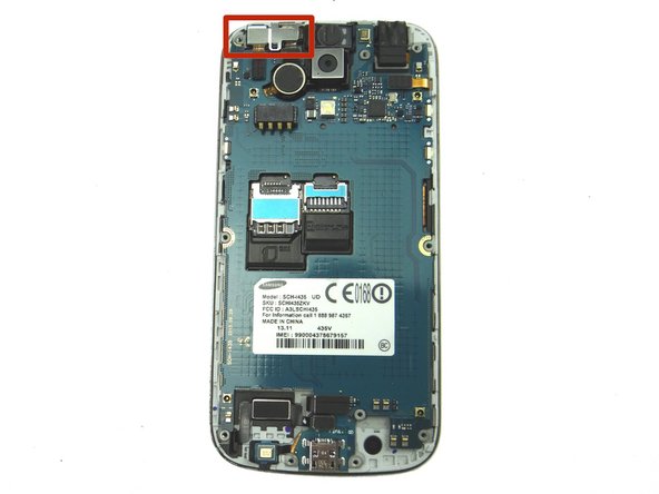
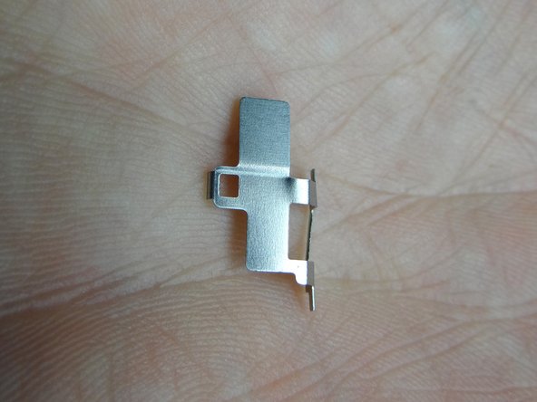
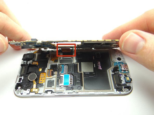
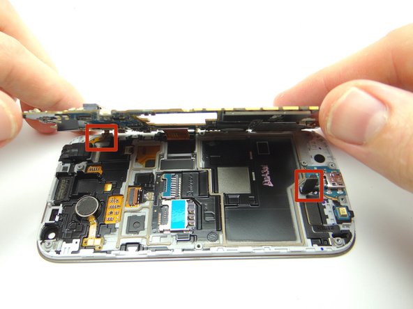
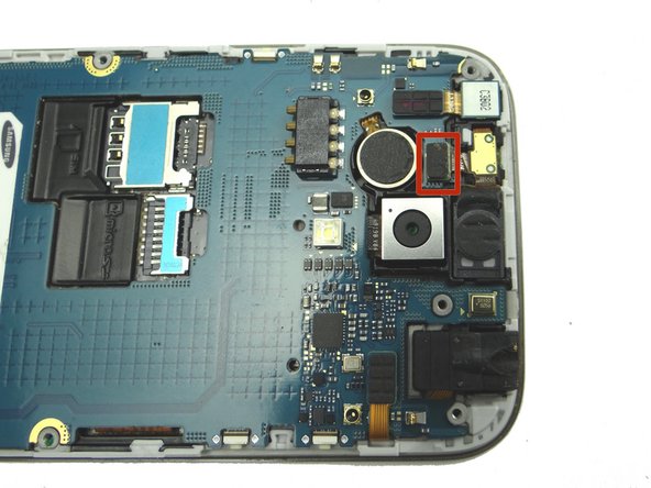
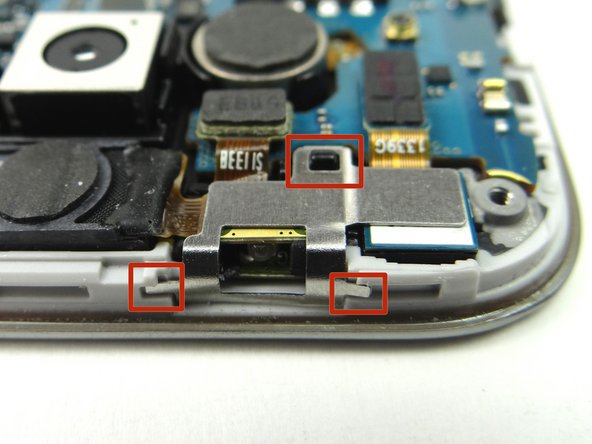
Remove metal shield:
-
Use curved-tip tweezers to grab metal shield and work it around the tabs creating tension (marked in Picture 2).
-
-
-
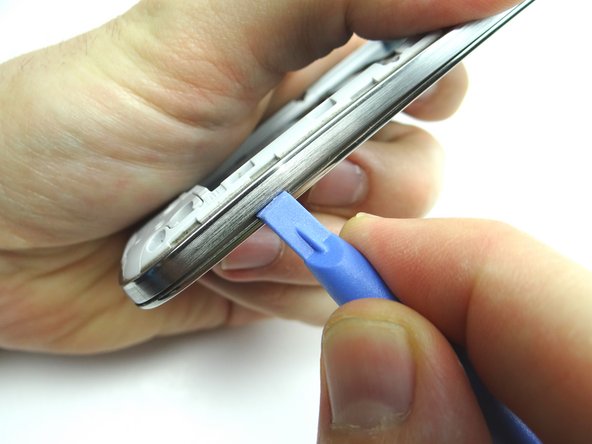
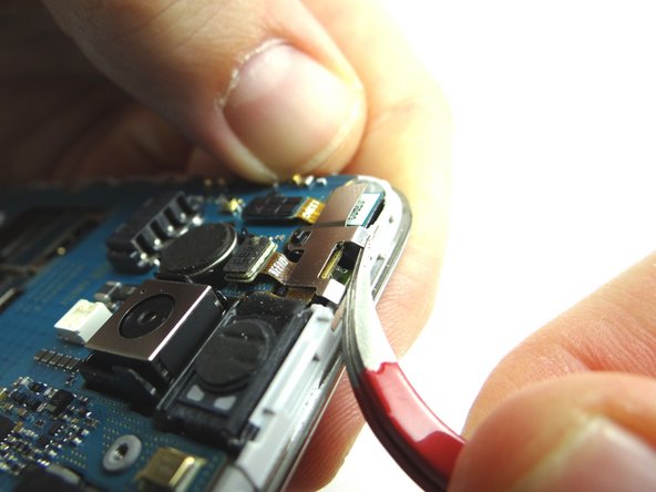
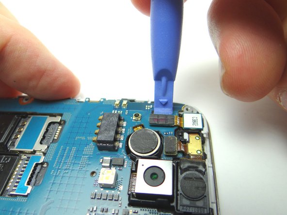
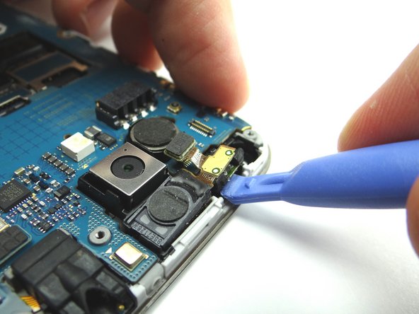
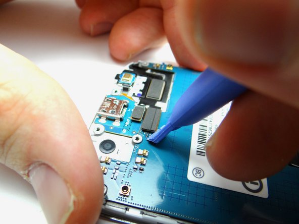
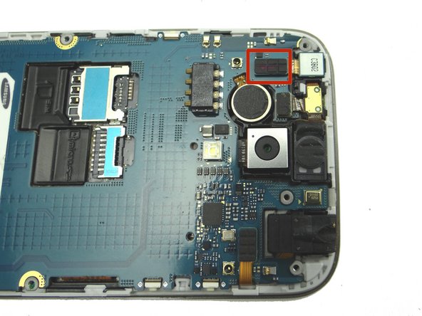
Picture 1: Use blue pry tool to disconnect earpiece speaker / proximity sensor cable.
-
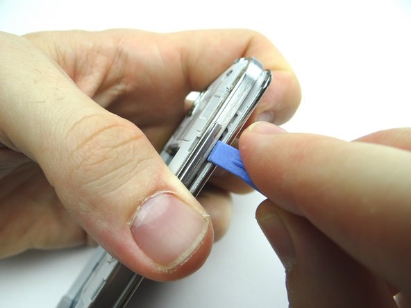
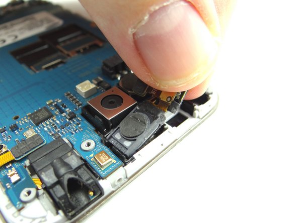
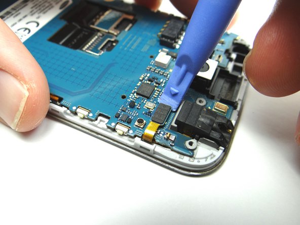
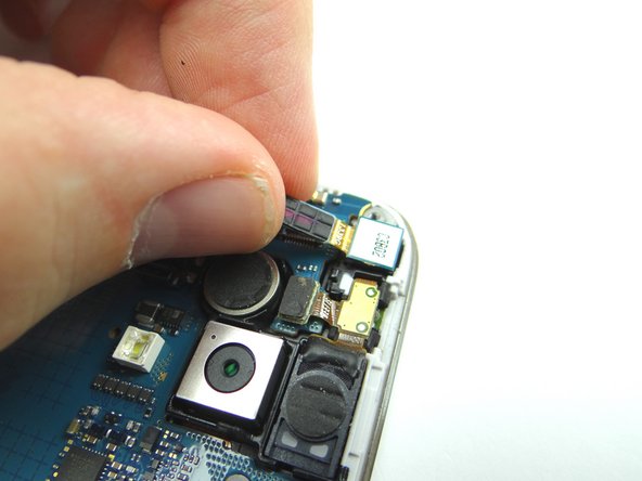
Picture 2: Use blue pry tool to lift proximity sensor up enough to grab with your fingers.
-
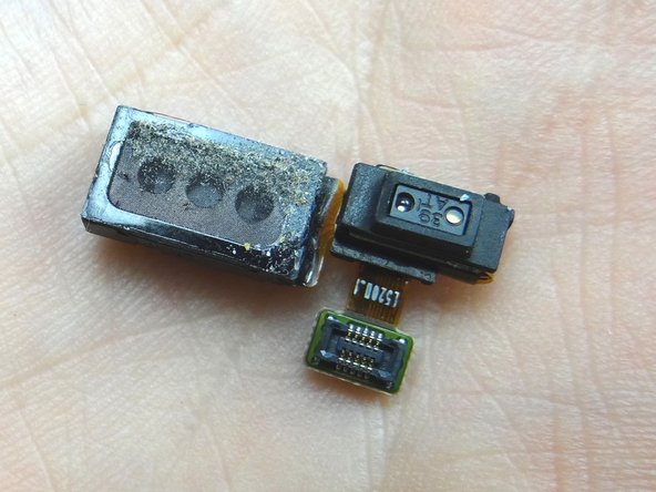
Picture 3: Peel up earpiece speaker / proximity sensor assembly.
-
-
-
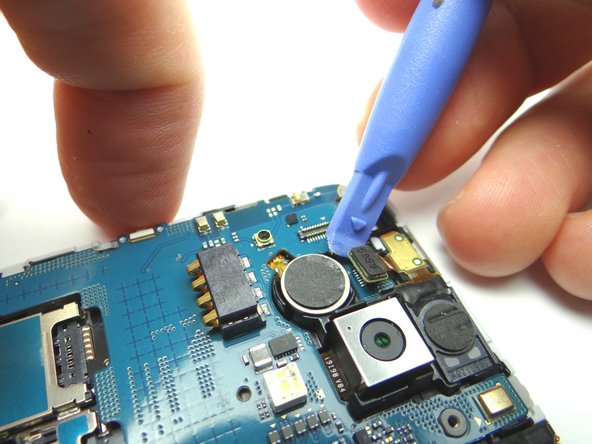
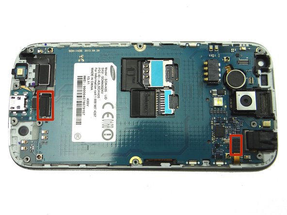
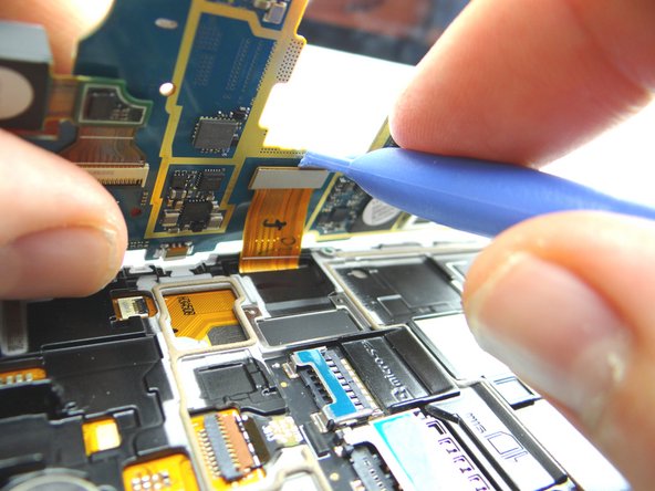
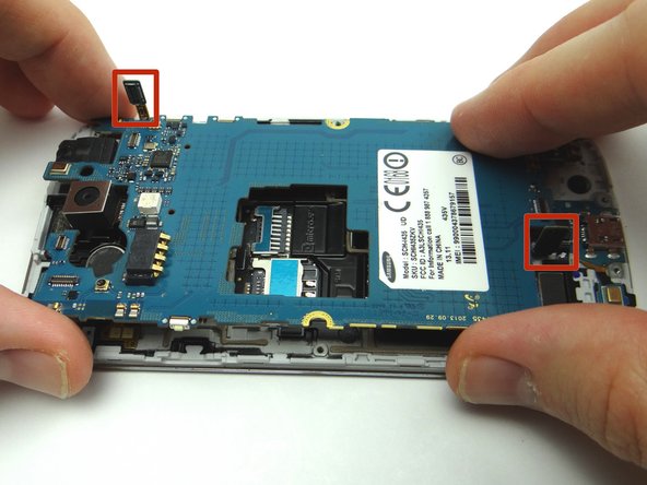
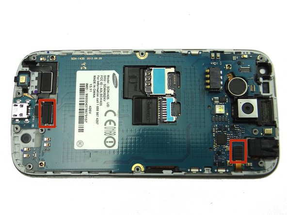
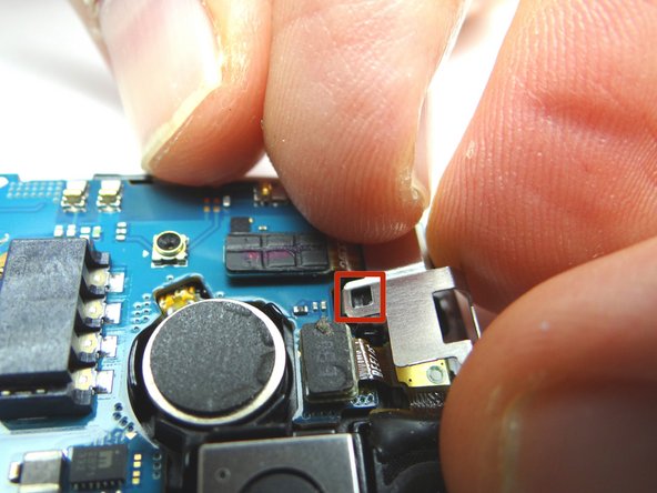
Picture 1: Disconnect the pictured cables:
-
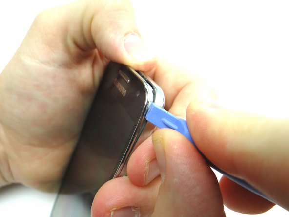
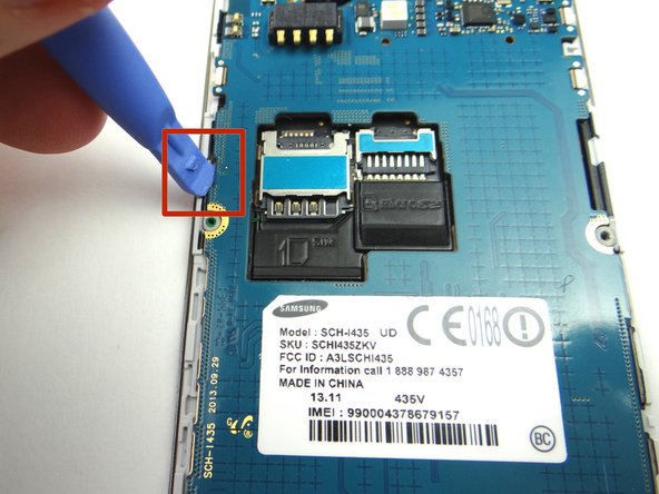
Picture 2: Use the blue pry tool to disconnect charging port cable.
-
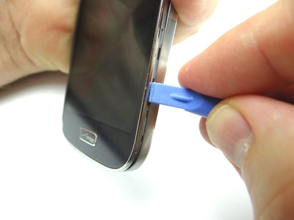
Picture 3: Disconnect headphone jack cable.
-
-
-
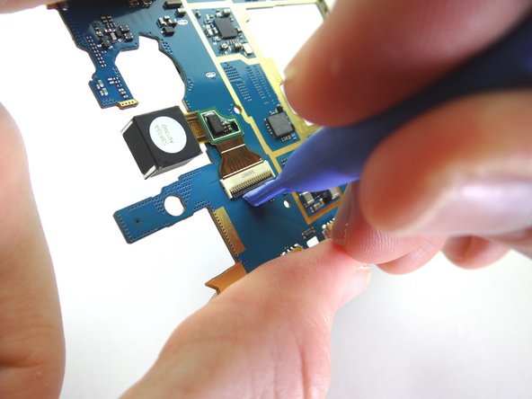
On underside of logic board:
-
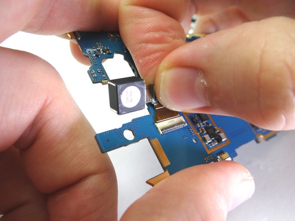
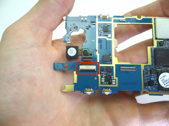
Open rear camera ZIF connector with blue pry tool.
-
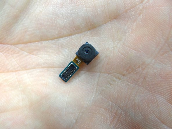
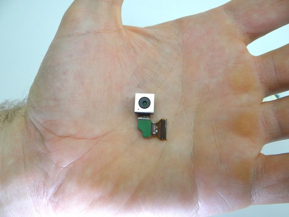
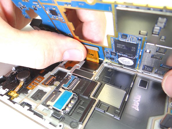
Pull rear camera free.
-
Place in COMPARTMENT D.
-
-
-
From COMPARTMENT D:
-
Connect rear camera to ZIF connector on underside of logic board.
-
Close ZIF connector.
-
-
-
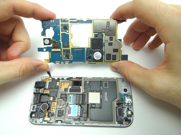
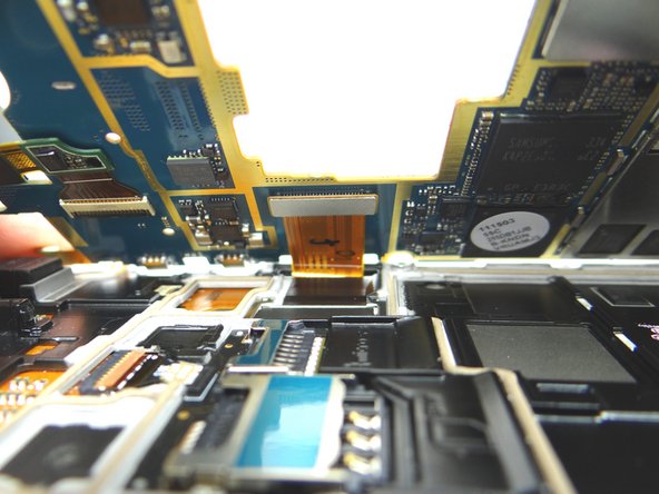
Bring logic board and front panel together at a 45° angle. Push display cable firmly into place.
-
-
-
From COMPARTMENT C, use your fingers to seat earpiece speaker / proximity sensor.
-
Connect the cable.
-
-
-
From COMPARTMENT C, seat front-facing camera with your fingers.
-
Connect the cable.
-
-
-
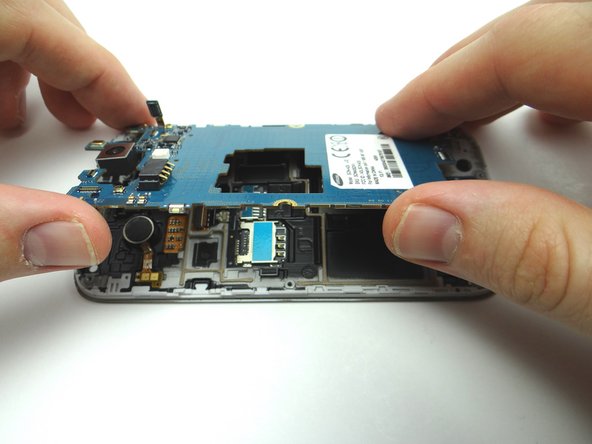
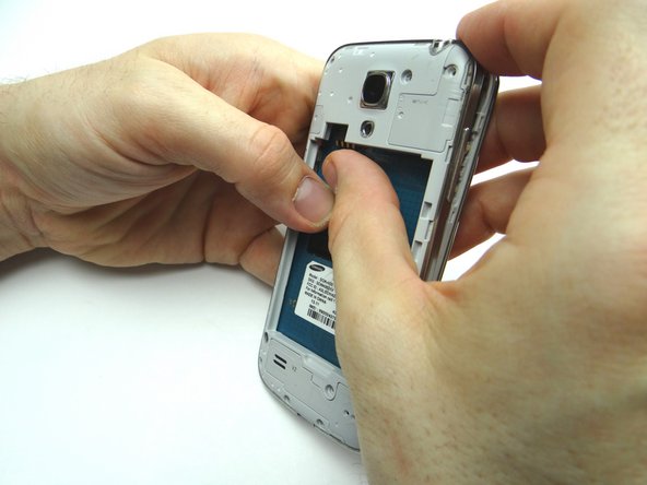
Picture 1: Line up mid-frame with front panel. Seat bottom near charging port first.
-
Picture 2: Work your way to the top.
-
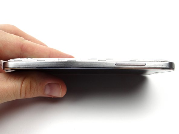
Picture 3: Check the perimeter to make sure all edges are snapped into place.
-