-
-
Before disassembly, thoroughly wash and dry your hands. Power down the device.
-
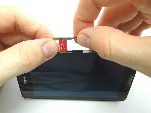
Find the opening in the SIM card tray roughly an inch above the charging port. Gently push a small paper clip into the opening to 'pop up' the SIM card tray.
-
Remove the tray, SIM card and SD card. Place all three in COMPARTMENT A.
-
-
-
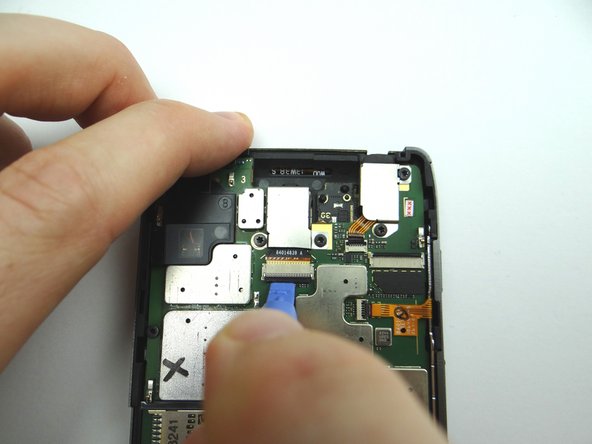
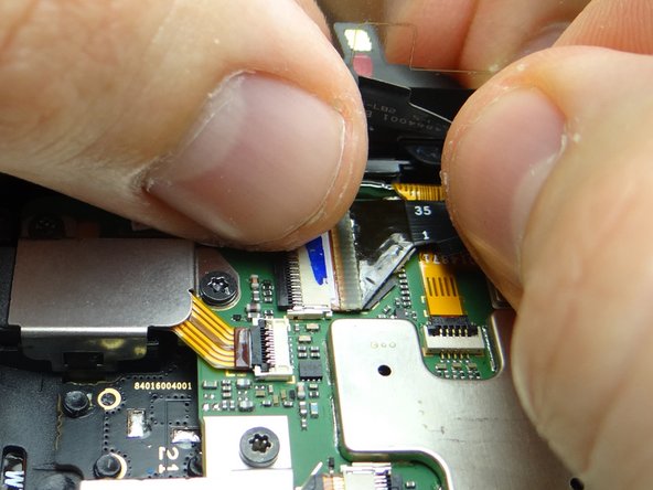
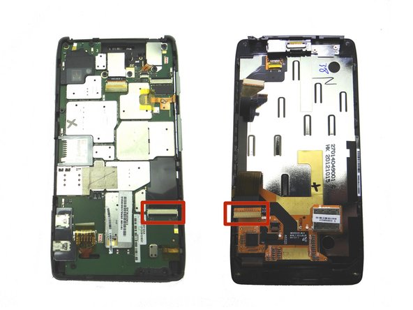
The display cable connector is two inches down from the component connector:
-
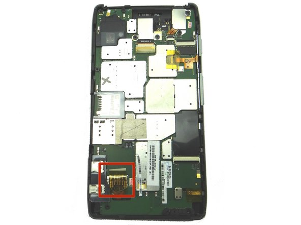
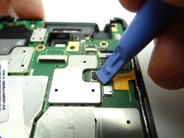
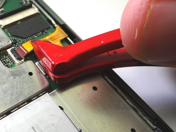
Picture 1: Peel up yellow Kapton tape with plastic tweezers. Adhere the tape to the wall of COMPARTMENT E. (You'll need a piece of Kapton tape for reassembly to help hold the display cable in place.)
-
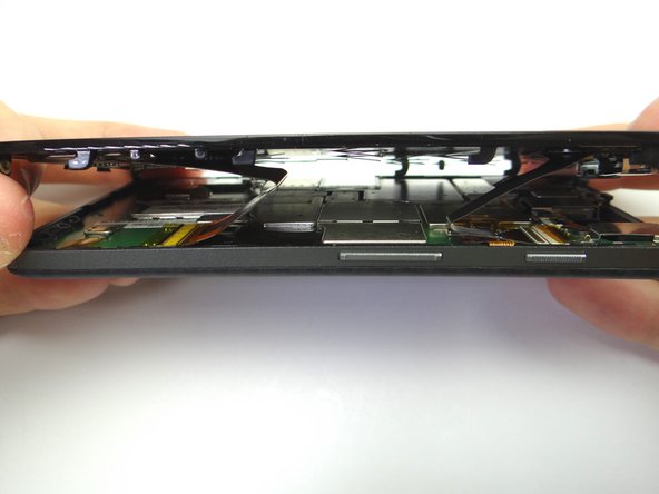
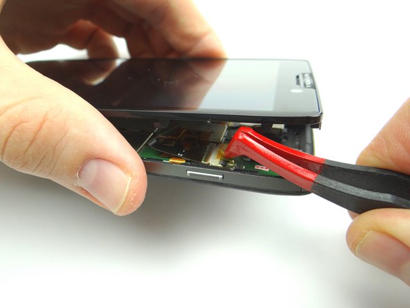
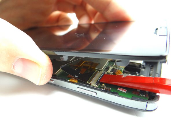
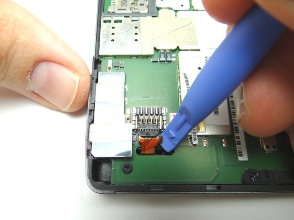
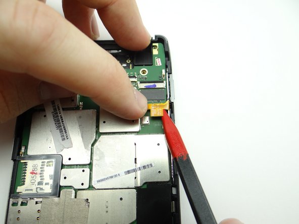
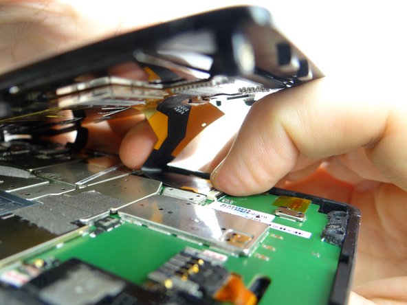
Picture 2: Use flat end of spudger to push the black ZIF connector open.
-
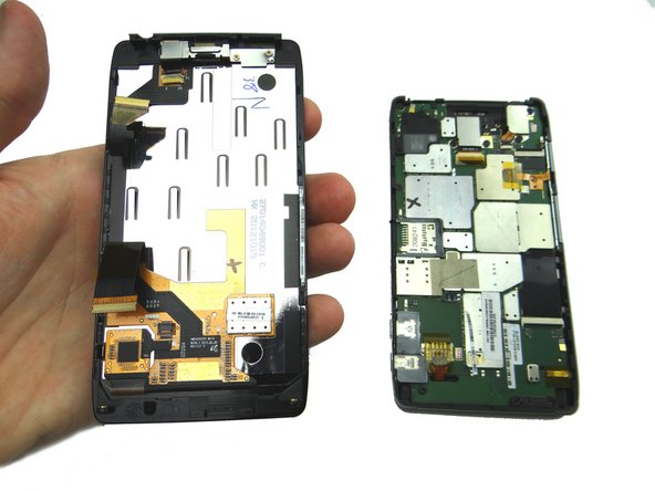
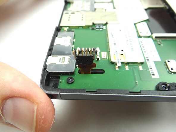
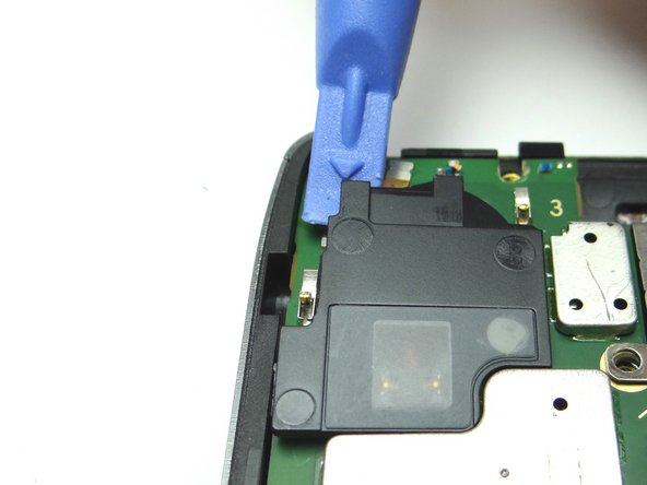
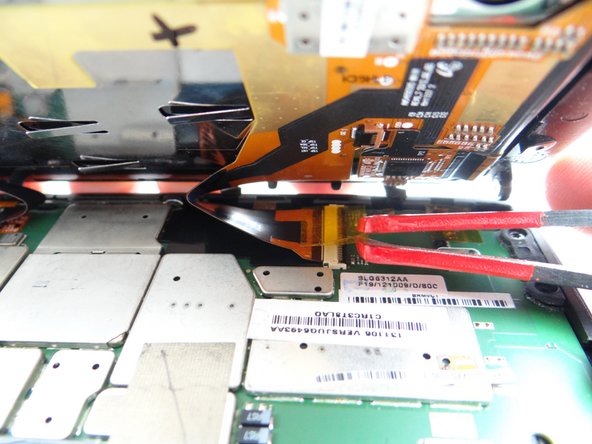
Picture 3: Gently guide the display cable out of the ZIF connector.
-
-
-
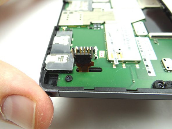
Remove Kapton tape covering battery connector.
-
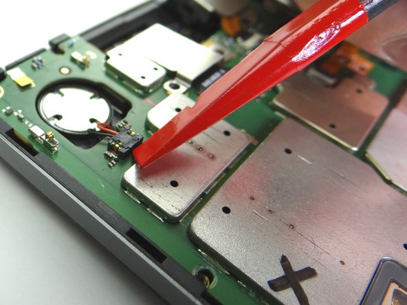
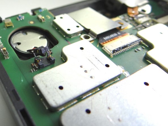
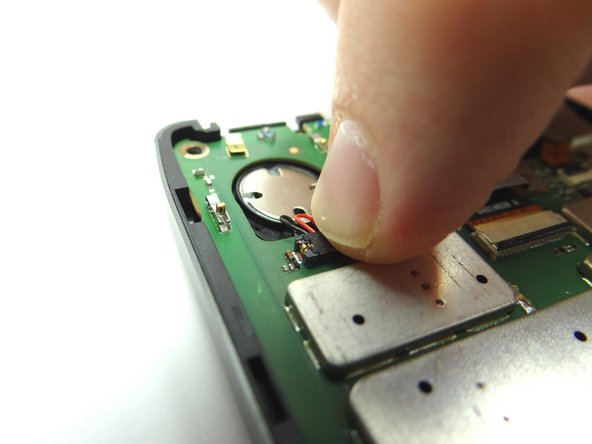
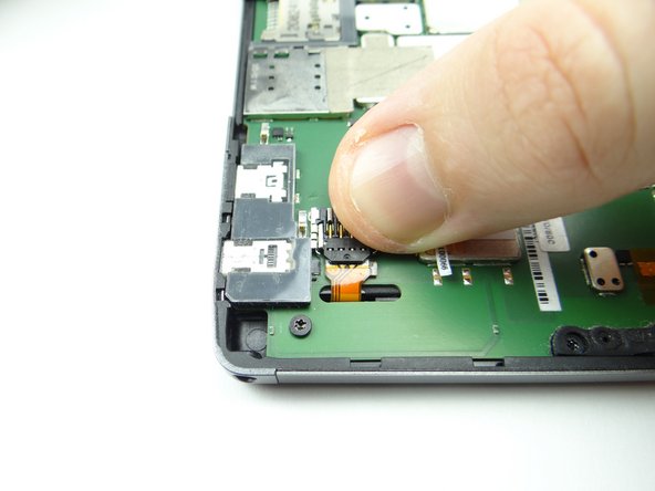
Lift the battery connector into the upright position.
-
This should take very little force.
-
-
-
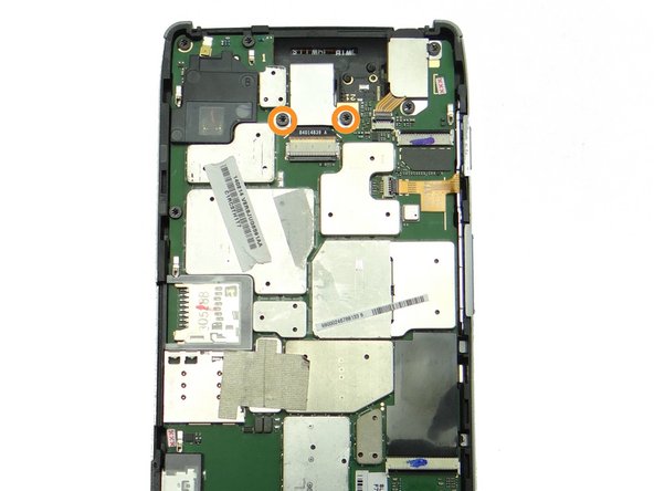
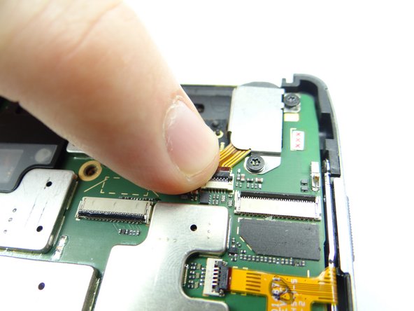
Picture 1: Use plastic tweezers to remove Kapton tape covering rear camera ZIF connector.
-
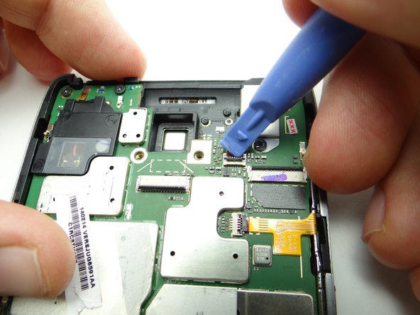
Picture 2: Use blue pry tool to open ZIF connector.
-
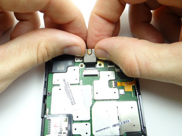
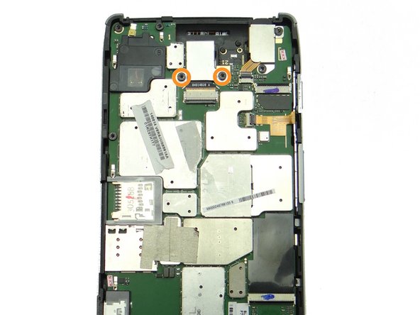
Remove two 3.6 mm T5 Torx screws. Place in SLOT 2.
-
-
-
Picture 1: Use blue pry tool to open headphone jack ZIF connector.
-
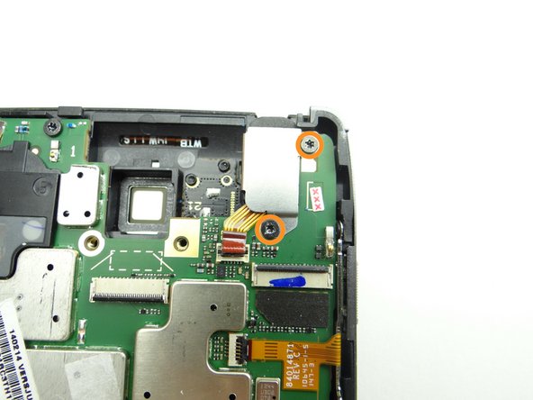
Picture 2: Remove two 3.6 mm T5 Torx screws. Place in SLOT 2.
-
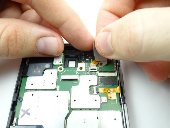
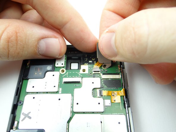
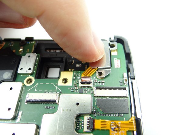
Picture 3: The headphone jack cable is attached to the headphone jack cover. Lift the cover while guiding the cable out of the ZIF connector.
-
-
-
Picture 1: Open the buttons cable ZIF connector.
-
Picture 2: Use your left hand to push the cable out of the connector while gently tugging the cable with the pointed end of the spudger in your right hand.
-
Picture 3: Fold the cable back slightly to make sure it's out of the way when lifting up the logic board.
-
-
-
Picture 1: Remove six 3.6 mm T5 Torx screws from logic board. Place in SLOT 2.
-
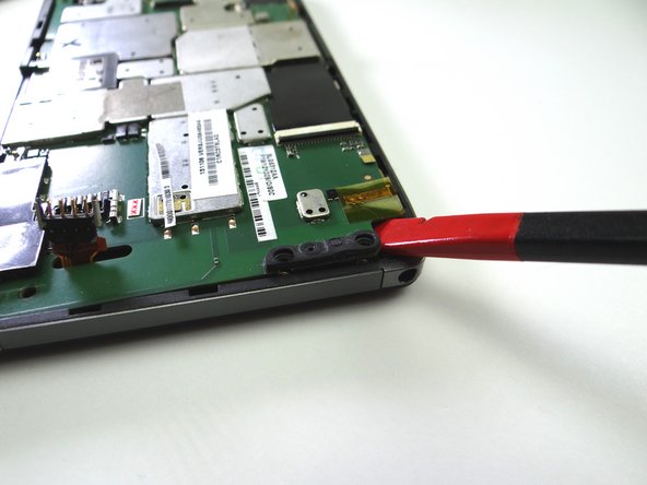
Picture 2: Use the flat end of the spudger to pry up the lower-left corner of the logic board.
-
Picture 3: With the corner up, grab the logic board with both hands and continue lifting carefully. Make sure the speaker, buttons and battery cables don't get caught as you continue removing the logic board.
-
Place logic board in ZONE III.
-
-
-
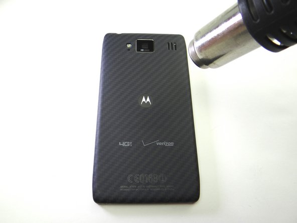
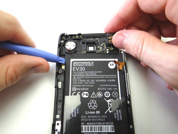
Picture 1: Apply low-level 100° Celsius heat to the battery cover to loosen the adhesive holding the battery in place.
-
Picture 2: Start lifting the battery in the upper-left corner with blue pry tool. Work your way down the left side.
-
If you're repairing an HD MAXX you may have to use a spudger to push through the adhesive on the underside of the battery.
-
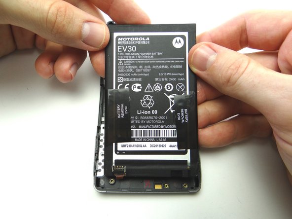
Picture 3: Finish removing battery with your fingers. Take care not to warp it. Place in ZONE IV.
-
-
-
Replace logic board from ZONE III:
-
Make sure to feed the speaker, buttons and battery cables through as you're seating the logic board.
-
Replace six 3.6 mm T5 Torx screws on logic board from SLOT 2.
-
-
-
From COMPARTMENT D, replace headphone jack cover: guide cable into ZIF connector while seating cover.
-
-
-
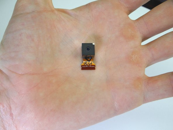
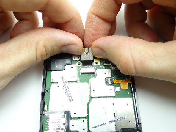
Picture 1: From COMPARTMENT D, replace rear camera:
-
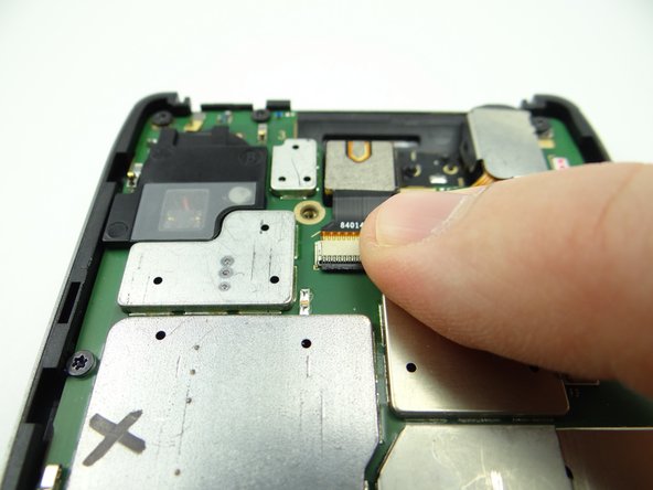
Picture 2: Guide cable into ZIF connector while seating the camera.
-
Picture 3: Close ZIF connector.
-
-
-
Connect component cable:
-
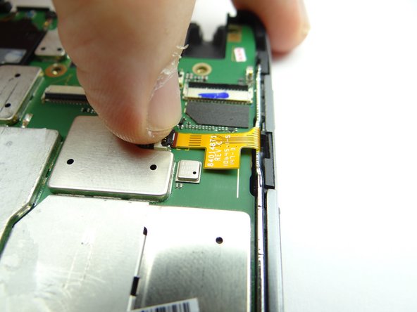
Guide component cable into open ZIF connector. Hold component cable in place with one hand, while closing ZIF connector with your thumb on opposite hand.
-
-
-
Picture 1: Connect display cable:
-
Picture 2: Guide display cable into open ZIF connector. Hold display cable in place with one hand, while closing ZIF connector with your thumb on opposite hand.
-
Picture 3: Cover the display cable connector with Kapton tape from COMPARTMENT E.
-
The display cable has a tendency to come loose when closing the front panel on the rear panel. It's important to replace the yellow Kapton tape to ensure the cable is held in place.
-
Almost done!
Finish Line


