-
-
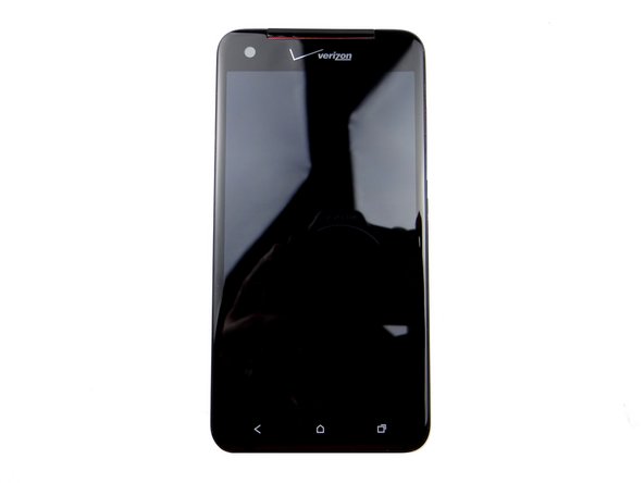
Power down device.
-
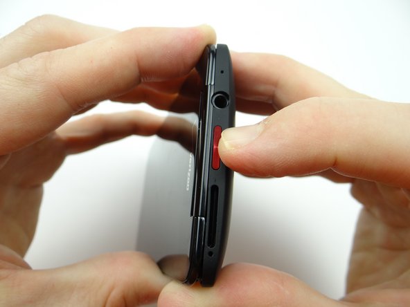
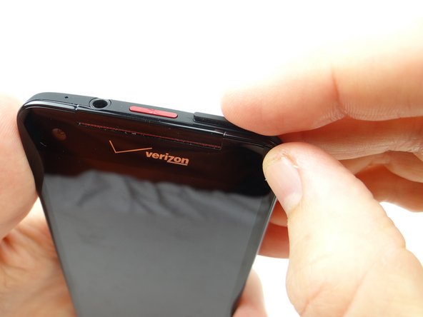
Push down on SIM card ejector slot with a paper clip to pop up the tray.
-
Finish removing the SIM card tray with your fingers. Place SIM card and tray in COMPARTMENT A.
-
-
-
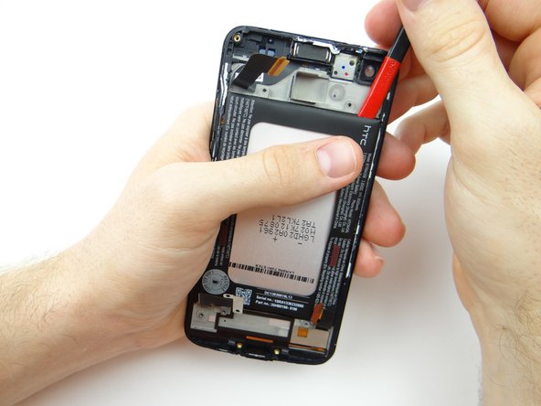
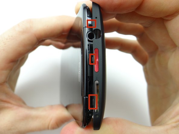
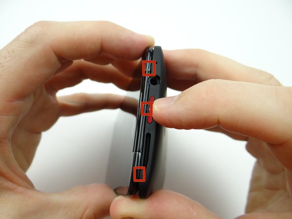
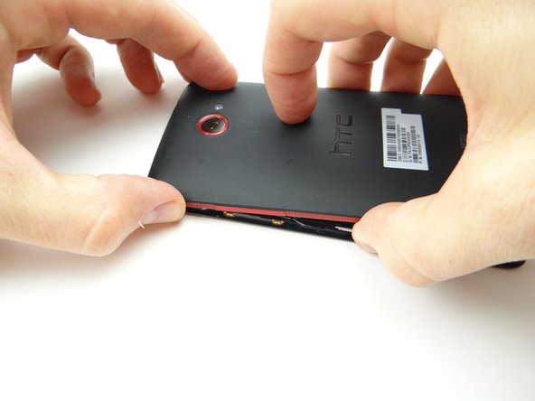
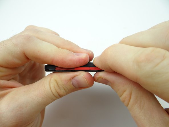
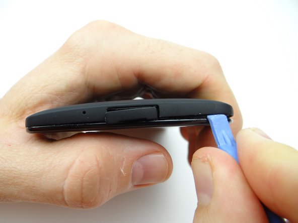
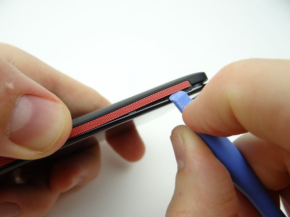
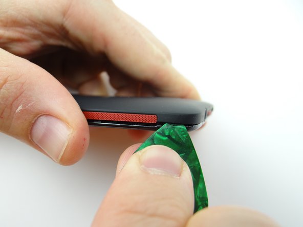
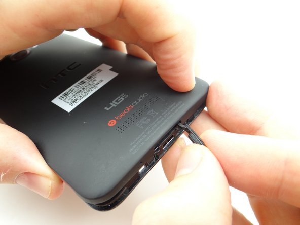
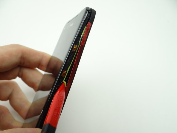
Picture 1: Sweep along the bottom edge from left to right releasing clips holding the battery cover down.
-
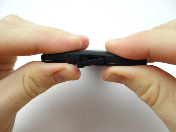
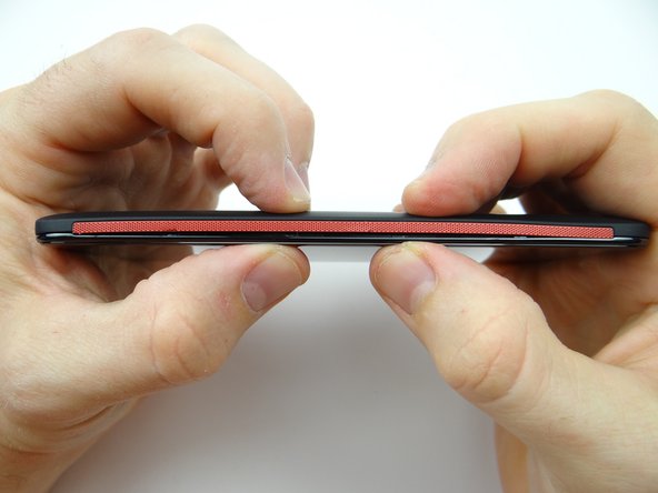
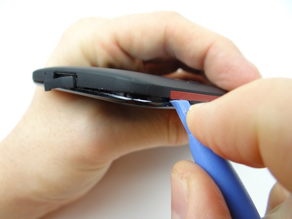
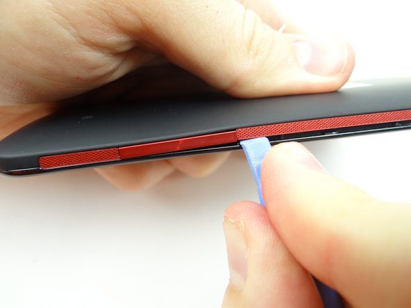
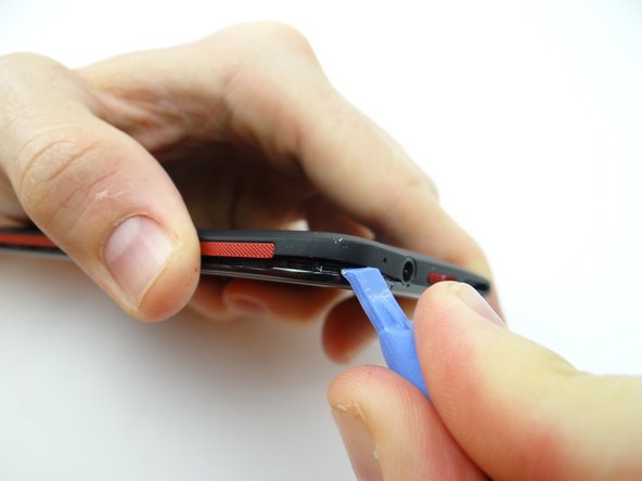
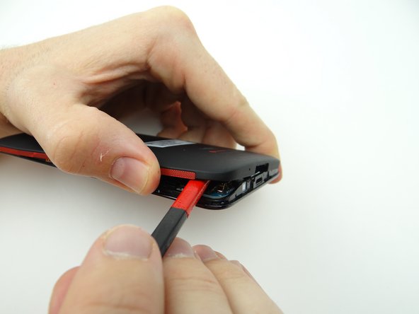
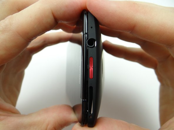
Picture 2: Slowly work your way around the corner gently prying up as you go.
-
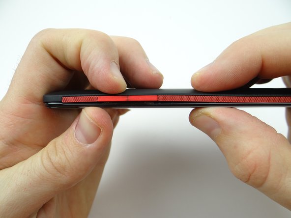
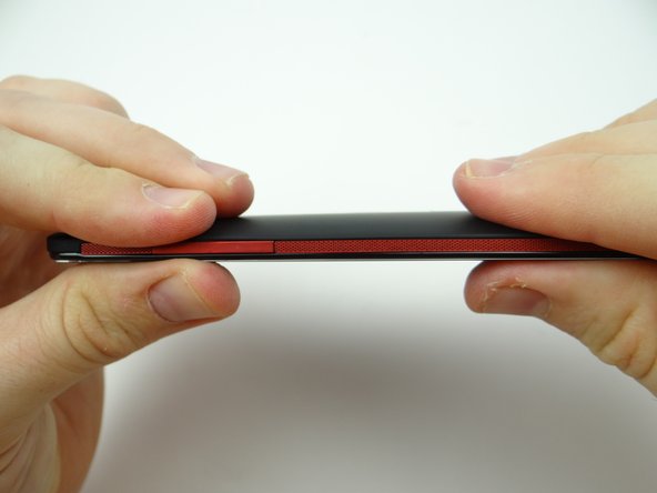
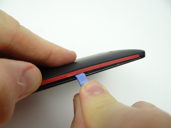
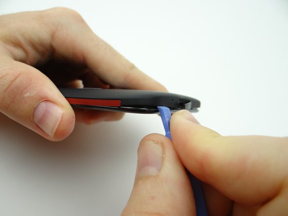
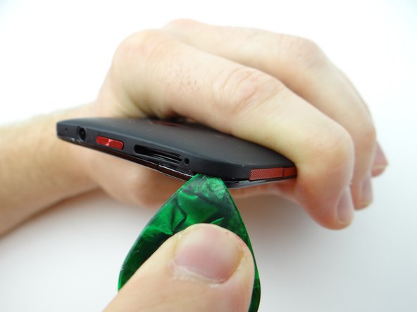
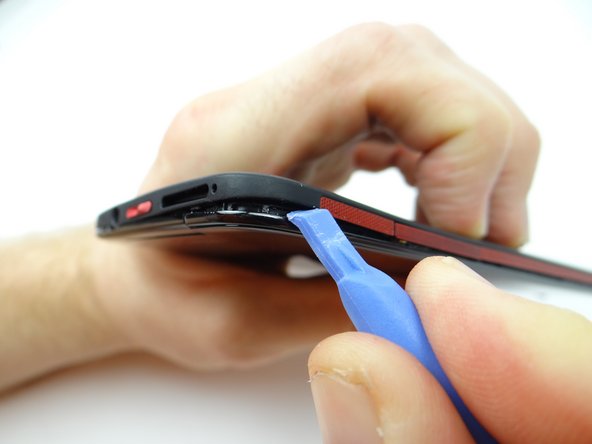
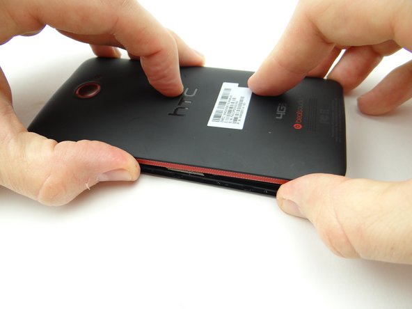
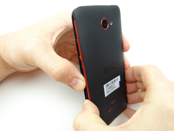
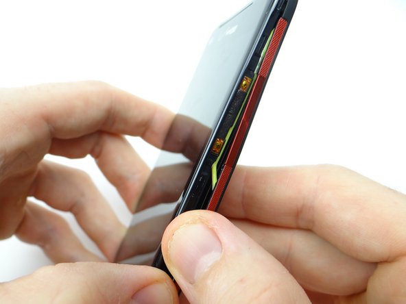
Picture 3: Work your way up the side (the side opposite the volume rocker), holding the battery cover up with your thumb.
-
-
-
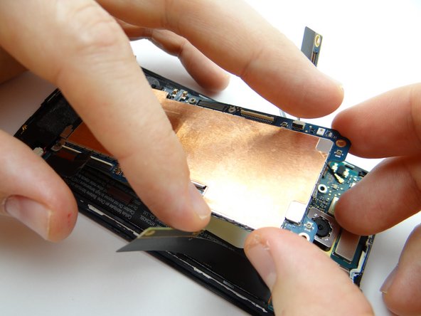
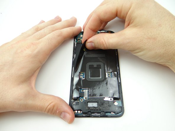
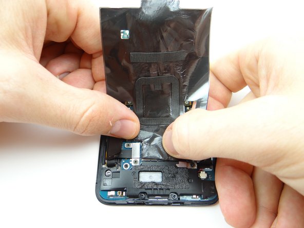
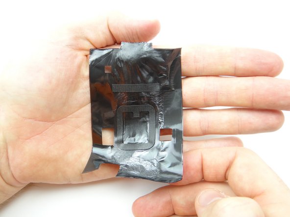
Pinch the black tape covering the logic board in the upper-left corner.
-
Gently peel it away from the phone.
-
Place the black tape in ZONE I on top of the battery cover.
-
-
-
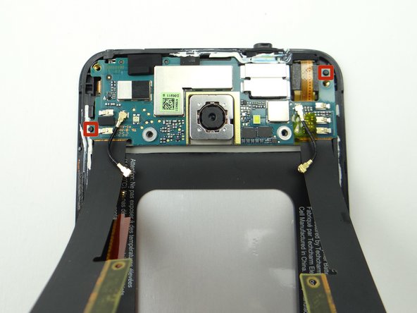
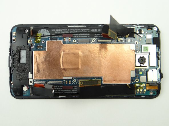
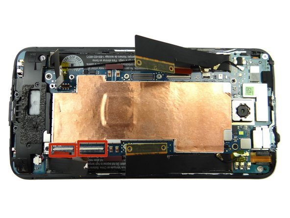
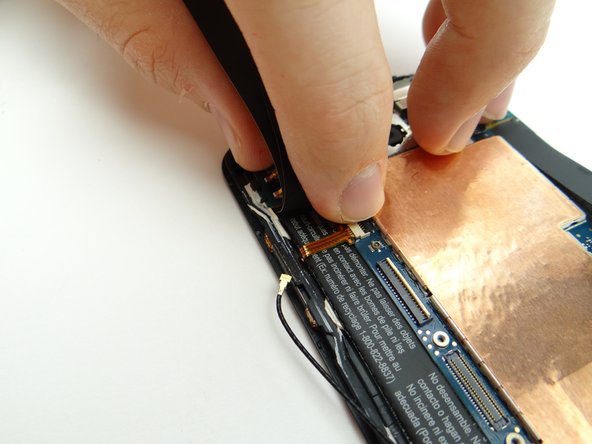
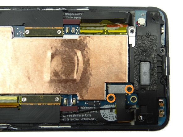
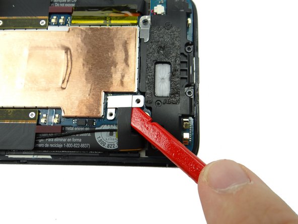
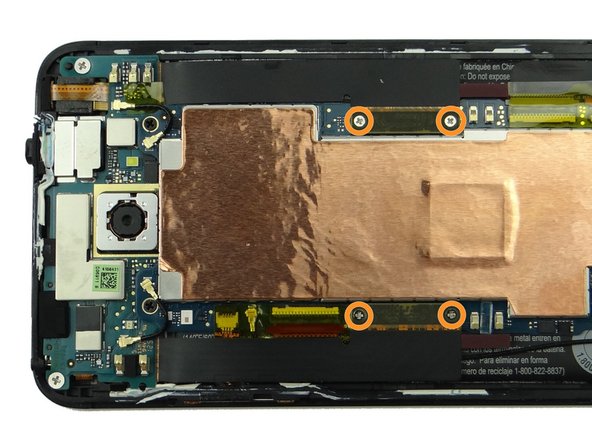
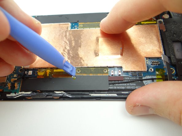
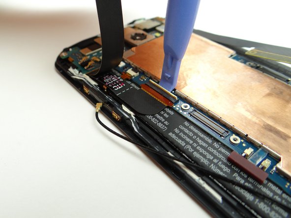
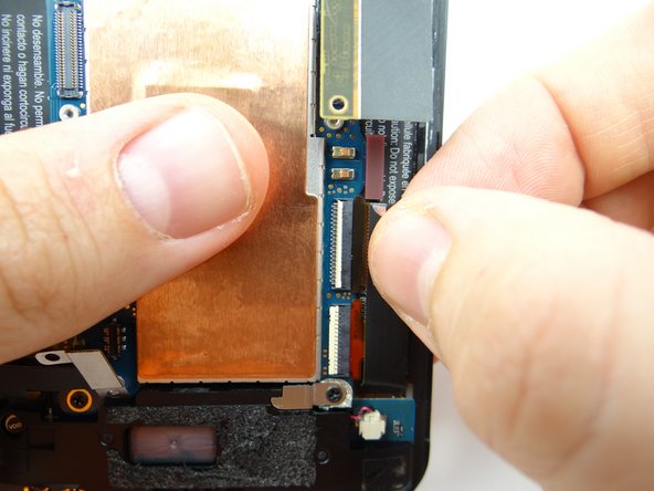
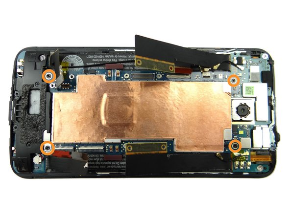
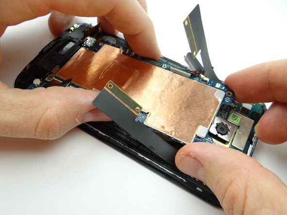
Picture 1: Remove four 1.6 mm Phillips #00 screws securing the two large daughter board flex cables. Place in SLOT 2.
-
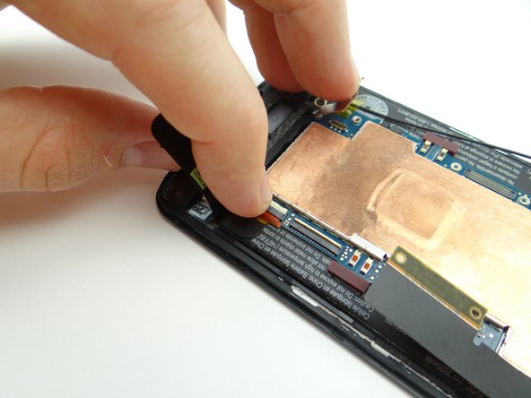
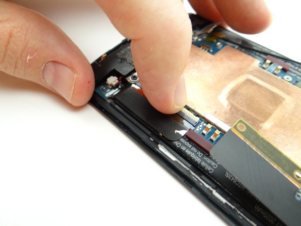
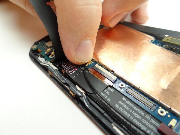
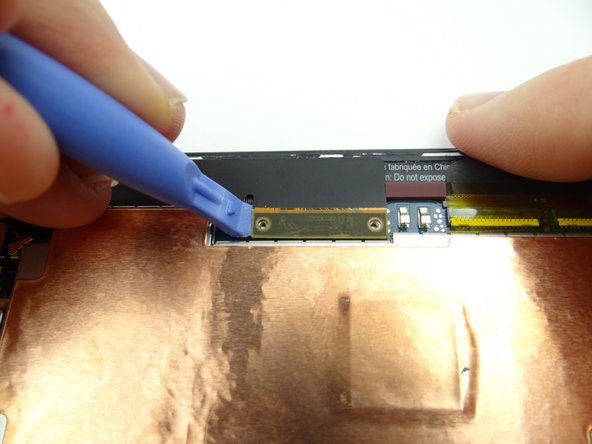
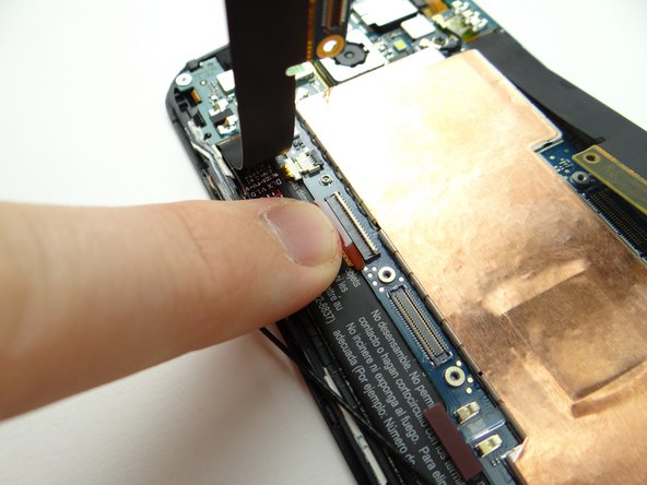
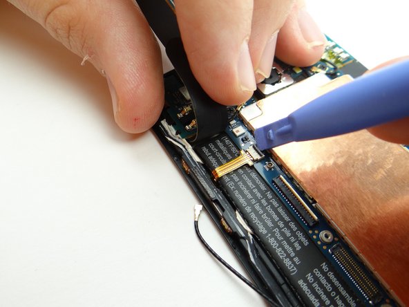
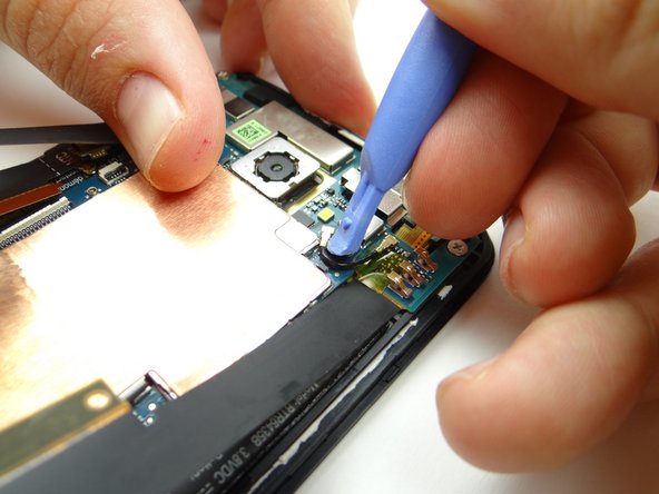
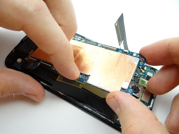
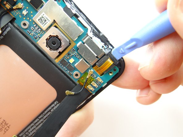
Pictures 2 & 3: Use the blue pry tool to disconnect the two large daughter board flex cables from the main logic board.
-
-
-
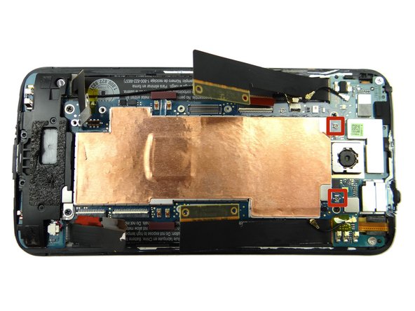
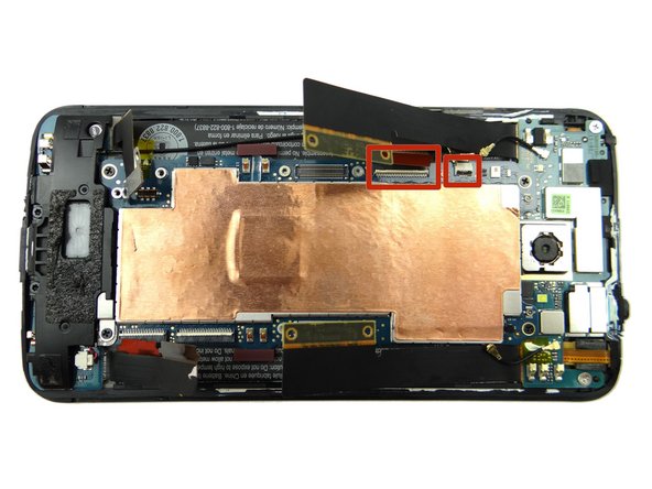
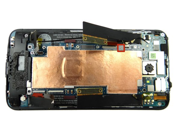
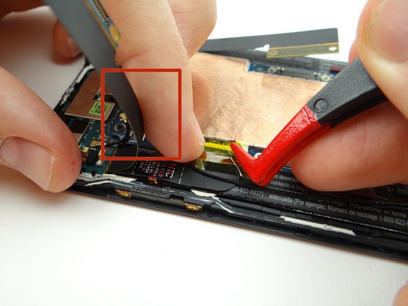
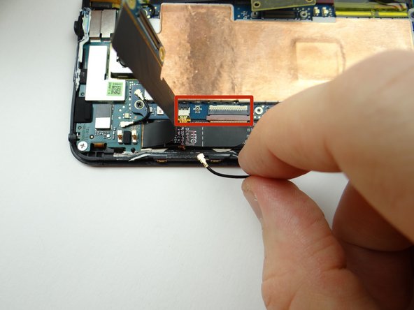
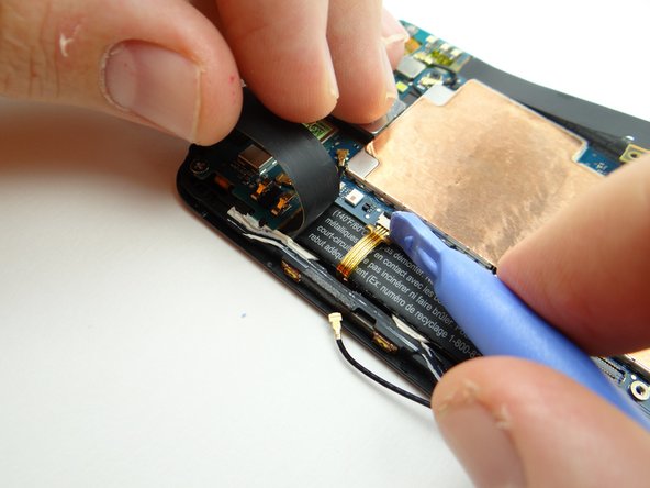
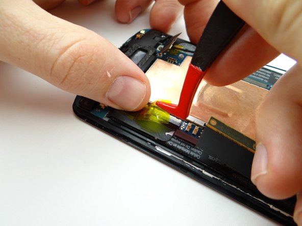
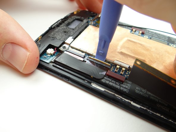
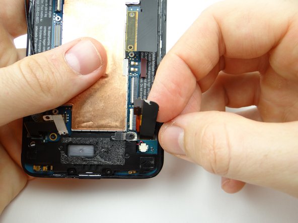
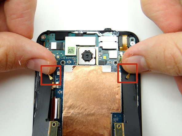
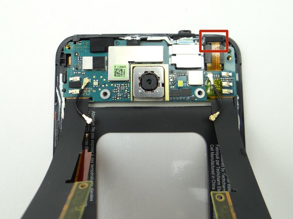
Hold the left daughter board flex cable up (red square in Picture 1) to expose cables:
-
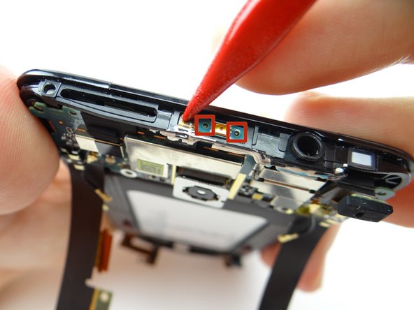
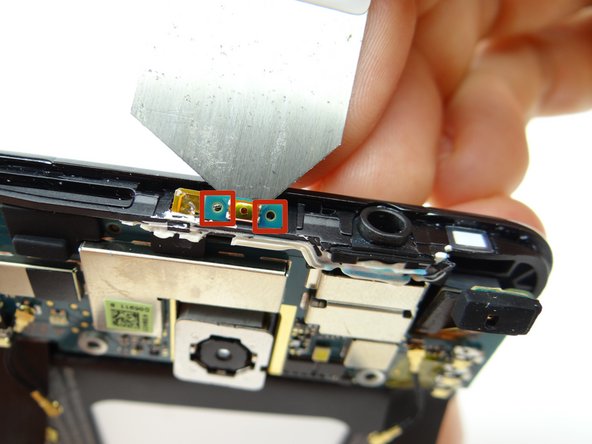
Picture 1: Peel up Kapton tape covering ZIF connectors & antenna connector.
-
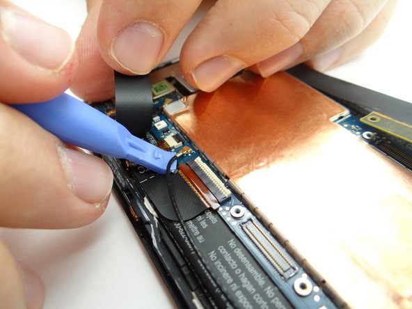
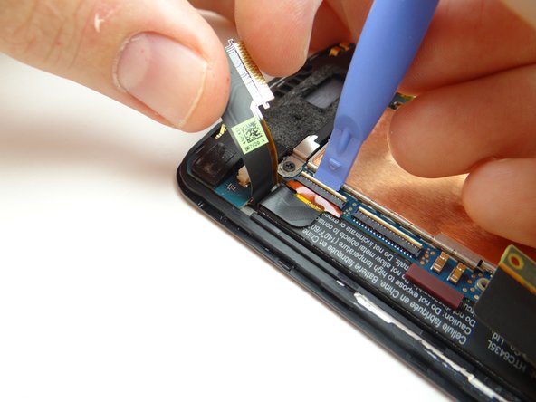
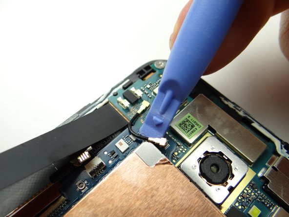
Picture 2: Disconnect antenna cable with the blue pry tool placed exactly where shown.
-
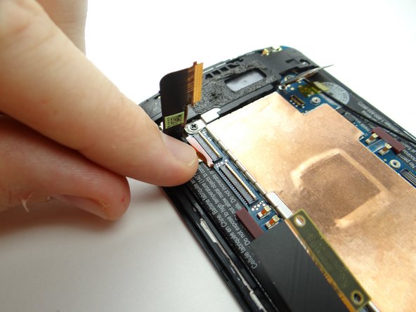
Picture 3: Move antenna cable out of the way to access the ZIF connectors on either side of the antenna connector.
-
-
-
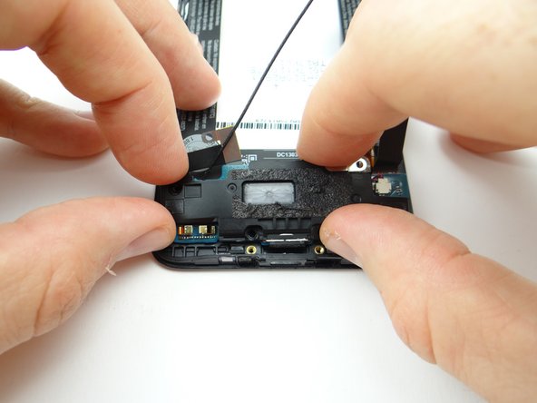
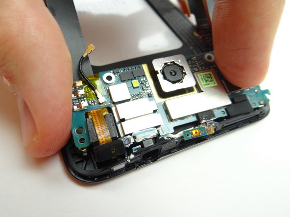
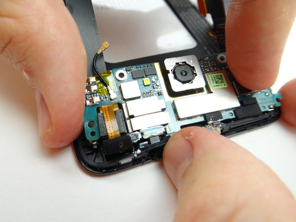
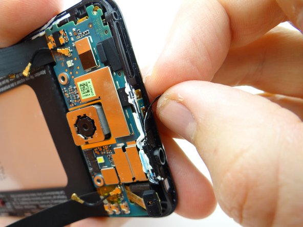
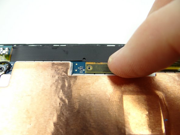
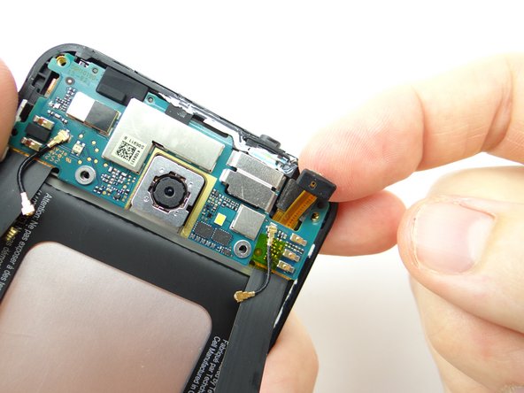
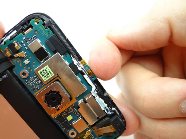
Pictures 1 & 2: Wedge the flat end of the spudger under the daughter board where shown. Lift up slightly.
-
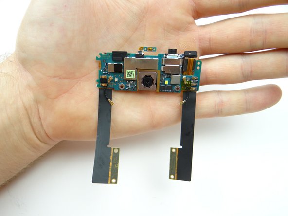
Rear camera is connected to underside of logic board:
-
Picture 3: While lifting the right side of the daughter board with the spudger, pull the rear camera up from its socket with your thumb.
-
-
-
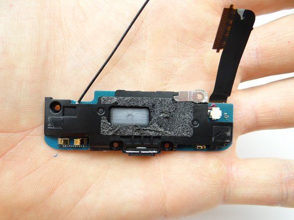
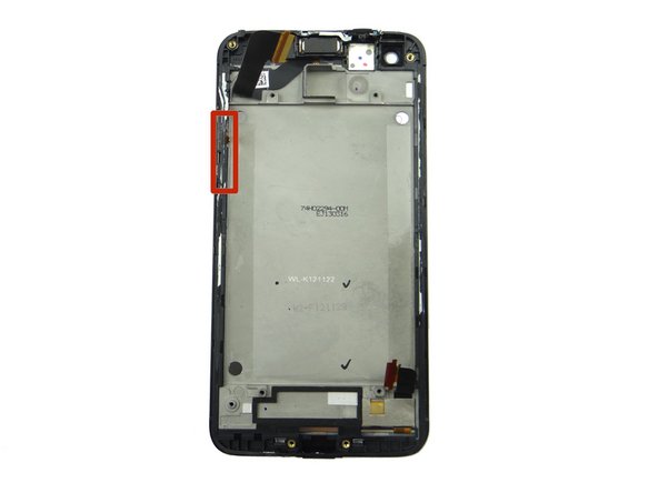
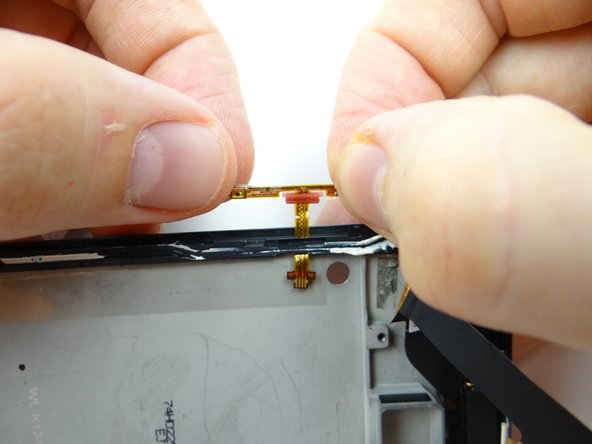
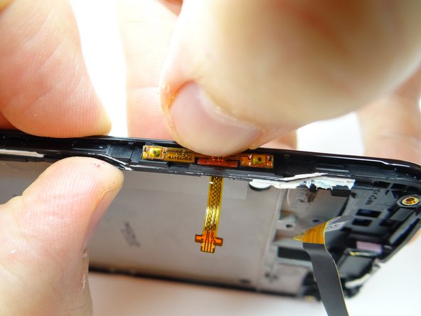
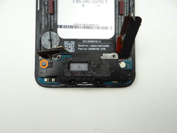
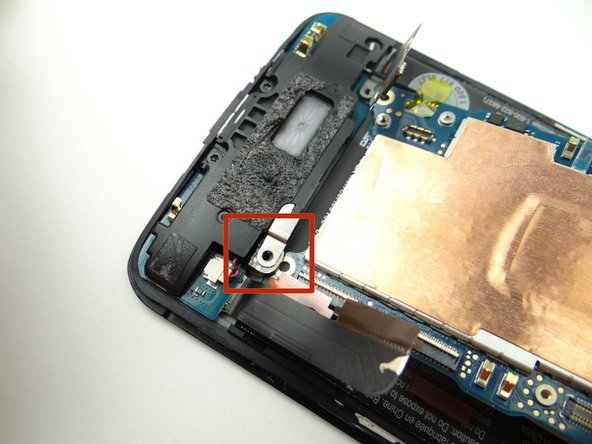
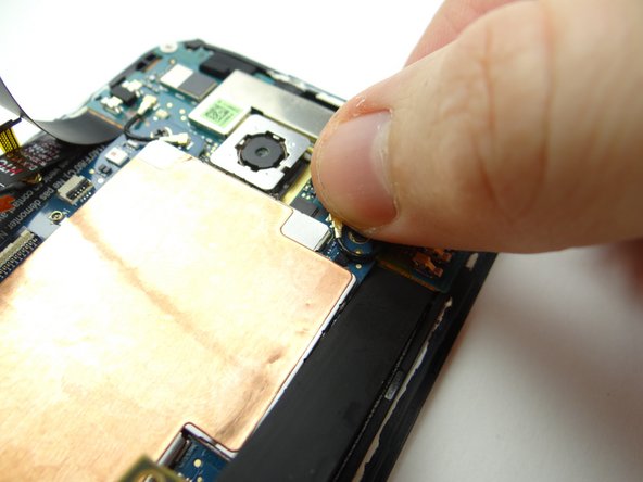
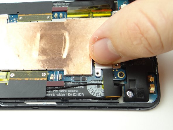
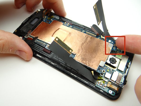
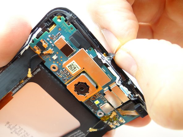
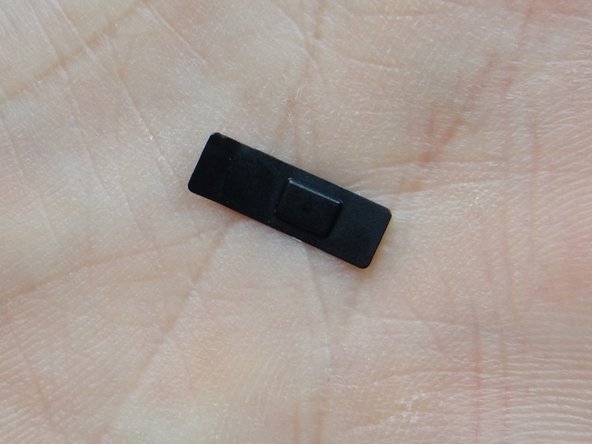
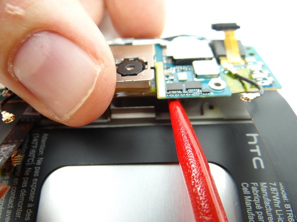
Remember, the power button contact (red square) is attached to the daughter board:
-
Lift the bottom of the daughter board with your finger, while using the blue pry tool to lift the power button contact away from the mid-frame.
-
Place daughter board or front panel (depending on the repair needed) in ZONE III.
-
-
-
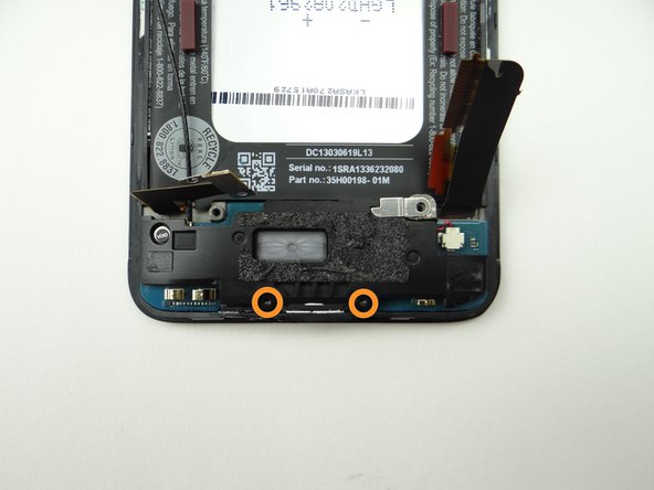
Picture 1: Remove 2.7 mm Phillips #00 'void sticker screw'. Place in SLOT 5.
-
Picture 2: Remove two 4.0 mm T5 Torx screws. Place in SLOT 6.
-
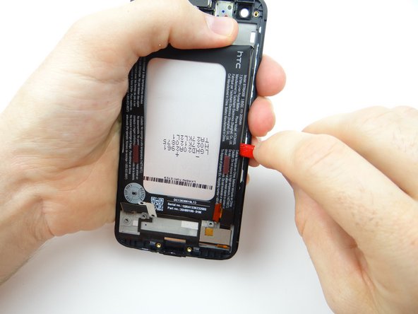
Picture 3: Pivot antenna cable from under the battery cover [to over it as shown].
-
-
-
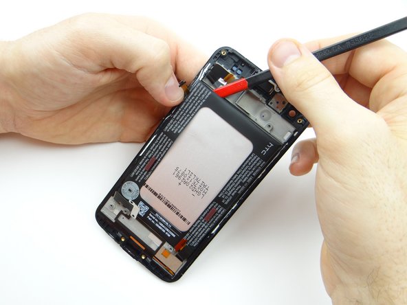
Picture 1: There are adhesive strips running down either side of the battery.
-
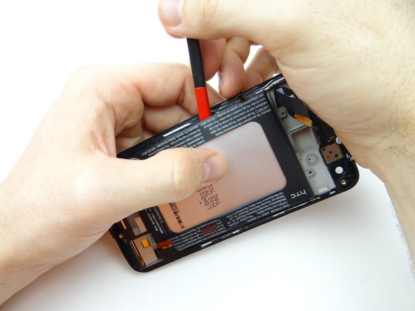
Picture 2: Use the flat end of the spudger to push halfway down the adhesive.
-
Picture 3: Pivot the spudger sideways to continue cutting through the adhesive.
-
-
-
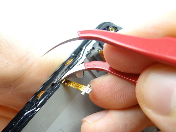
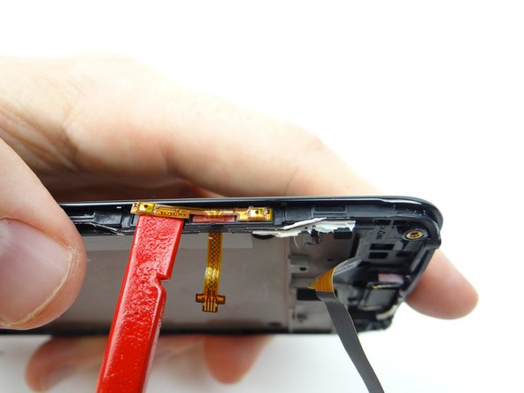
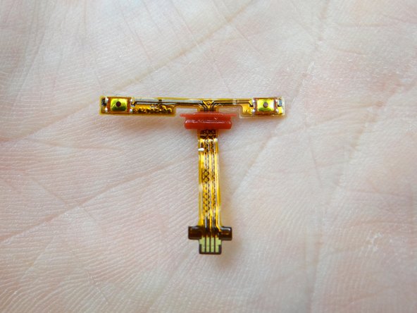
Remove the volume rocker contact cable:
-
Use one prong of curved-tip tweezers to lift edge of the tape covering volume contacts cable.
-
Picture 3: Peel the tape away with your fingers. Place on the back wall of COMPARTMENT C.
-
-
-
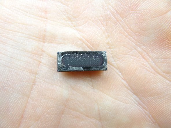
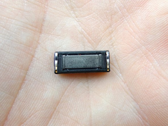
The earpiece speaker is fragile and held down by fairly strong adhesive:
-
If you're discarding the display (and reusing the earpiece speaker), use one prong of the metal tweezers to wedge against the top edge of the earpiece speaker. Rotate the speaker out of its socket.
-
If you're replacing the earpiece speaker, just yank it up by the metal contacts on either side.
-
Place in COMPARTMENT D.
-
-
-
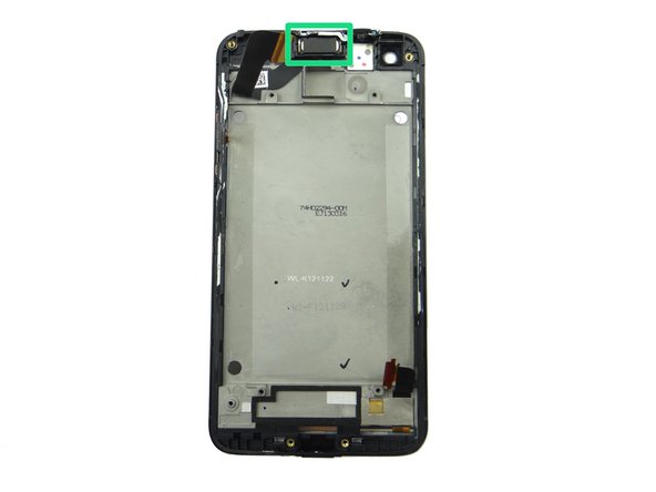
Retrieve display assembly, then:
-
Replace earpiece speaker from COMPARTMENT D.
-
-
-
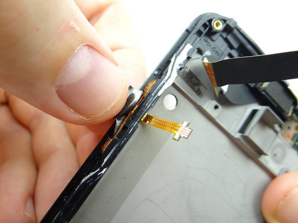
Replace volume rocker contacts cable from COMPARTMENT C.
-
Feed the cable through the slot on the mid-frame, then seat it as shown in Picture 3.
-
-
-
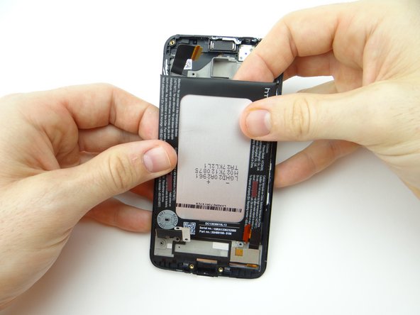
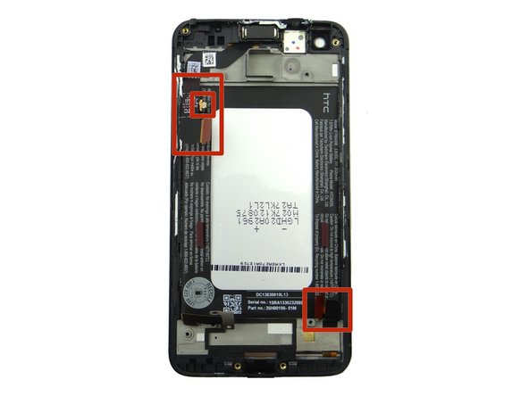
Seat the battery.
-
Make sure the LCD, volume rocker, and digitizer cables aren't trapped under the battery (red squares).
-
-
-
Replace charging port assembly.
-
Tuck antenna cable under battery connector.
-
-
-
From ZONE II, replace logic board.
-
Make sure the opening on the logic board sits under the tab on the charging port (red square).
-
Brush cables out of the way as you continue seating the logic board.
-
-
-
Seat battery cable.
-
Replace two 1.5 mm Phillips #00 screws from SLOT 1.
-
-
-
From ZONE I, replace battery cover:
-
Pictures 1 & 2: Align tabs first.
-
Picture 3: Push top of battery cover into place.
-


![Picture 3: Pivot antenna cable from under the battery cover [to over it as shown].](https://d3t0tbmlie281e.cloudfront.net/igi/sandbox/YNDDLnN3i6yQHRyD.medium)