Parts
No parts specified.
-
-
Before disassembling the Samsung Galaxy S4, thoroughly wash and dry your hands.
-
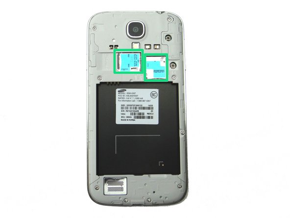
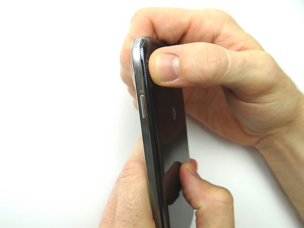
Picture 1: Remove the battery cover using the notch at the upper left-hand corner. Remove the battery too and place both into ZONE I.
-
Picture 2: Remove SIM card and SD card. Place in COMPARTMENT A.
-
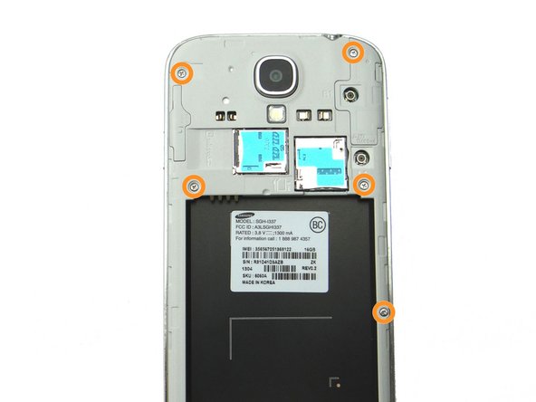
Picture 3: Remove four 4.0 mm Phillips screws. Place in SLOT 1.
-
-
-
Picture 1: Remove five 4.0 mm Phillips screws. Place in SLOT 1.
-
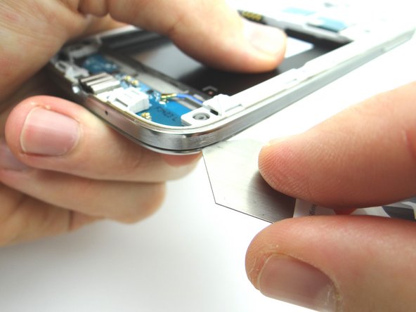
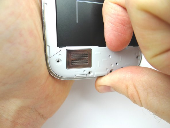
Picture 2: Use the iSesamo to create enough separation between the mid-frame and the front panel assembly to wedge a Blue Pry Tool between the two.
-
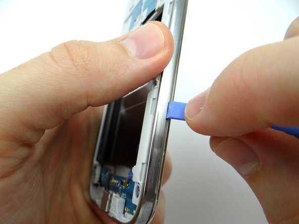
Picture 3: After you create enough separation, wedge the Blue Pry Tool between mid-frame and front panel. Move the Blue Pry Tool up the right side and around each edge of the phone, popping the clips holding the mid-frame to the front panel along the way.
-
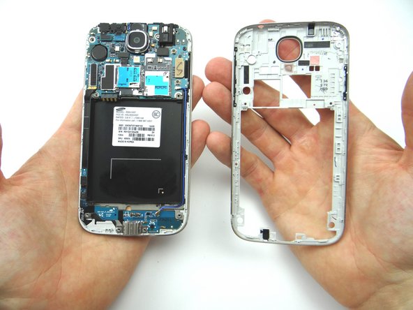
Place mid-frame into ZONE II.
-
-
-
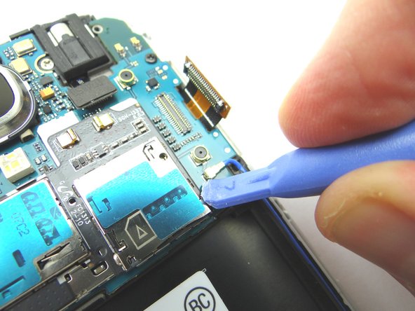
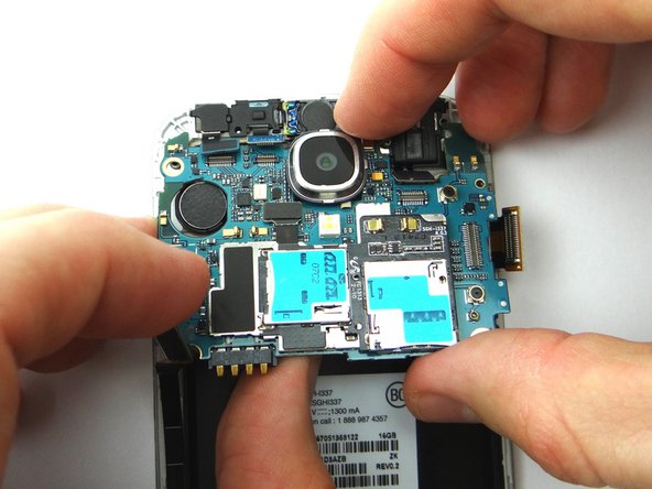
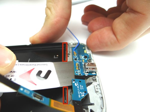
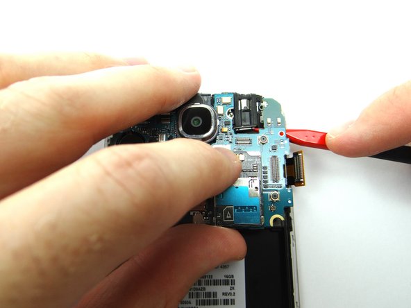
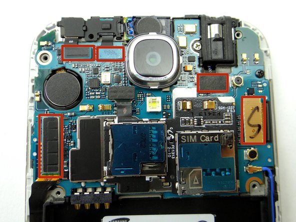
Picture 1: Using the Blue Pry Tool, disconnect five cable connectors on the logic board.
-
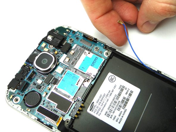
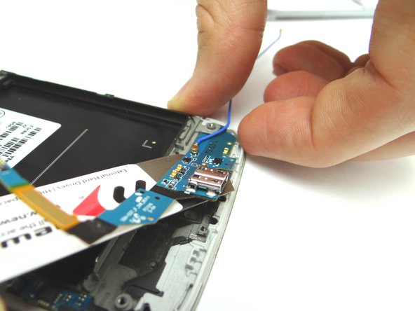
Picture 2: Disconnect the antenna cable.
-
-
-
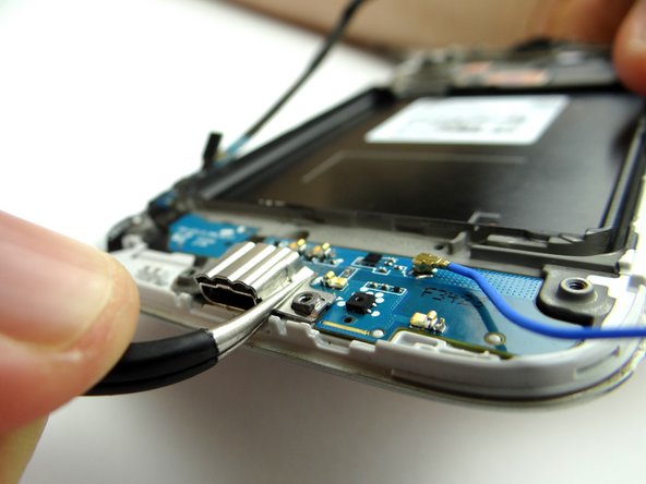
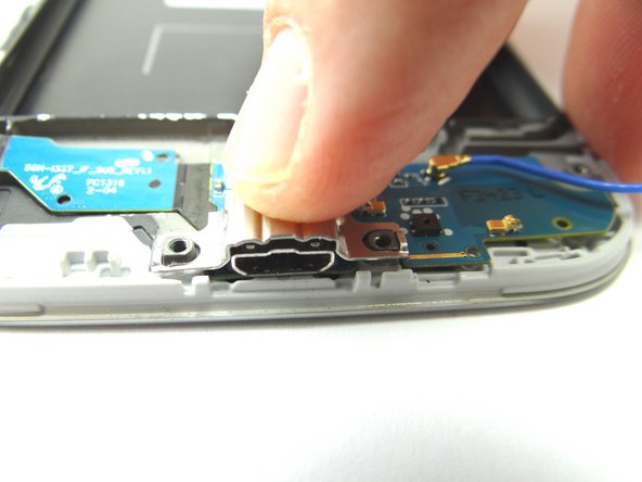
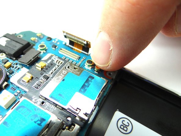
Picture 1: Use the Curved Tip Tweezers to remove the metal plate covering the charging port. You will have to apply a fair amount of force to free the plate. Place it in SLOT 3.
-
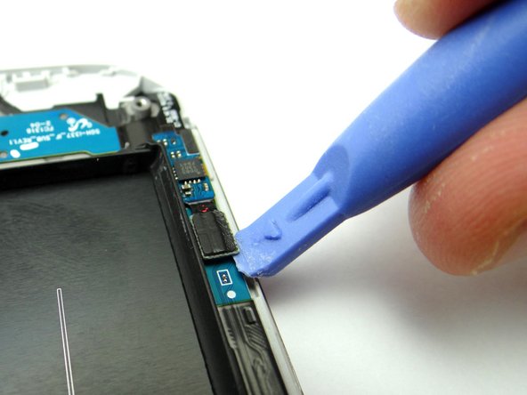
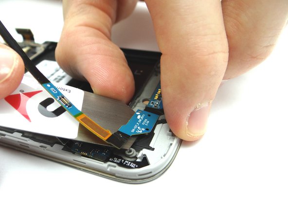
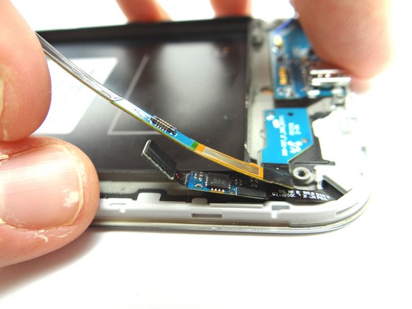
Picture 2: Use the Blue Pry Tool to disconnect the soft keys ribbon from the charging port ribbon.
-
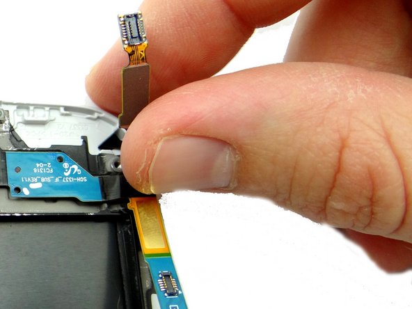
Picture 3: The soft keys ribbon is adhered to the charging port ribbon - use your fingers to peel them apart.
-
-
-
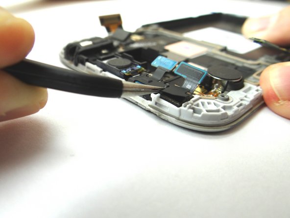
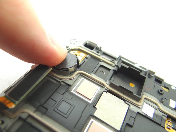
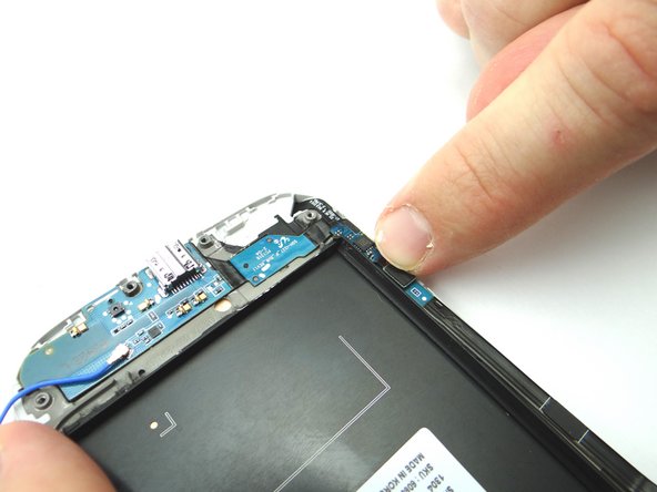
With the top of the phone facing your body, grab the metal shield with the Curved Tip Tweezers. Peel up the clip to your right first, then the bottom left and finally the top left. Place clip into SLOT 4.
-
-
-
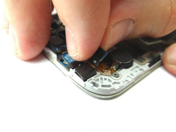
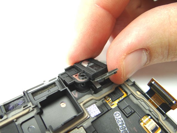
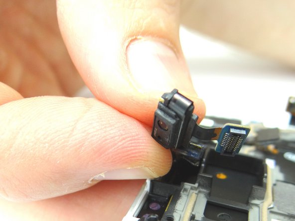
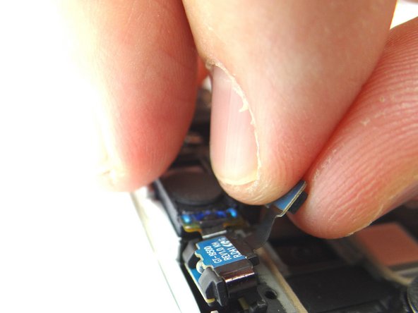
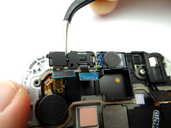
Use your fingers to remove the proximity sensor / earpiece speaker assembly.
-
Picture 1: Slowly pull the sensor free first, working from left to right
-
Picture 2: Then peel the earpiece speaker free and place the assembly into COMPARTMENT E.
-
-
-
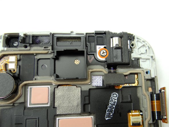
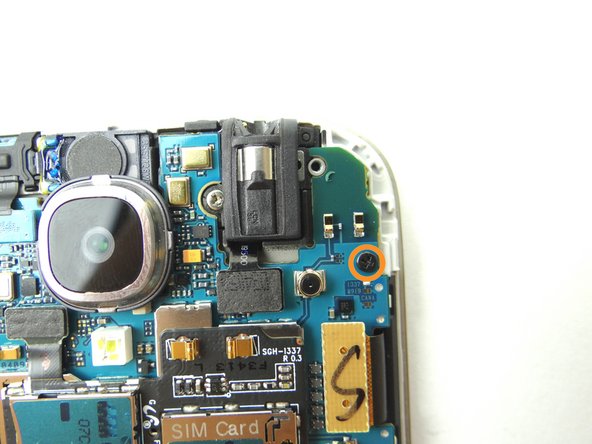
Remove one 2.2 mm Phillips screw and place into SLOT 5.
-
Use your fingers to remove the headphone jack and place into COMPARTMENT F.
-
-
-
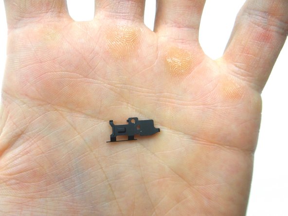
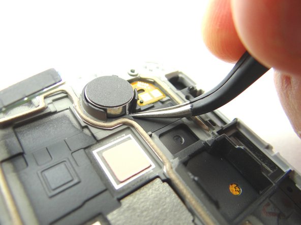
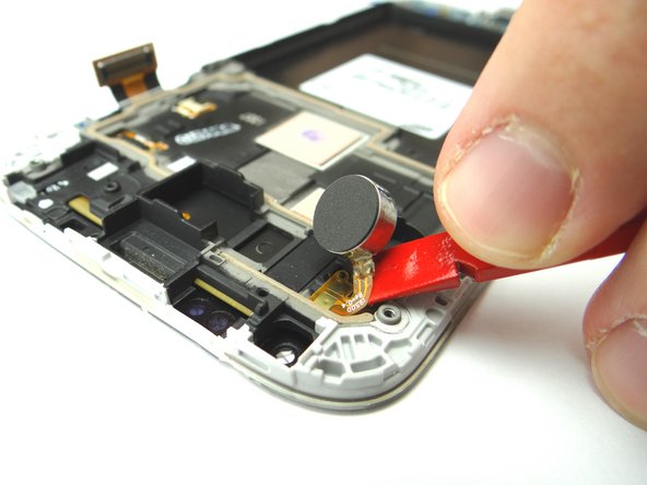
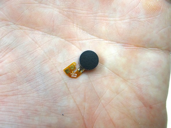
Picture 1: Wedge the Curved Tip Tweezers in the closed position under the vibrator. Pry up to free the vibrator from the adhesive holding it to the front panel assembly.
-
Once the vibrator is free from the adhesive, use the Black Spudger to gently pry up the vibrator ribbon contacts. Place the vibrator in COMPARTMENT G.
-
-
-
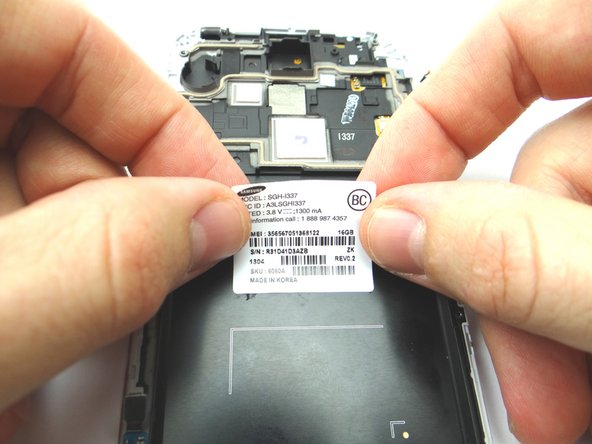
Apply heat to the IMEI sticker for approximately 40 seconds to loosen the adhesive.
-
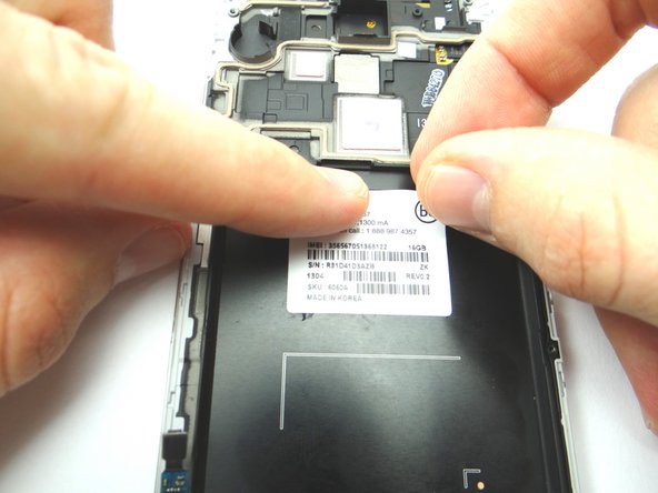
Using Curved Tip Tweezers, peel up the upper-left hand corner of the IMEI Sticker.
-
Once you have enough space to pinch the corner, peel the sticker free with your fingers.
-
-
-
Place the IMEI sticker on the new display assembly and smooth out with your fingers.
-
-
-
Replace the headphone jack from COMPARTMENT F.
-
Replace one 2.2 mm Phillips screw from SLOT 5.
-
-
-
Replace the proximity sensor / earpiece speaker assembly from COMPARTMENT E.
-
-
-
Replace the front-facing camera from COMPARTMENT D.
-
Use the Curved Tip Tweezers to replace the metal plate from SLOT 4.
-
-
-
Replace the charging port board from COMPARTMENT C.
-
From SLOT 3, use your finger to replace the metal plate that covers the charging port.
-
Reconnect the soft keys ribbon cable to the charging port ribbon cable with your finger.
-
-
-
Picture 1: Replace the logic board from ZONE III.
-
Picture 2: You may have to use the Black Spudger to feed the headset jack cable through to the top of the logic board.
-
Picture 3: Replace one 2.4 mm Phillips screw from SLOT 2.
-
-
-
Replace the mid-frame from ZONE II.
-
Secure the mid-frame with five 4.0 mm Phillips screws from SLOT 1.
-
-
-
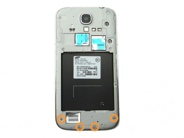
Picture 1: Replace the loudspeaker from Compartment B.
-
Picture 2: Replace four 4.0 mm Phillips screws from SLOT 1.
-
Picture 3: Replace SIM card and SD card from COMPARTMENT A.
-