-
-
Before disassembly, thoroughly wash and dry your hands.
-
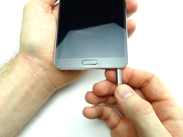
Remove the stylus, battery cover and battery. Place in ZONE I.
-
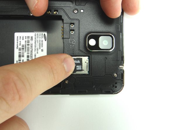
Remove SIM card and SD card. Place in COMPARTMENT A.
-
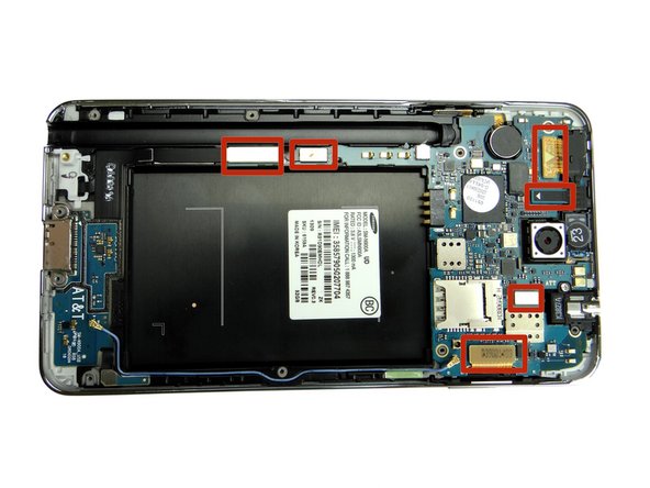
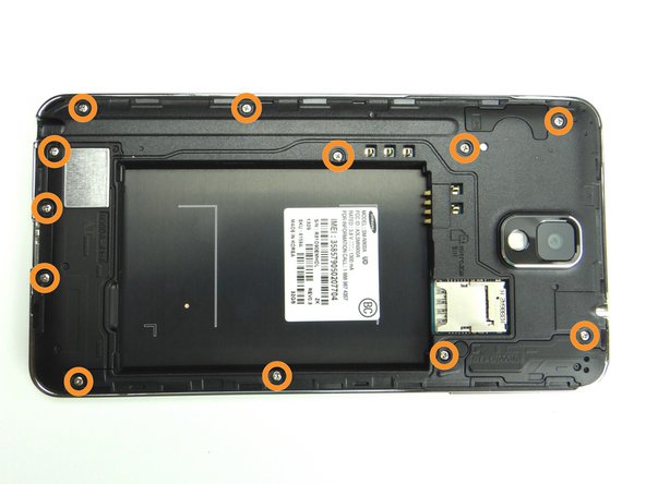
Remove twelve 4.0 mm #00 Phillips screws. Place in SLOT 1.
-
-
-
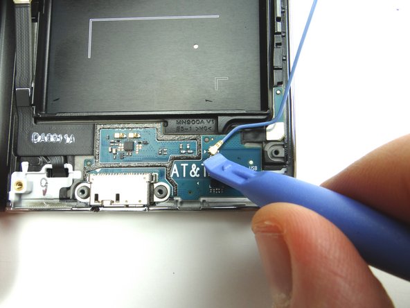
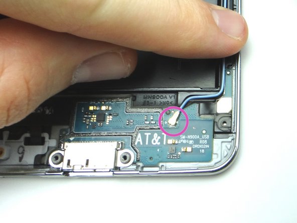
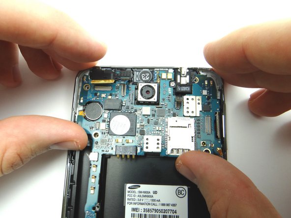
Use the Blue Pry Tool to disconnect six ribbon cable connectors on the logic board.
-
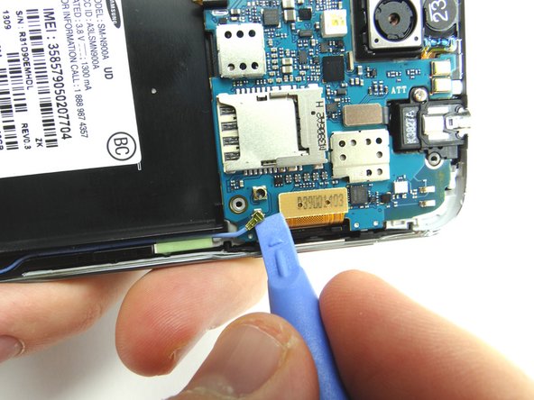
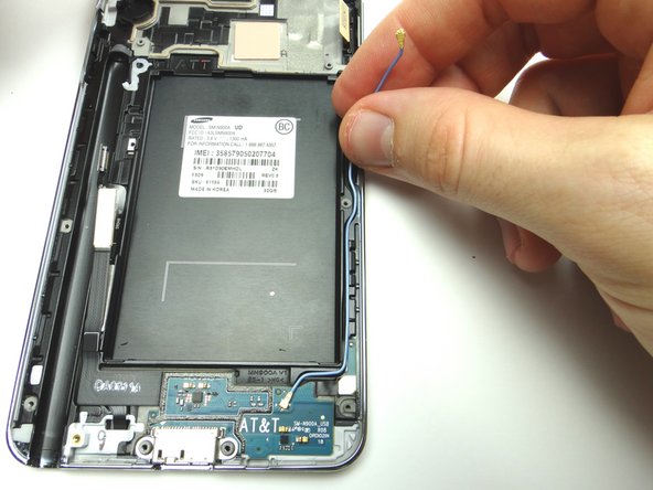
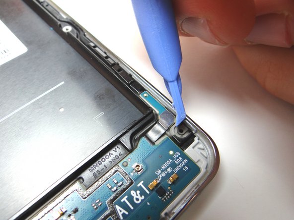
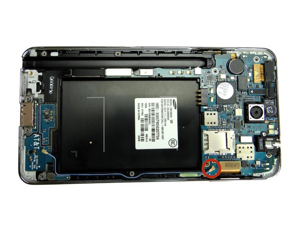
Disconnect the antenna cable using the blue pry tool as shown in Picture 2.
-
-
-
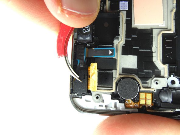
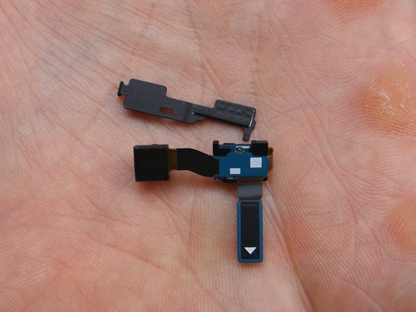
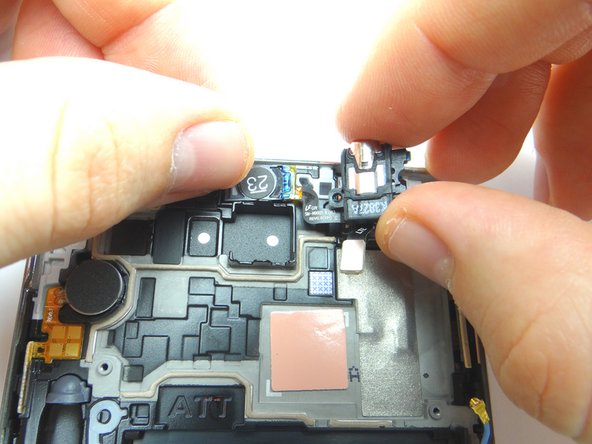
The front-facing camera and proximity sensor are one assembly as shown in Picture 3:
-
Use curved tip tweezers to remove the metal bracket covering the front-facing camera and proximity sensor assembly.
-
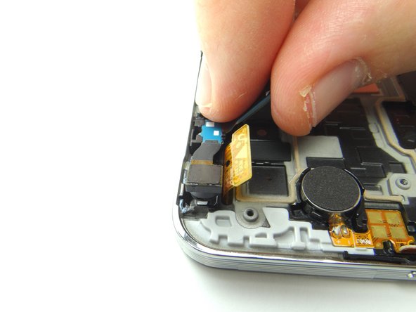
Gently peel up the proximity sensor on the right. Once it's free, continue peeling right-to-left to free the front-facing camera.
-
Place the bracket and assembly in COMPARTMENT C.
-
-
-
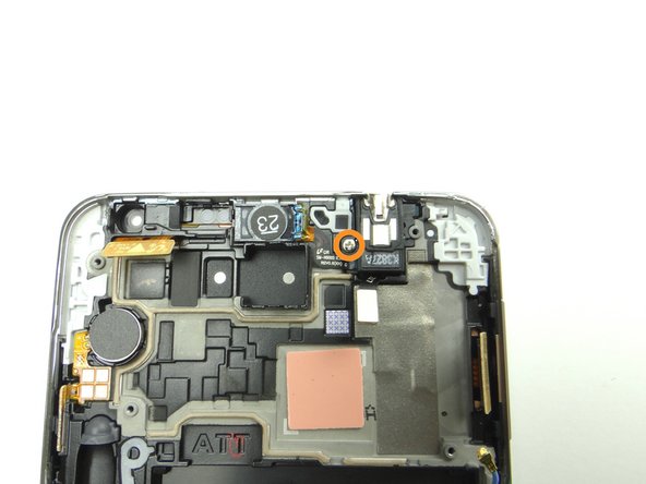
Remove 3.0 mm Phillips screw from headset jack assembly. Place screw in SLOT 2.
-
-
-
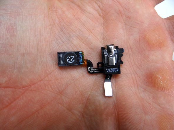
The earpiece speaker and headset jack are one assembly, shown in Picture 3:
-
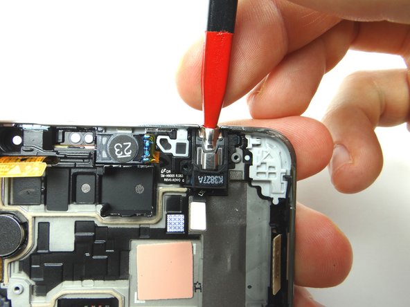
Use the pointed end of the spudger to gently pry up the headset jack.
-
Loosen the headset jack, but don't pull the assembly free just yet.
-
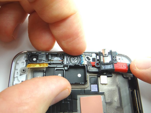
Wedge the spudger under the earpiece speaker. Then gently peel up the assembly with your fingers until its free.
-
Place the headset jack and earpiece speaker assembly in COMPARTMENT D.
-
-
-
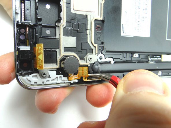
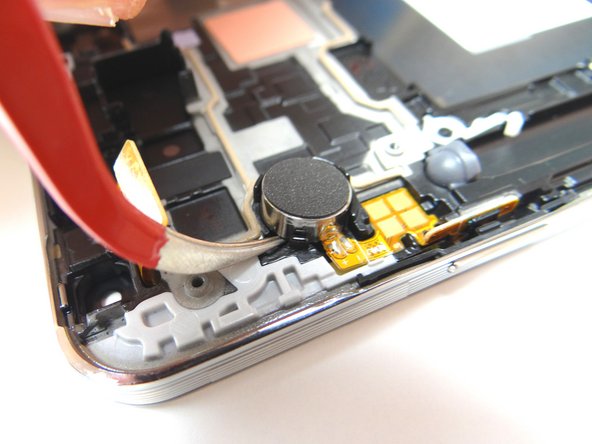
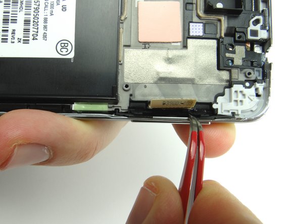
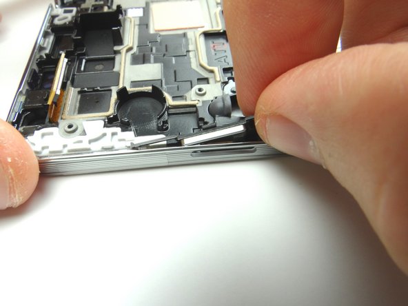
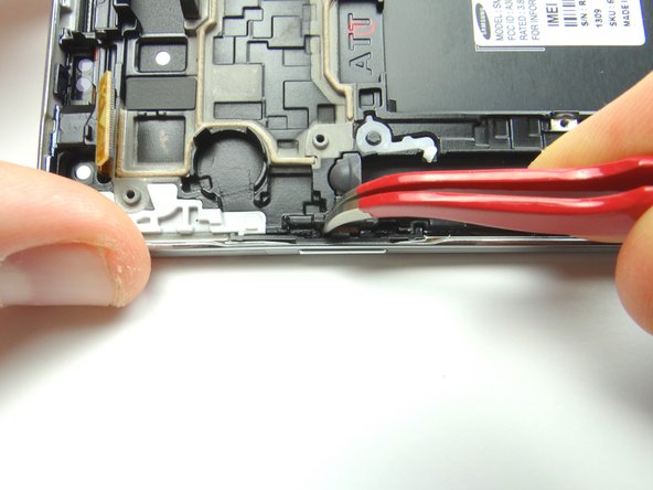
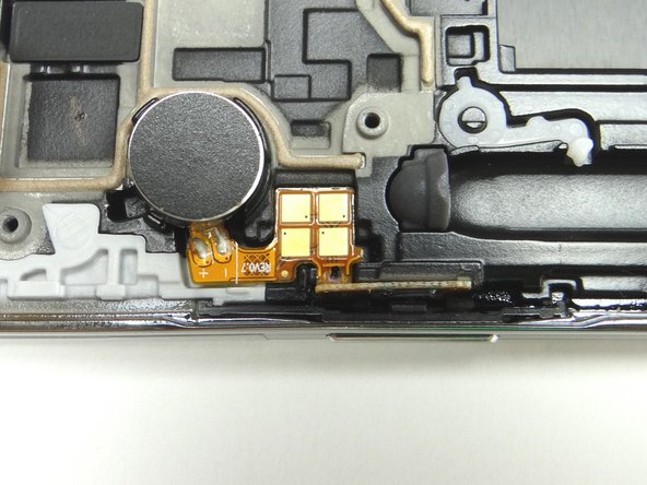
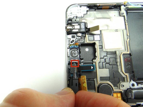
Wedge the Curved Tip Tweezers in the closed position under the contact pad connected to the vibrator and pry up to loosen it.
-
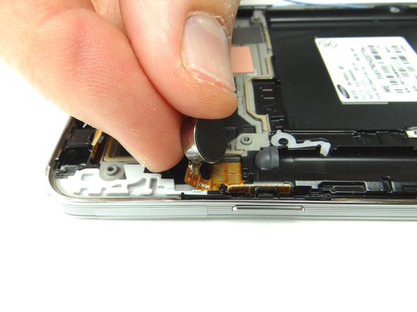
Now wedge the tweezers under the vibrator and pry up to loosen it, but don't remove it just yet.
-
-
-
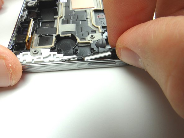
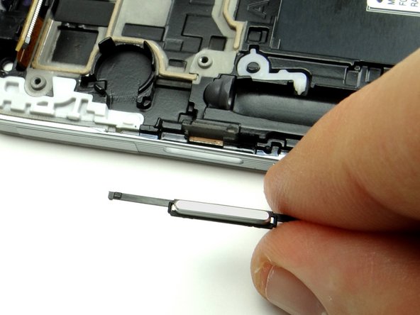
Remove the volume rocker and place it with the power button in COMPARTMENT F.
-
-
-
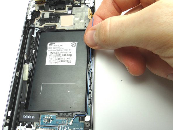
Unthread the antenna from the front panel.
-
Disconnect the antenna cable using the blue pry tool and place it in ZONE IV.
-
-
-
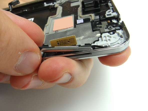
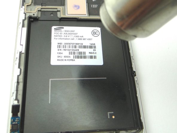
Apply heat to the IMEI sticker for approximately 30 seconds to loosen the adhesive.
-
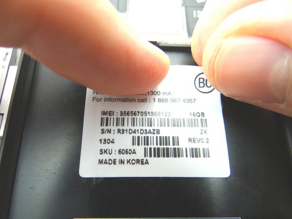
Use your finger nail or tweezers to lift the corner of the sticker and peel up. Move it immediately to the replacement part.
-
-
-
Place the IMEI sticker on the new display assembly and smooth out with your fingers.
-
-
-
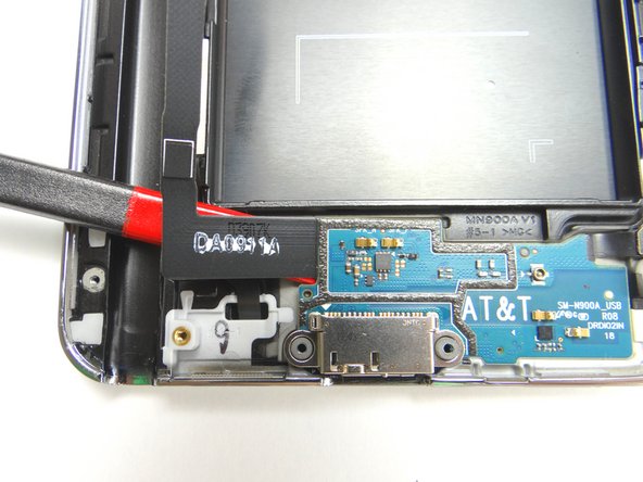
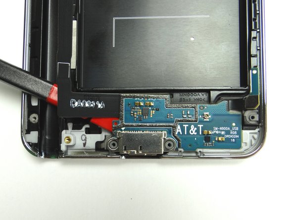
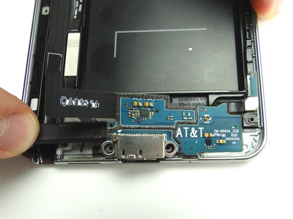
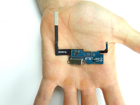
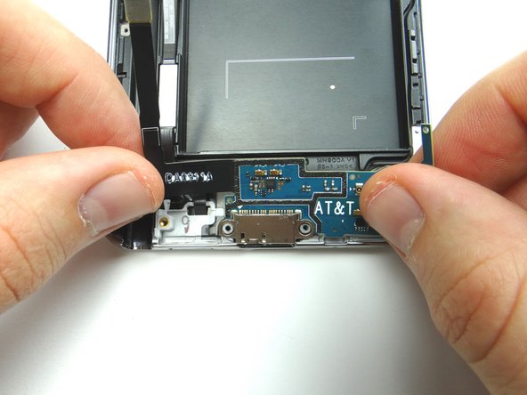
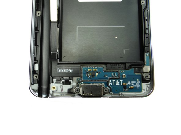
Replace the charging port from ZONE V.
-
Make sure the assembly is lined up squarely on the front panel.
-
-
-
Replace the volume button from COMPARTMENT F.
-
Use curved tip tweezers to press the button firmly into place.
-
-
-
From COMPARTMENT F, replace the power button.
-
Use curved tip tweezers to press the button firmly into place.
-
-
-
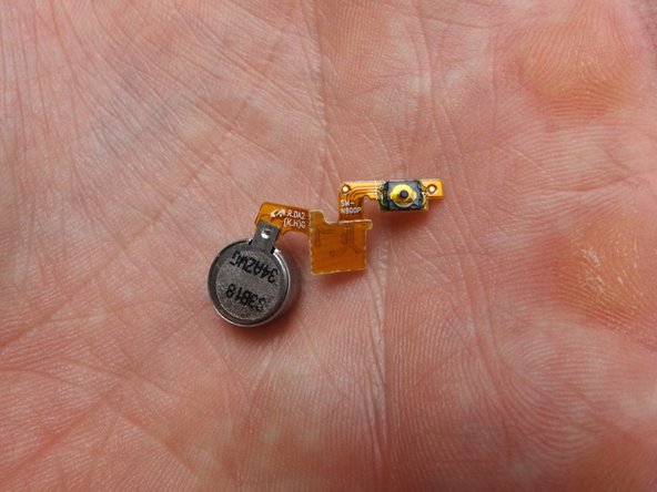
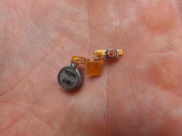
Replace the vibrator and power button cable from COMPARTMENT E.
-
Note the small black circular power button contact circled in Picture 2. It creates the 'click' of the power button and must be properly aligned for the power button to function.
-
Picture 3: Shows how to place the assembly.
-
Makes sure the power button 'clicks' before continuing reassembly.
-
-
-
Replace headset jack and earpiece speaker assembly from COMPARTMENT D.
-
Replace 3.0 mm screw from SLOT 2.
-
-
-
Replace front-facing camera and proximity sensor assembly from COMPARTMENT C.
-
Replace the bracket also in COMPARTMENT C.
-
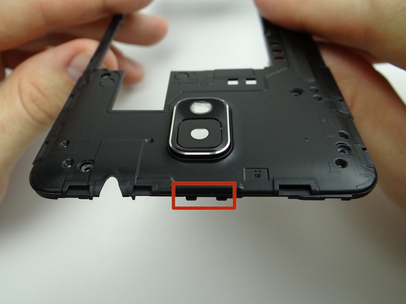
Make sure the tab on the right lines up with the slot on the front panel as in Picture 2 and the tiny metal stand is poking through the opening in the middle as shown in Picture 3.
-
-
-
Replace the logic board from ZONE III. Make sure no cables are trapped underneath the logic board.
-
Reseat six cables.
-
Reseat antenna.
-
-
-
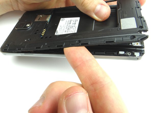
Replace mid-frame from ZONE II. Note the clips at the top of the mid-frame.
-
Place the mid-frame clips in their slots at the top of the front panel before seating the rest of the mid-frame.
-