-
-
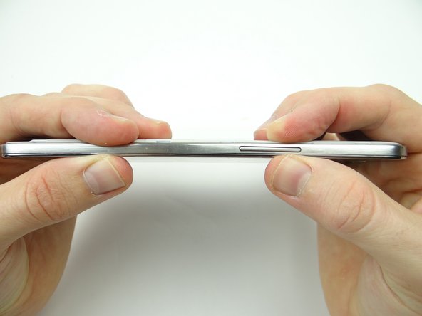
Power down device.
-
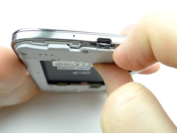
Use the notch above the power button to remove the battery cover. Place in ZONE V.
-
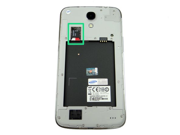
Remove the SIM card and SD card. Place both in Sandbox COMPARTMENT A.
-
-
-
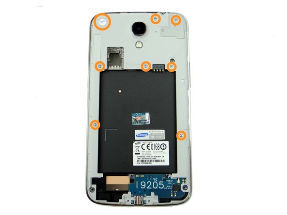
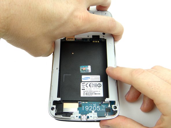
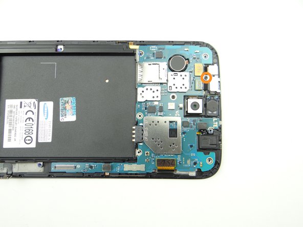
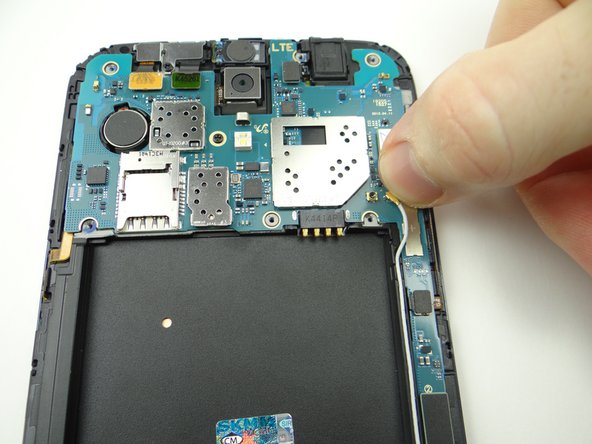
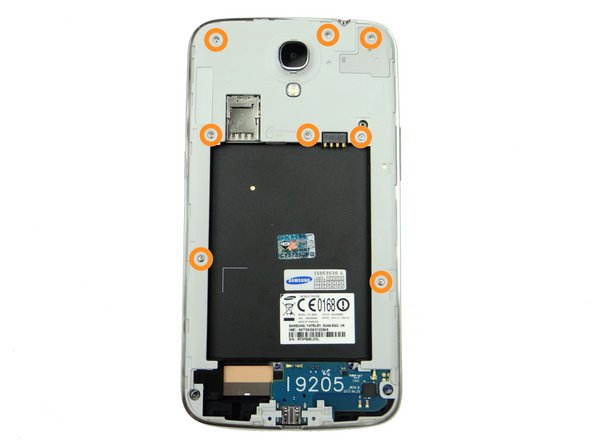
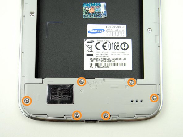
Picture 1: Remove eight 3.4 mm #00 Phillips screws. Place in SLOT 1.
-
Note the Samsung warranty sticker (large circle) in the upper-left corner. Remove it - there's a screw underneath.
-
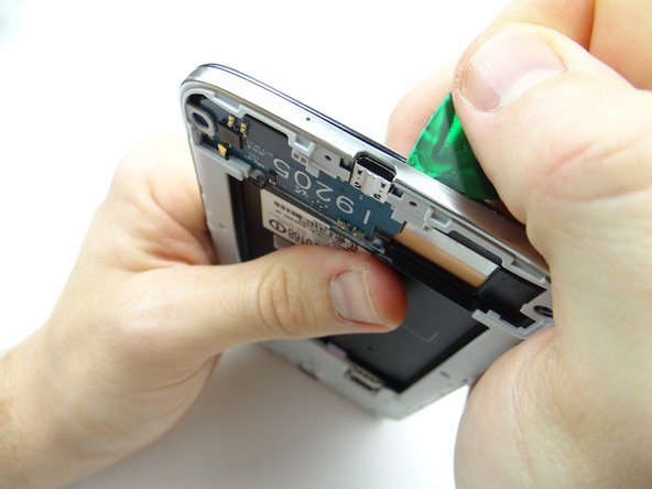
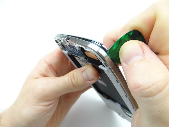
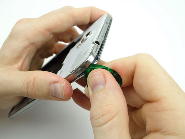
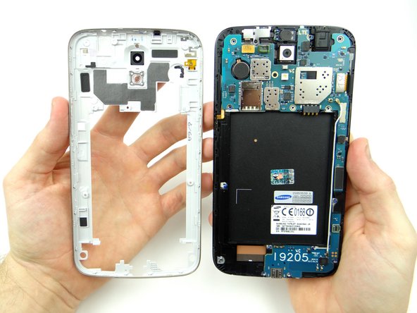
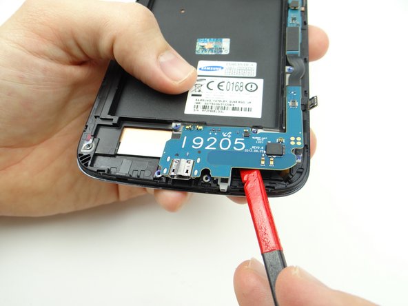
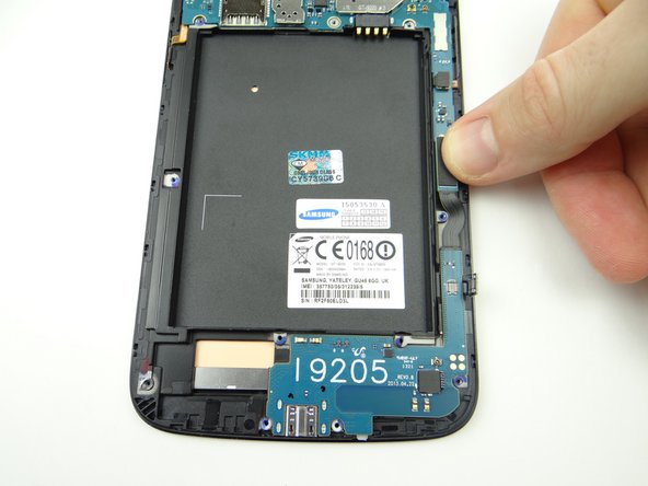
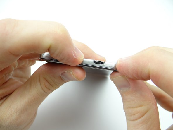
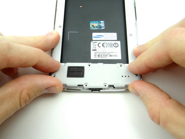
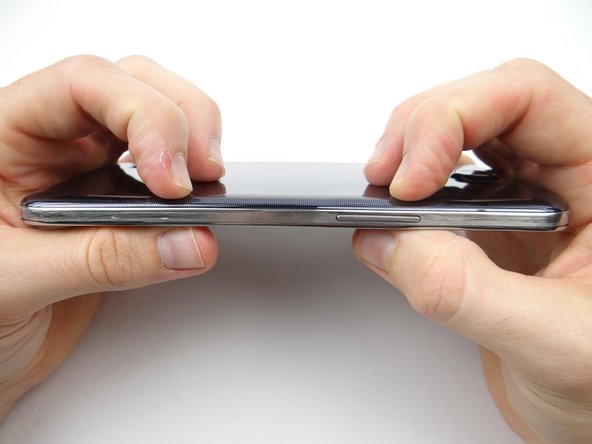
Picture 2: Note the orientation of the phone: insert guitar pick just right of the charging port between the mid-frame and front panel.
-
The mid-frame is thin and weaker under the charging port.
-
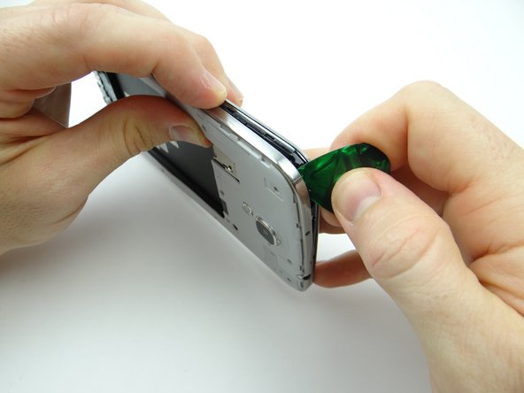
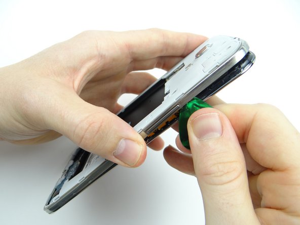
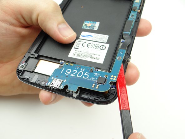
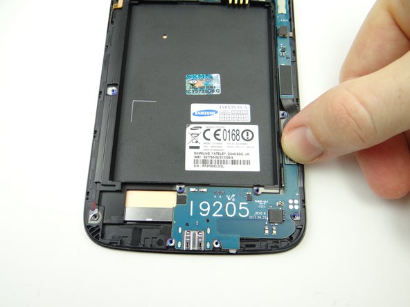
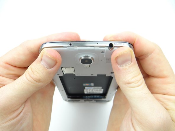
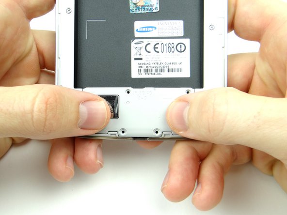
Picture 3: Carefully work your way around the corner to release clips holding the mid-frame.
-
-
-
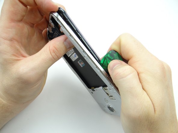
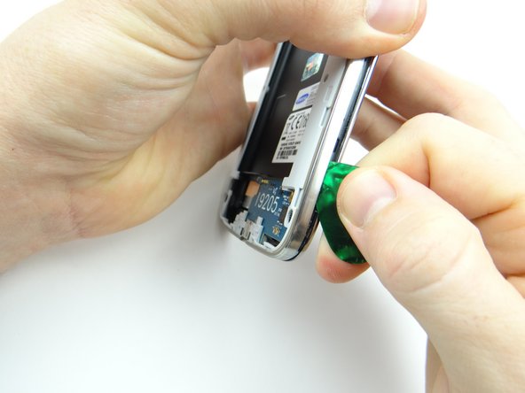
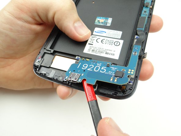
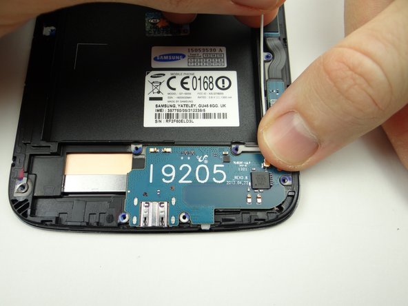
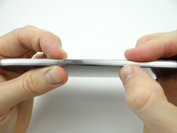
Picture 1: Move up the side of the mid-frame. Remove the guitar pick before you reach the power button.
-
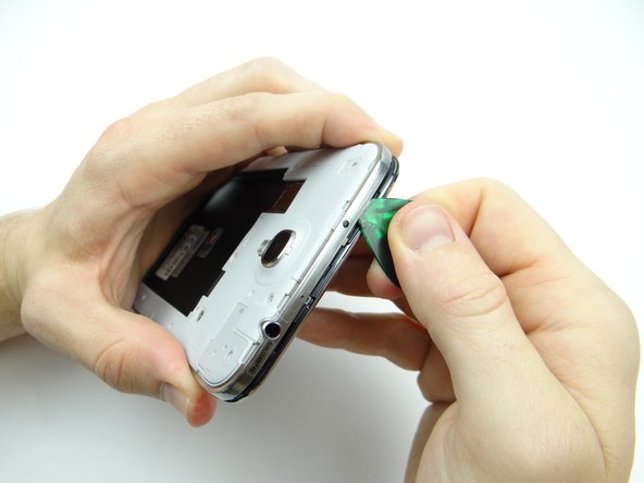
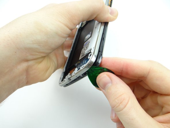
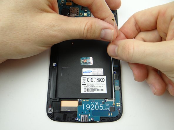
Picture 2: Gently tug on the mid-frame with one hand to create space, then reinsert the guitar pick in the corner above the power button with the opposite hand.
-
Picture 3: Release the clips along the top edge of the mid-frame.
-
-
-
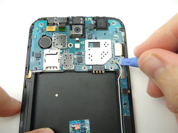
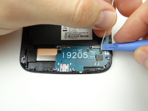
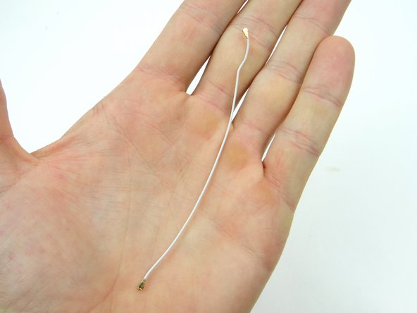
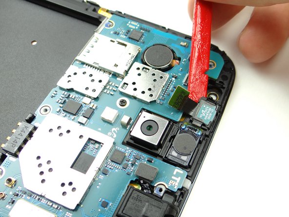
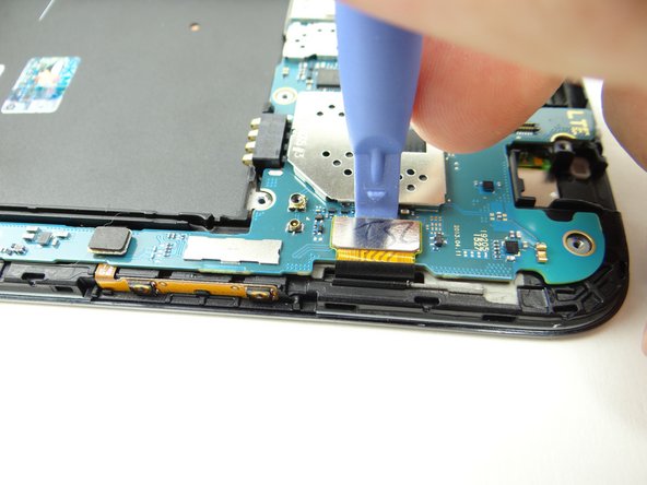
Disconnect the cellular antenna:
-
Use blue pry tool to disconnect top.
-
Unthread antenna.
-
-
-
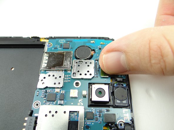
Picture 1: Remove 2.4 mm #00 Phillips screw from shield (covering front-facing camera and infrared sensor). Place in SLOT 2.
-
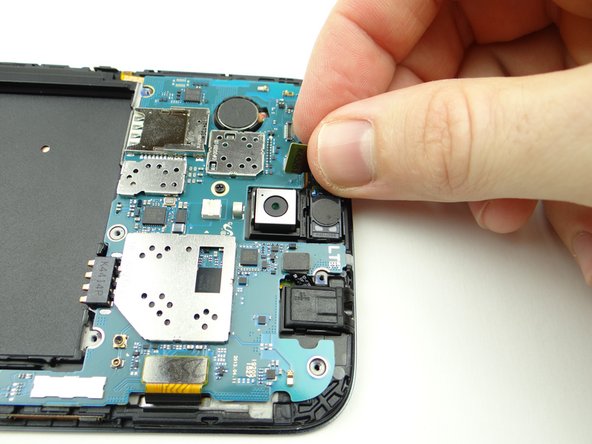
Picture 2: Avoid contact with the infrared sensor as you remove the shield covering the front camera & speaker:
-
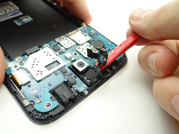
Picture 3: Wedge one prong of the curved-tip tweezers under the shield as shown.
-
-
-
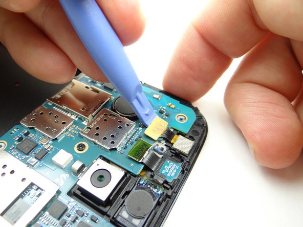
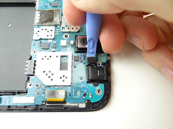
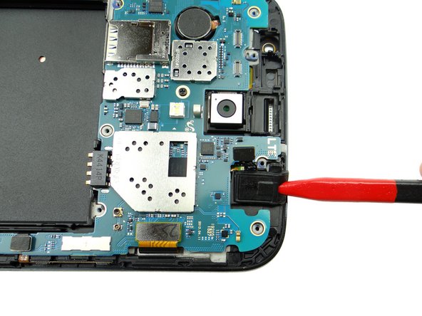
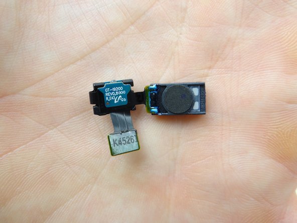
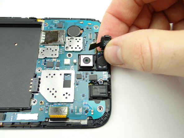
Disconnect infrared sensor / earpiece speaker assembly with blue pry tool.
-
Wedge the flat end of the spudger under the infrared sensor and pry up slightly.
-
-
-
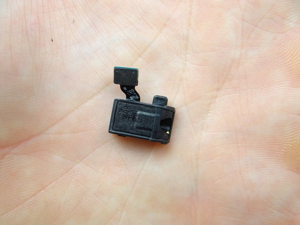
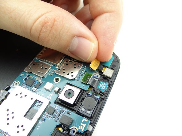
Disconnect the headphone jack.
-
Use the pointed tip of the spudger to lift the headphone jack free.
-
Place headphone jack in COMPARTMENT C.
-
-
-
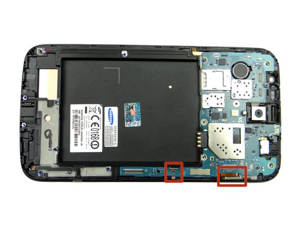
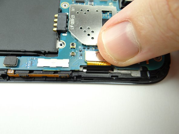
Picture 1: Remove one 2.4 mm #00 Phillips screw. Place in SLOT 2.
-
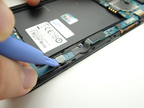
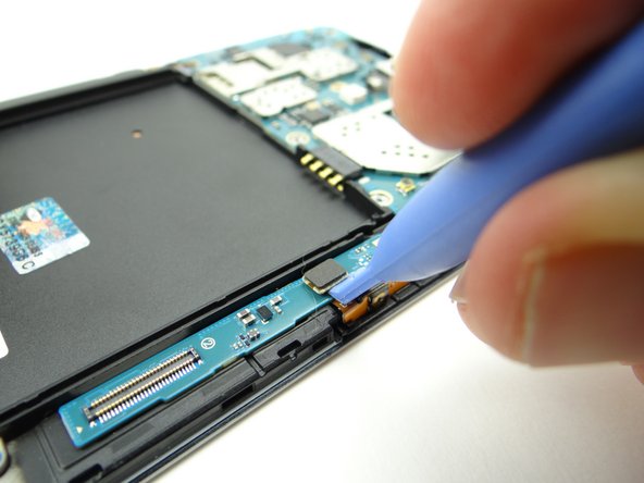
Picture 2: Disconnect display cable.
-
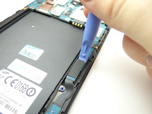
Picture 3: Disconnect volume rocker cable.
-
-
-
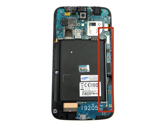
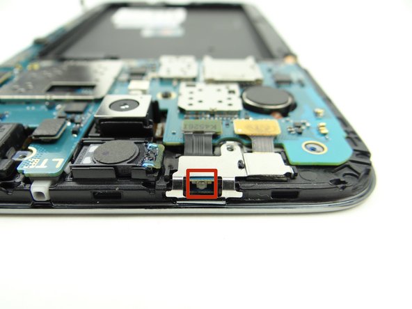
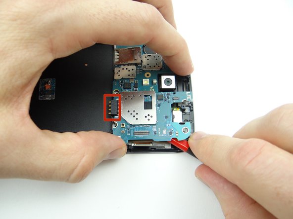
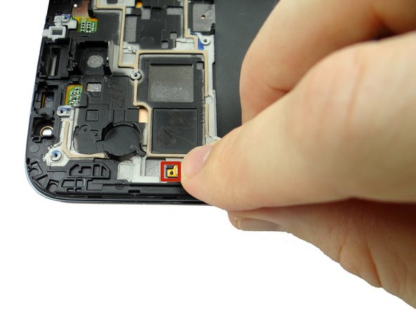
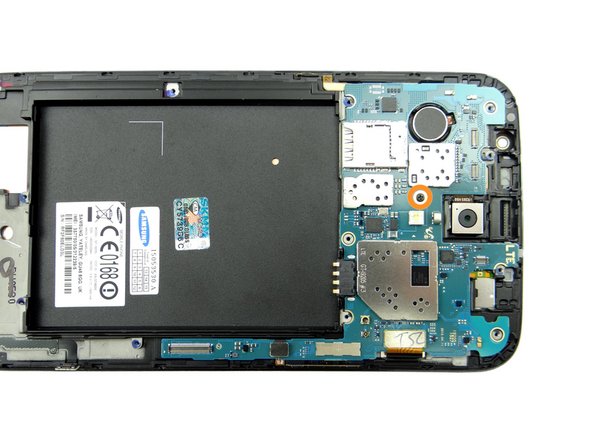
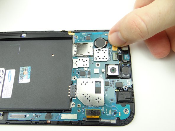
There is a small amount of adhesive under the battery contact (red square in Picture 1):
-
Picture 1: Wedge flat end of the spudger under the corner of the logic board. Slowly twist the spudger to free the adhesive under the battery contact.
-
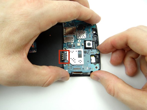
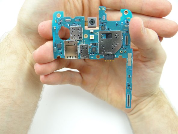
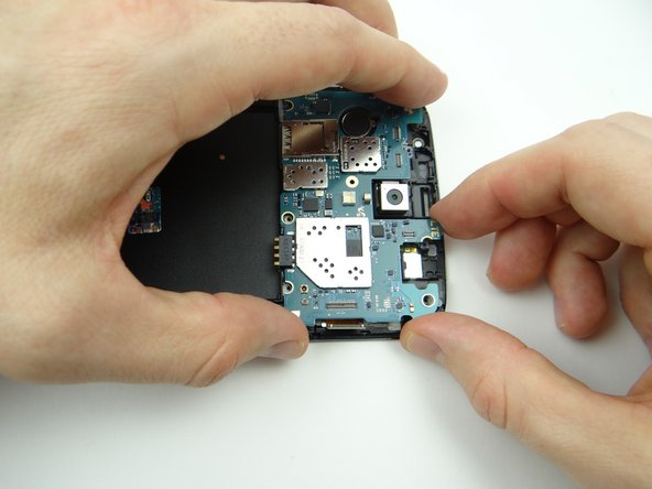
Picture 2: Use both hands to gently guide the logic board away from the front panel.
-
Place logic board in ZONE IV.
-
-
-
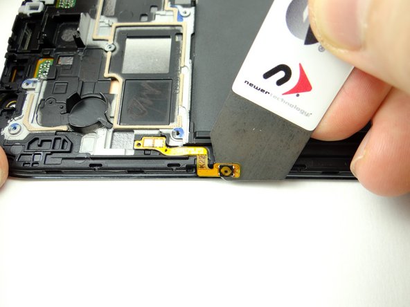
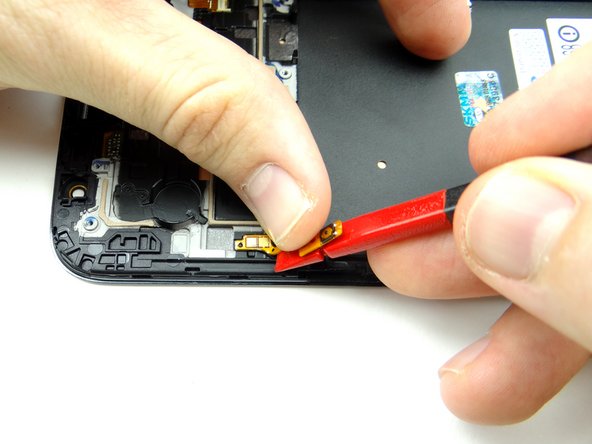
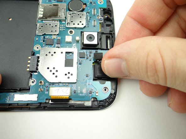
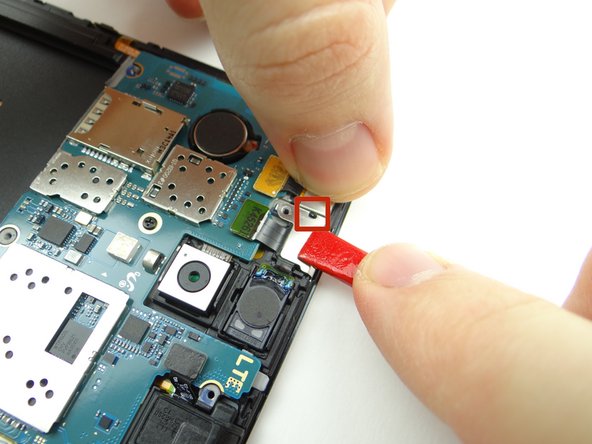
Read through this entire step before performing it if you intend to reuse the power button cable:
-
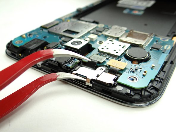
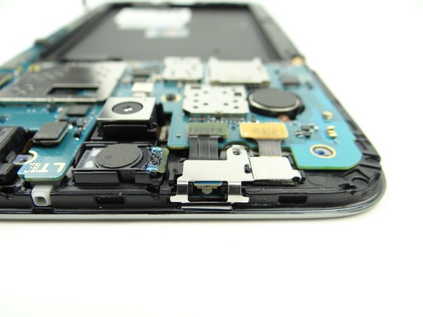
Picture 1: Use the iSesamo to separate the power button from the front panel.
-
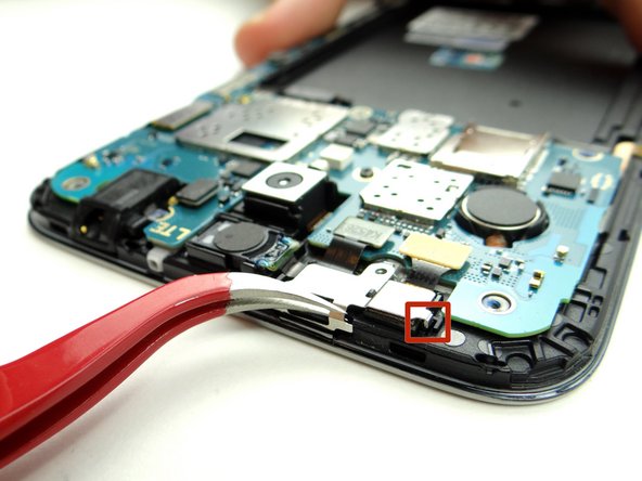
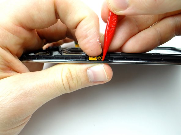
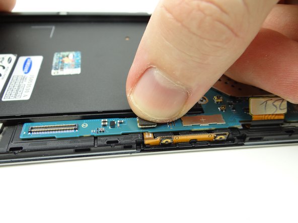
Picture 2: Wedge the spudger under the power button. Lift the power button while using your thumb on the opposite hand to help control the movement. Stop when you reach the contact pad.
-
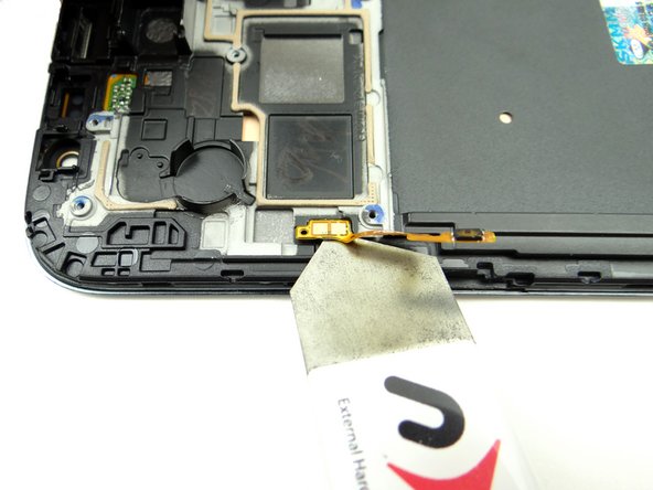
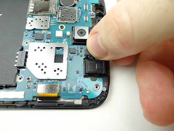
Picture 3: Use the iSesamo to lift the power button contact pad away from the front panel.
-
-
-
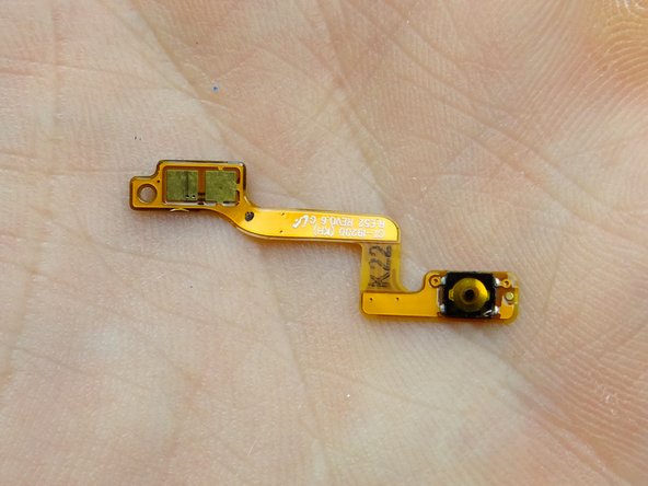
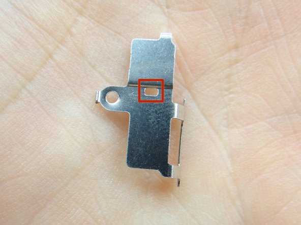
Replace power button from COMPARTMENT E:
-
Push firmly into place against the front panel wall.
-
Seat the opening on the cable over the tab on the front panel.
-
-
-
From ZONE IV seat the logic board:
-
Make sure the display cable and volume cable aren't trapped underneath.
-
-
-
Seat headphone jack from COMPARTMENT C, then:
-
Connect headphone jack cable.
-
-
-
From COMPARTMENT C seat earpiece speaker / infrared sensor assembly:
-
Seat earpiece speaker first.
-
Then seat infrared sensor and connect the cable to the logic board.
-
-
-
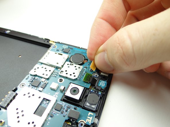
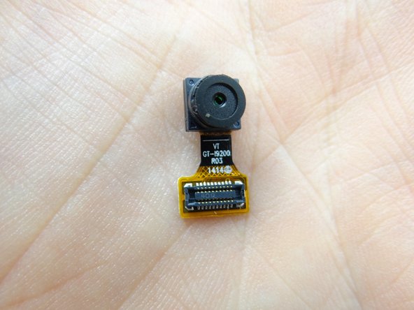
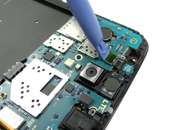
Replace front-facing camera from COMPARTMENT C:
-
Seat camera.
-
Connect camera cable.
-
-
-
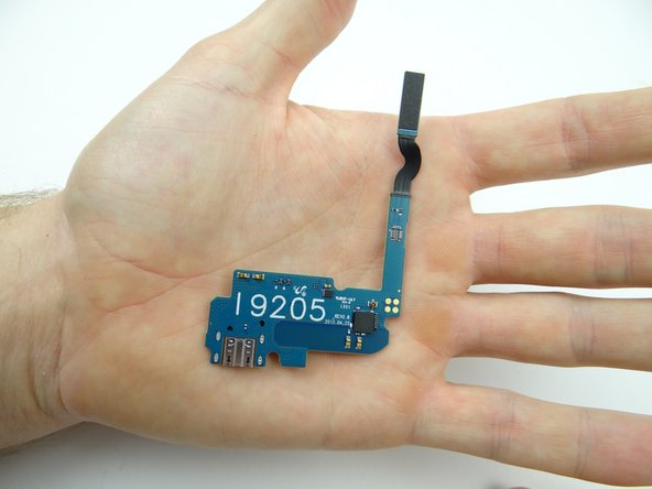
Seat charging port from ZONE III:
-
Connect charging port cable to main logic board.
-
Connect soft keys cable to charging port daughter board.
-
-
-
From ZONE V, seat the mid-frame on the phone:
-
Line up the mid-frame, then:
-
Snap the bottom edge in place first, pushing down on either side of the charging port.
-
-
-
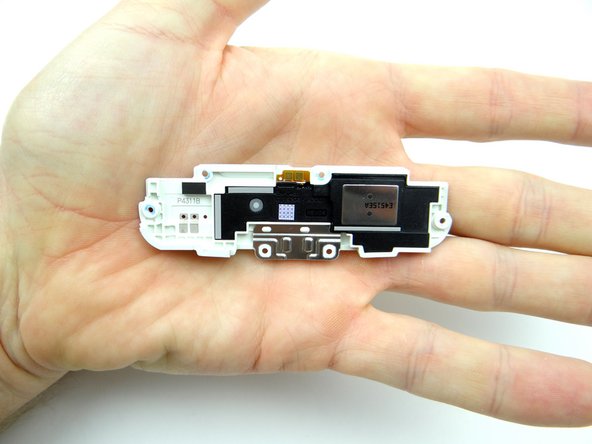
Replace loudspeaker assembly from ZONE I:
-
Line it up then snap it into place.
-