Parts
No parts specified.
-
-
Before disassembling the iPhone, thoroughly wash and dry your hands.
-
Make sure handset is powered off.
-
Place the handset in your non-dominant hand. Remove two Pentalobe screws near charging port with special 5-point Pentalobe screwdriver. Place screws in SLOT 1.
-
Gently slide battery cover upwards. Pull battery cover away from iPhone. Place battery cover in ZONE I.
-
-
-
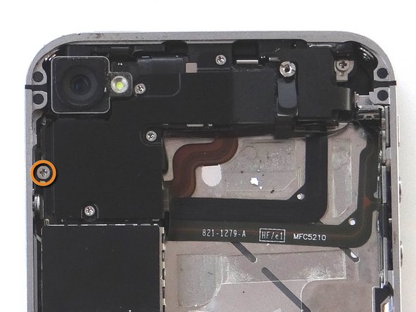
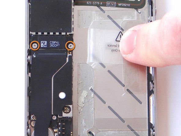
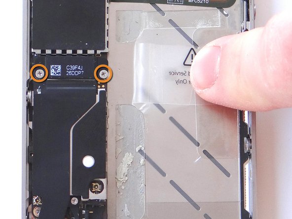
Remove the 1.5 mm Phillips screw from battery connector cable (circled in orange). Place screw in SLOT 2.
-
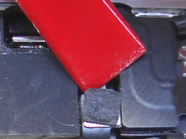
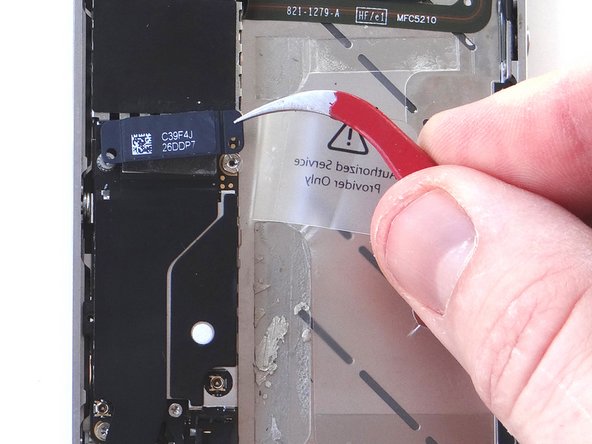
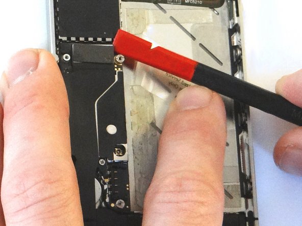
Use the flat edge of the Black Spudger (tip is painted red for better illustration) to gently pry the battery connector up from its socket on the logic board, top to bottom.
-
-
-
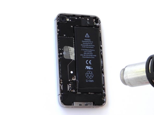
Apply low-level heat (100* Celcius or less) to edges of battery for 60 seconds to loosen the adhesive securing the battery to the iPhone.
-
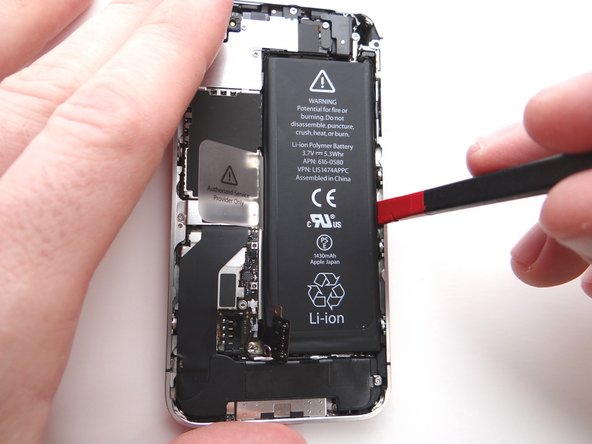
Wedge right-side of the battery up with the Black Spudger to free battery from adhesive securing it to Mid-Frame.
-
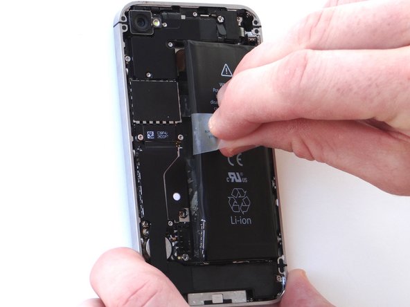
Grab battery removal tab and gently pull tab away from phone, taking care not to bend or warp the battery as you pull (you may have to use the spudger to help wedge it up). Apply more heat in 30 second increments, if needed.
-
Remove the battery and place in ZONE II.
-
-
-
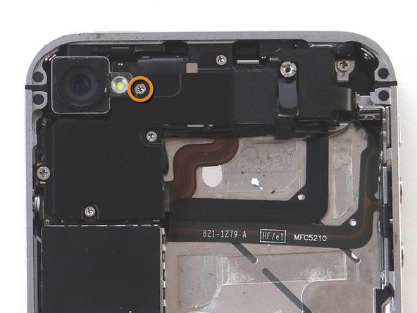
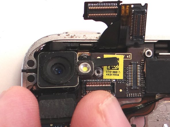
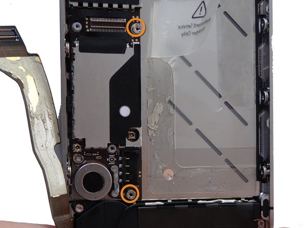
Remove five Phillips screws from the Cable Shield surrounding the camera. Use fine point tweezers to remove them if the screwdriver won't hold them:
-
Picture 1: Remove one 2.4 mm Phillips screw. Place in Sandbox SLOT 3.
-
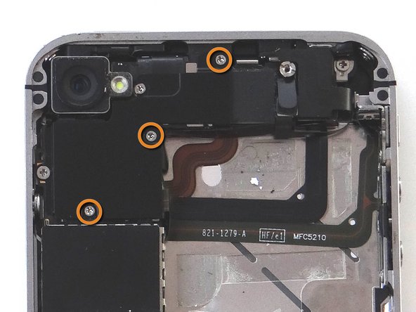
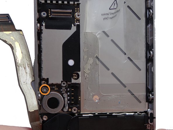
Picture 2: Remove one 1.5 mm Phillips screw. Place in SLOT 4.
-
Picture 3: Remove three 1.3 mm Phillips screws. Place in SLOT 5.
-
-
-
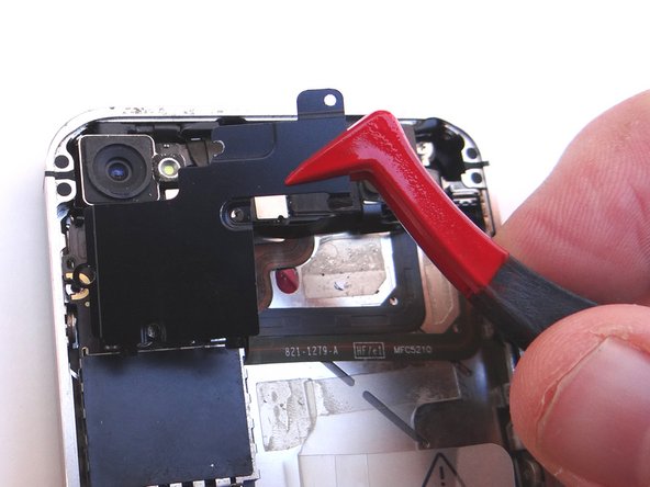
Before performing this step, make sure the Black Spudger is wedged under the lip of the cable. Also, be careful not to break any components off the surrounding area on the logic board:
-
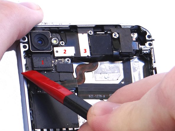
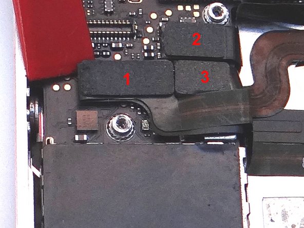
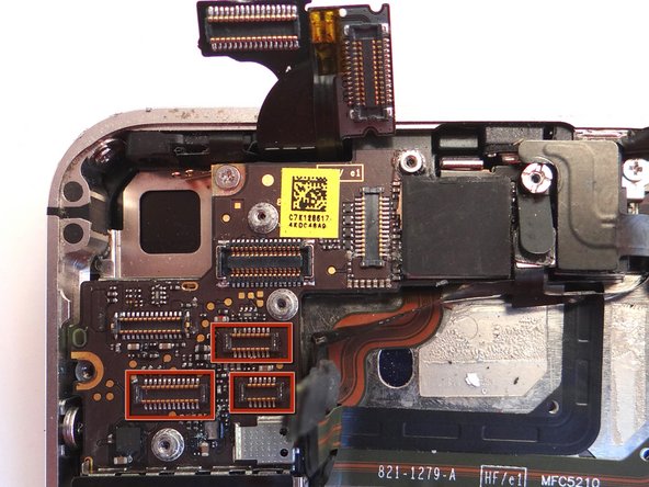
Use the flat end of the Black Spudger to gently pry three cables free from their sockets on the logic board.
-
Lift camera away from iPhone. Place in COMPARTMENT B.
-
-
-
Release three cables just below the camera slot using the Black Spudger to gently lift the connectors up and out of the sockets.
-
-
-
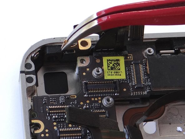
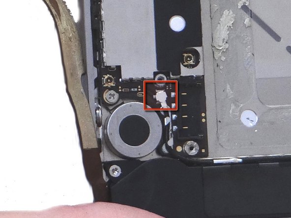
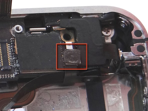
Picture 1: There may be a small piece of black electrical tape covering the pictured screw. If it's there use Plastic Tweezers to remove and discard it.
-
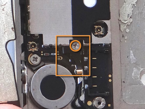
Remove 2.5 mm Phillips screw securing Gold Grounding Clip to logic board near rear camera opening. Place screw in SLOT 6.
-
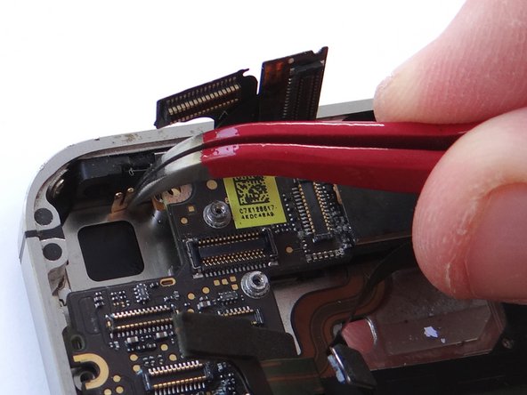
Remove Gold Grounding Clip with curved tip tweezers. Lift straight up and be careful not to scratch the logic board with the tweezers.
-
Place clip in SLOT 6 with Phillips screw.
-
-
-
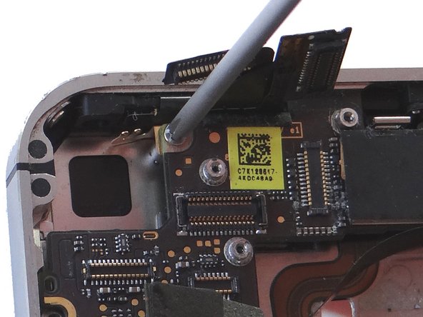
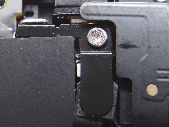
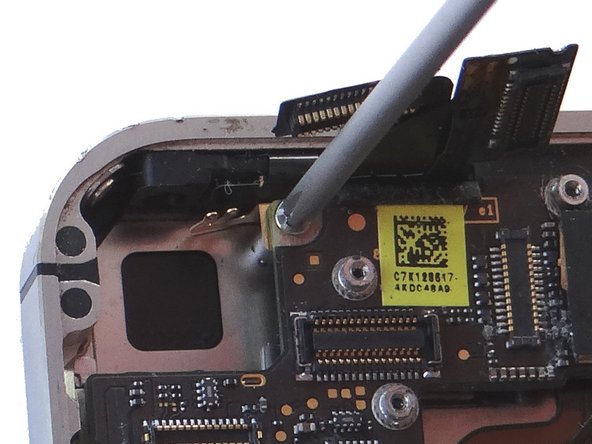
Remove Antenna Shield: Older iPhones are held in place with a Standoff Screw and will NOT have a Phillips screw on top.
-
Picture 1: Remove the 1.5 mm Phillips Screw holding the Antenna Shield. Place in SLOT 7.
-
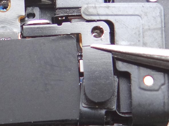
Picture 2: Remove the Antenna Shield with your fingers or Fine Point Tweezers. Place with the Phillips screw in SLOT 7.
-
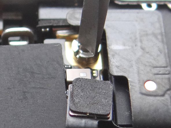
Picture 3: Use a Small Flathead Screwdriver to remove the 4.8 mm Standoff Screw near the headphone jack. Place standoff in SLOT 7 with the Phillips screw and Antenna Shield.
-
-
-
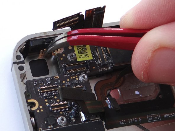
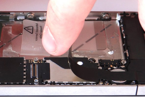
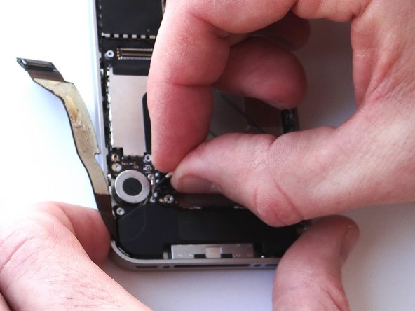
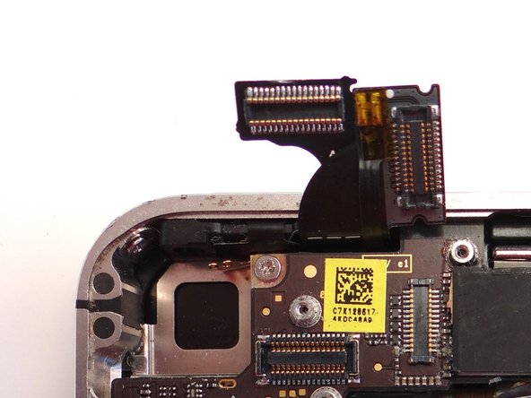
Picture 1: Place flat end of spudger under upper-right corner of the charging port assembly cable. Gently twist your hand clockwise releasing the cable from its socket on the logic board.
-
Picture 2: The charging port assembly cable is adhered to the logic board – gently peel it free from the logic board, working top to bottom until cable is free of logic board. Be cautious as this cable is very fragile.
-
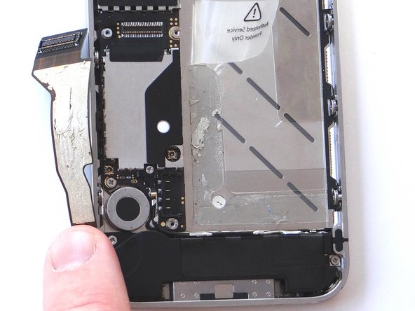
Picture 3: Fold the cable to the left.
-
-
-
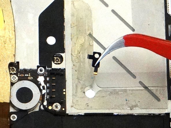
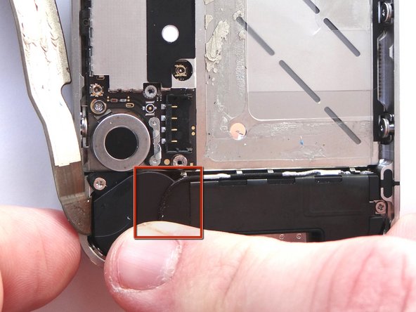
Picture 1: Place Black Spudger under antenna. Gently lift to release antenna from its socket on the logic board.
-
Picture 2: Use your fingers to de-route the cellular antenna cable out from under the metal clips attached to the logic board. First pull cable right, then left.
-
Picture 3: Fold the antenna down so it's out of the way.
-
-
-
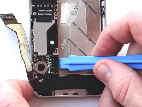
Picture 1: Using the blue pry tool, carefully lift the logic board just high enough to pinch it with your left thumb and index finger.
-
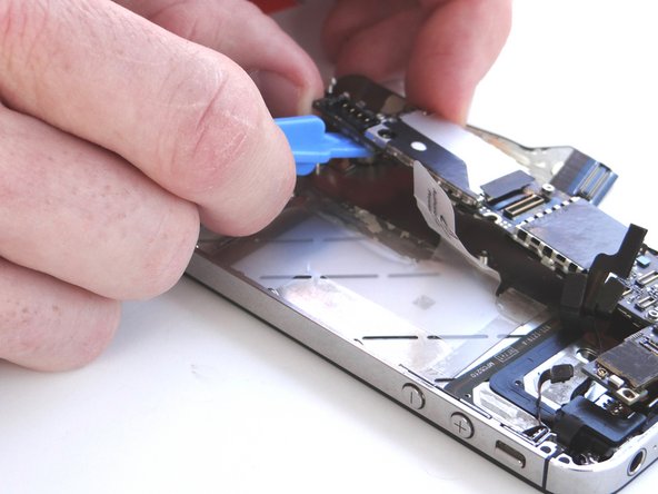
Picture 2: Once you have a good grip on the logic board, use your right hand to brush away cables near the top while pulling the logic board towards you until it is free from the mid-frame. Place in ZONE III.
-
-
-
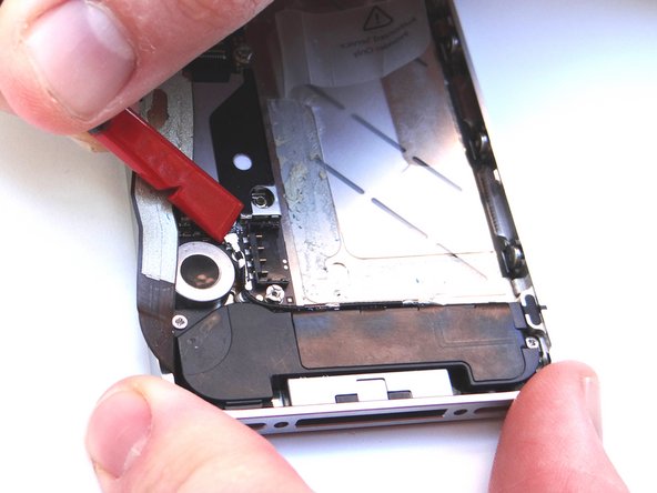
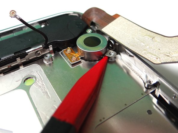
Picture 1: Wedge the pointed tip of the Black Spudger under the lip of the vibrator. Gently lift to loosen the adhesive holding the vibrator to the mid-frame.
-
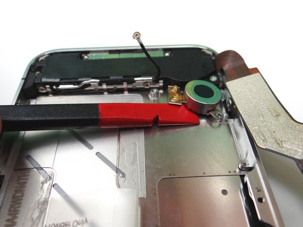
Picture 2: Wedge the flat end of the spudger (you may prefer to use the iSesamo) under the vibrator until it's free. Place it in COMPARTMENT C.
-
-
-
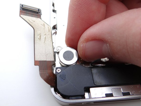
Use your fingers to replace the vibrator from COMPARTMENT C.
-
Make sure the mounting tab on the vibrator lines up with the screw slot on the mid-frame.
-
-
-
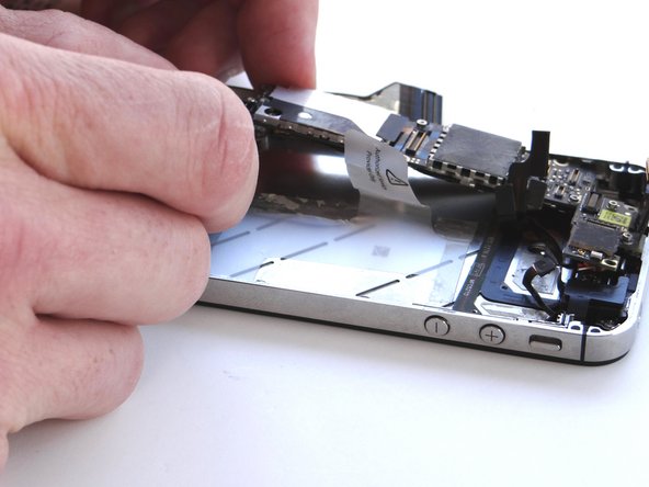
Picture 1: Grab the logic board from ZONE III and carefully position the top edge into the mid-frame. Make sure the top edge is below the protruding tab on the mid-frame.
-
Push the logic board down into its position on the mid-frame.
-
Make sure no cables get trapped under the logic board while re-installing it.
-
Picture 2: Use a small flathead screwdriver to replace the two 3.6 mm standoffs (on the right) from SLOT 11.
-
Picture 3: Replace the 3.4 mm Phillips screw (on the left) near the vibrator motor with the screw from SLOT 10.
-
-
-
Replace camera from COMPARTMENT B. Push connector into socket on logic board.
-
Reconnect the digitizer and LCD cables (sitting upright in the picture).
-
-
-
Reinsert the battery from ZONE II. Push battery connector into its socket the logic board.
-
Use the screw from SLOT 2 to secure the battery.
-
-
-
Grab battery cover from ZONE I.
-
Place battery cover 2 mm above the bottom of the iPhone and slide it down to lock it in place.
-
Secure the battery cover with two Pentalobe screws from SLOT 1.
-