-
-
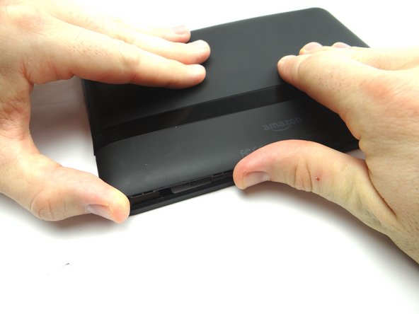
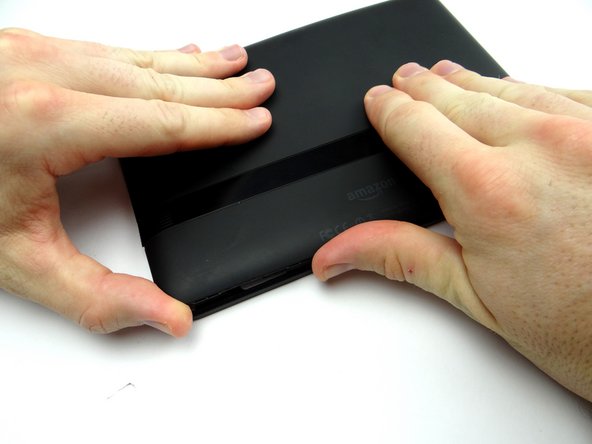
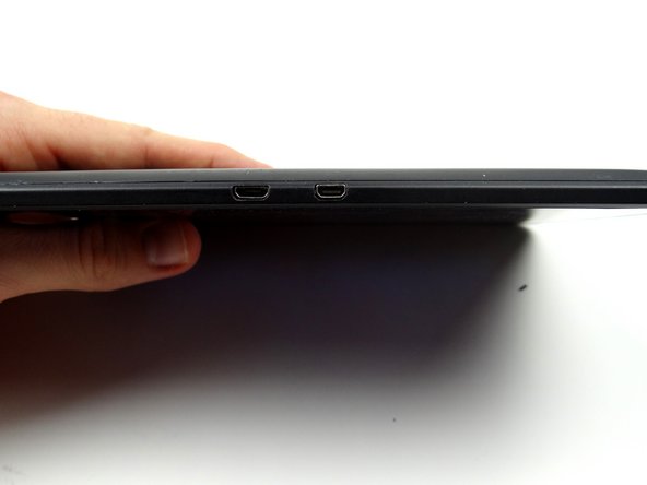
Picture 1: Insert the blue pry tool between the front panel and battery cover, with the the tip face down, an inch left of the charging port. Pop up the cover just enough to reinsert the blue pry tool face up.
-
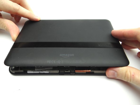
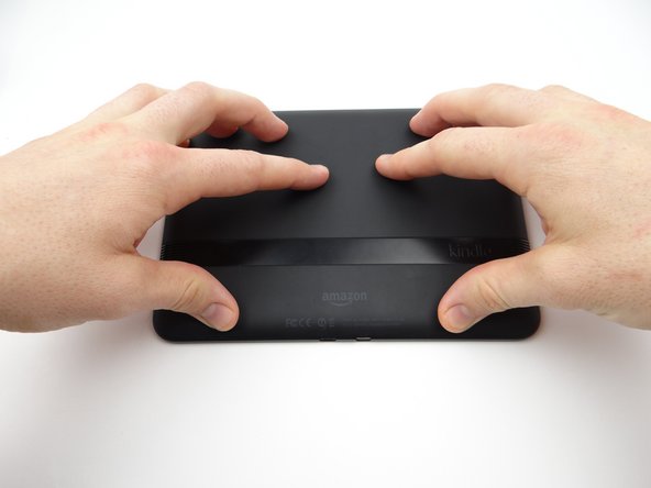
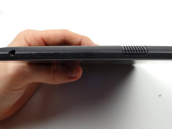
Pictures 2 & 3: Insert the blue pry tool face up an inch left of the charging port. Twist until you can grab the battery cover with your fingers.
-
-
-
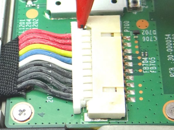
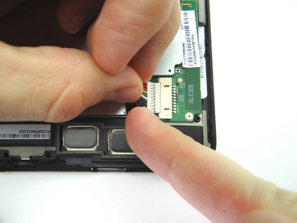
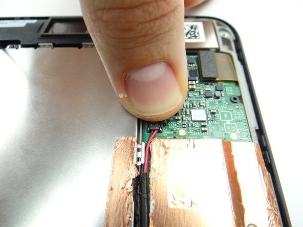
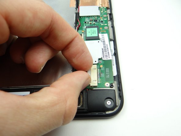
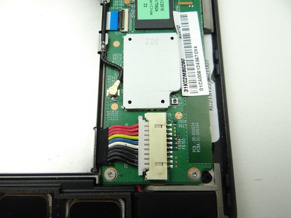
The battery connector is stiff and fragile:
-
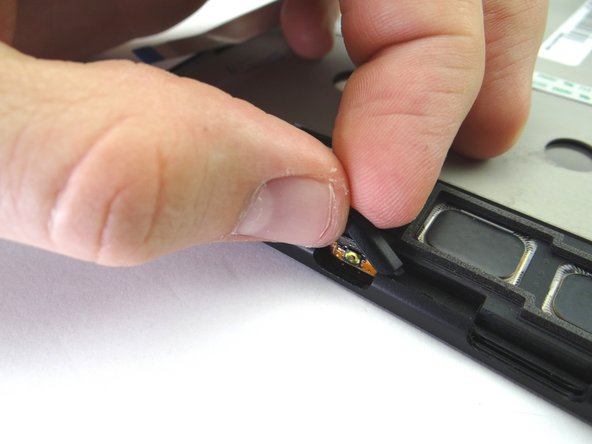
Picture 1: Use the pointed end of the spudger to push back the top of the battery connector slightly.
-
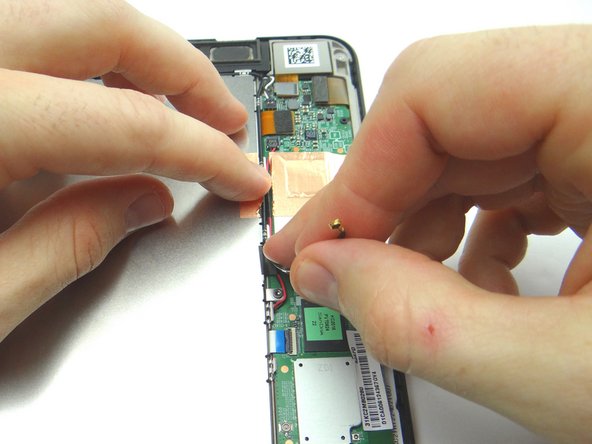
Picture 2: Use your finger to put mild tension at the top of the connector while using the spudger to push back the bottom of the connector.
-
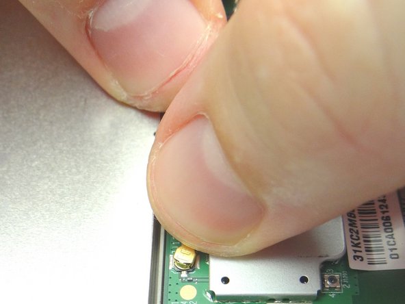
Picture 3: Finish removing the connector with your fingers.
-
-
-
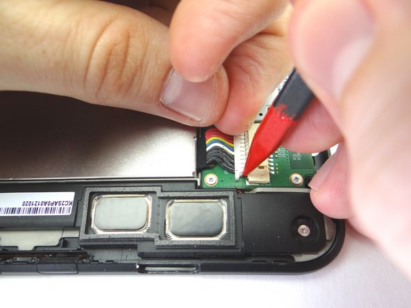
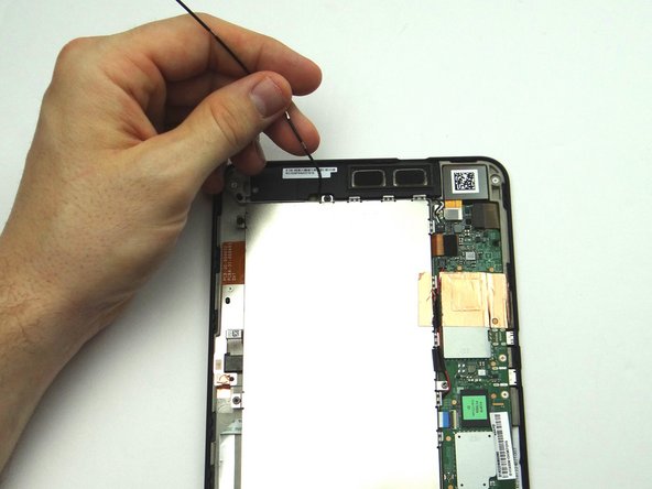
With the pointed end of the spudger, cut through the copper tape covering cables.
-
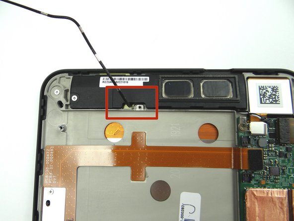
Use plastic tweezers to remove the Kapton tape covering the top speaker connector.
-
-
-
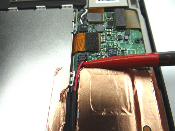
Picture 1: Wedge the pointed end of the spudger under lower speaker cable connector and lift straight up.
-
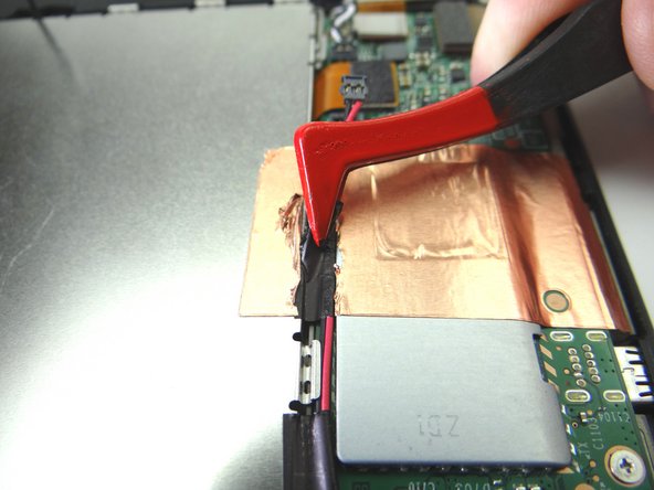
Picture 2: Use plastic tweezers to peel up the black electrical tape covering the speaker cable, without removing it, to free the cable.
-
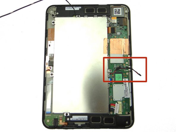
Picture 3: Move the speaker cable out of the way of the battery.
-
-
-
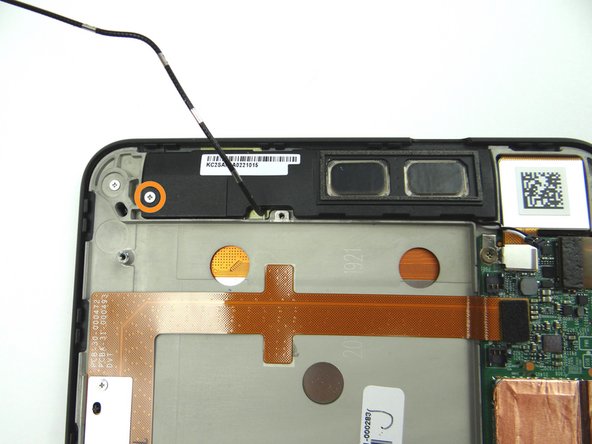
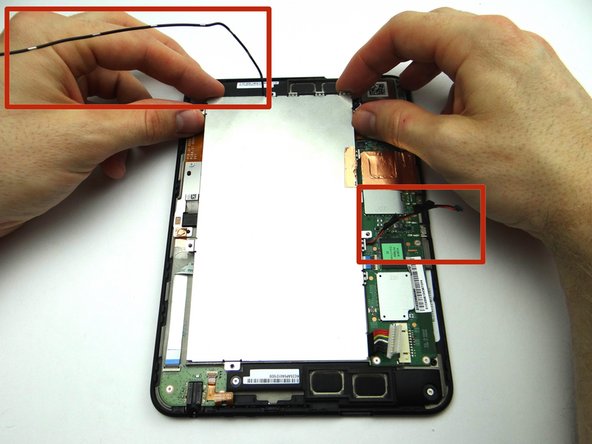
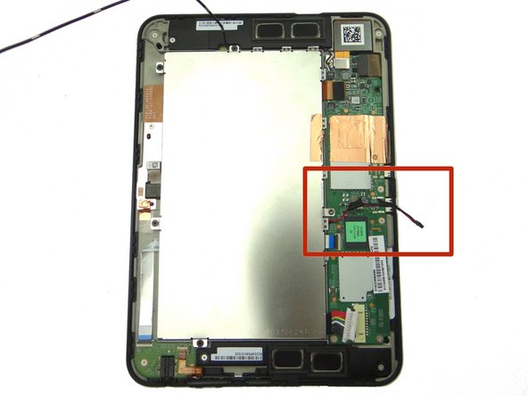
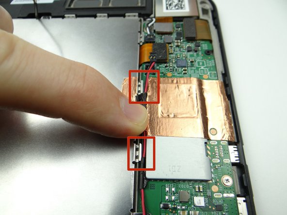
Pictures 1 & 2: Disconnect top speaker cable.
-
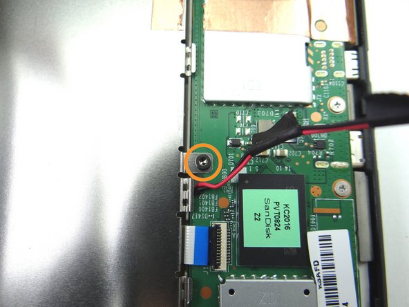
Picture 3: Remove one 3.1 mm #00 Phillips screw. Place in SLOT 3.
-
-
-
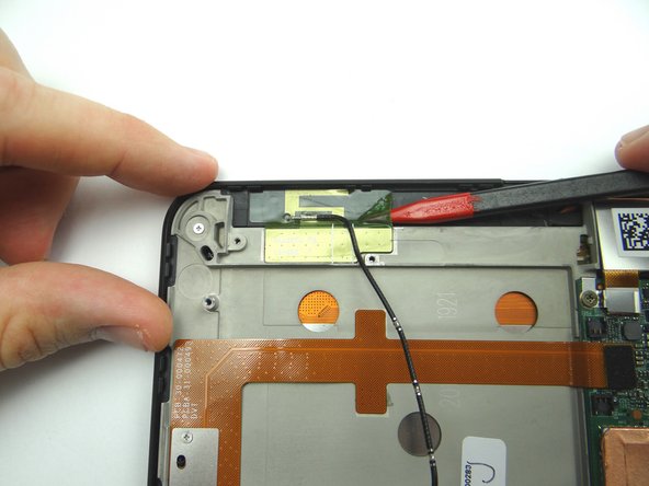
Use pointed end of spudger to peel up corner of antenna gel tape.
-
The gel tape is durable. The spudger won't damage it so long as you're careful.
-
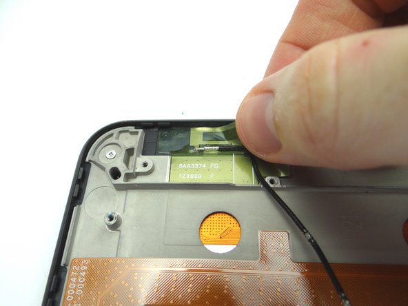
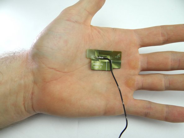
Continue peeling up antenna with your fingers.
-
Place in COMPARTMENT C.
-
-
-
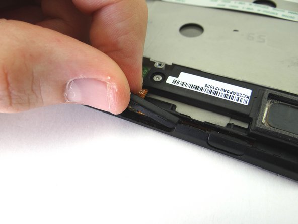
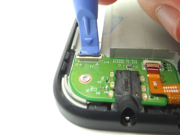
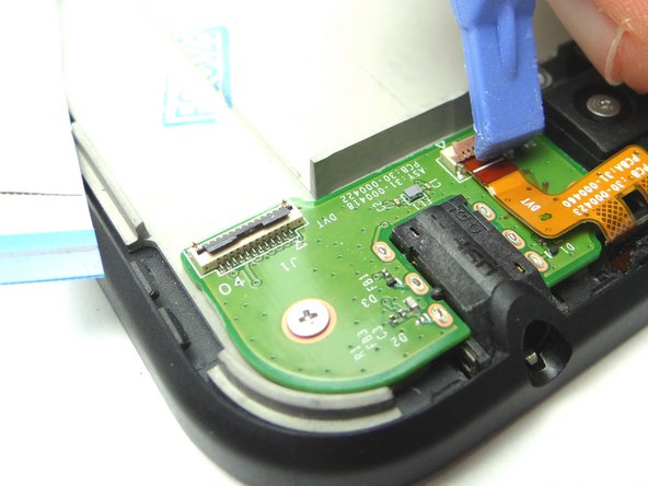
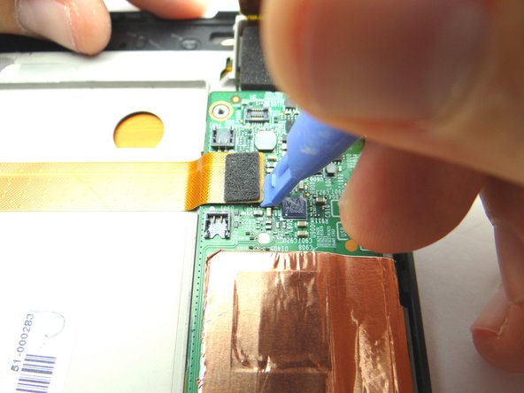
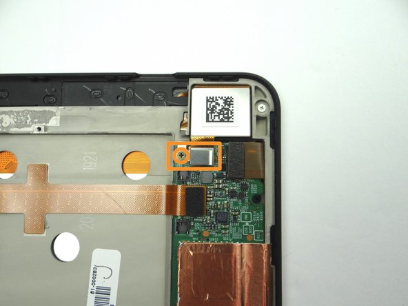
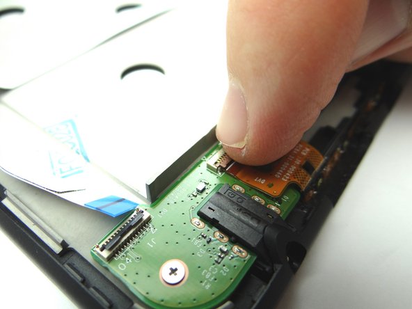
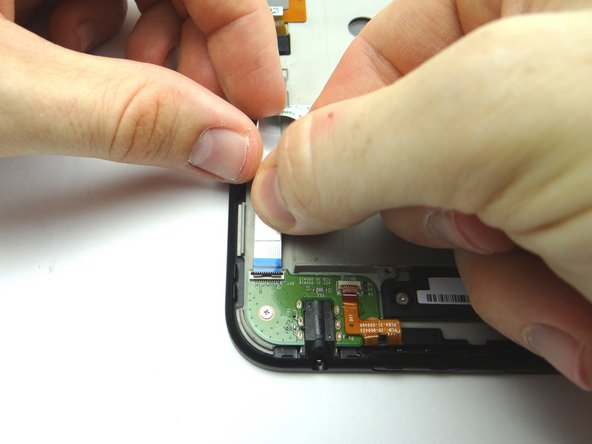
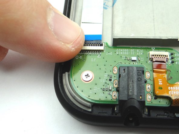
Picture 1: Use blue pry tool to open ZIF connector.
-
Picture 2: Remove headphone jack cable with your fingers.
-
-
-
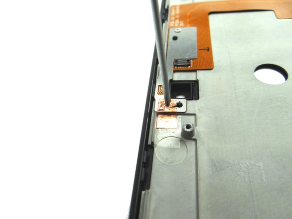
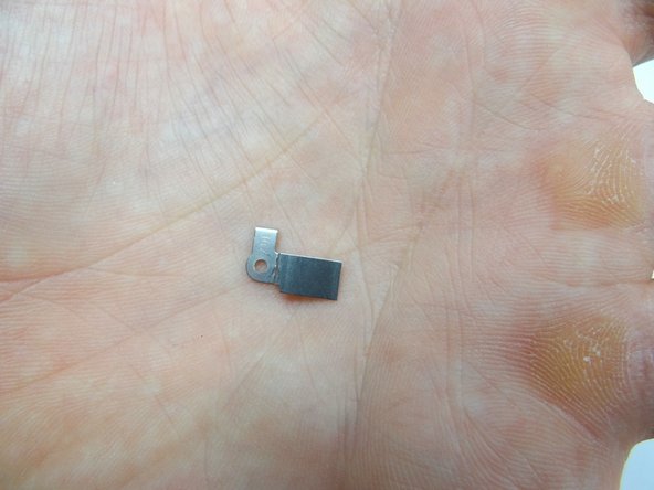
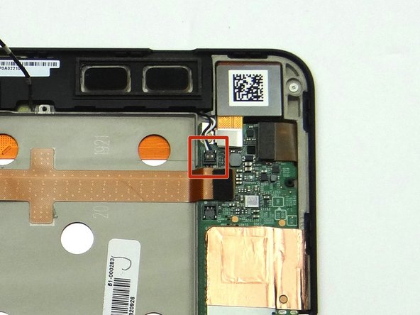
Pictures 1 & 2: Remove 1.8 mm #00 Phillips screw. Place in SLOT 5. Place the bracket held down by the screw in SLOT 5 too.
-
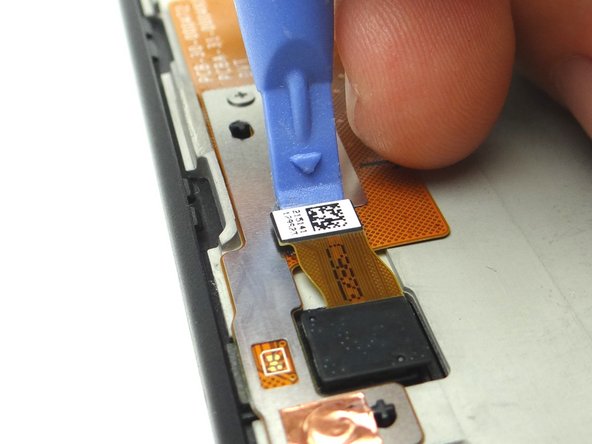
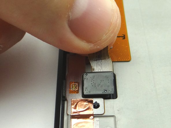
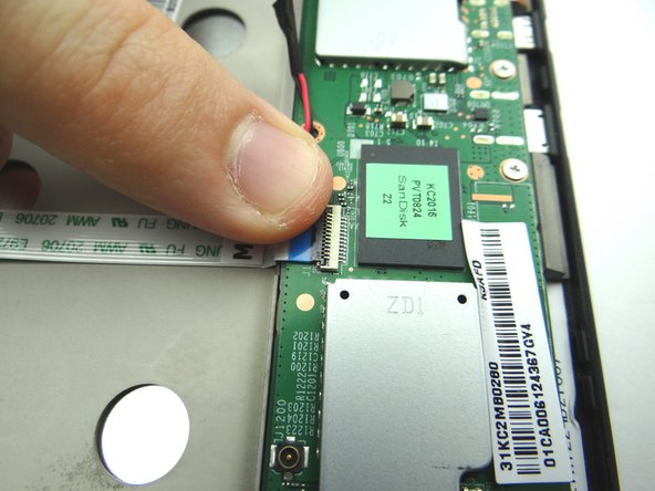
Picture 3: Disconnect digitizer cable.
-
-
-
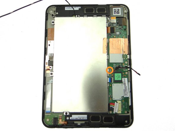
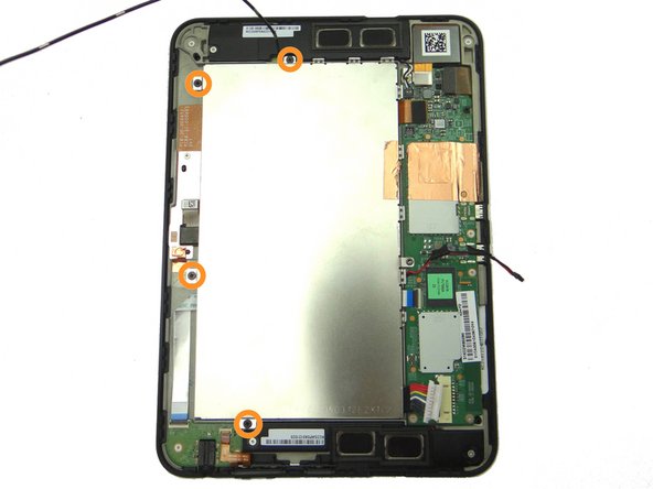
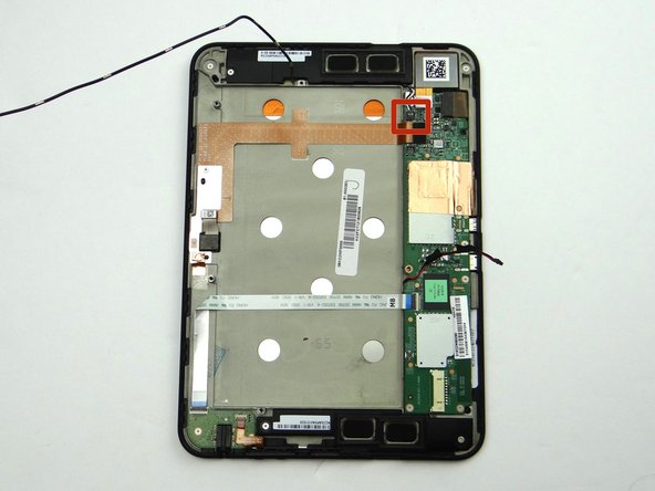
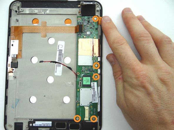
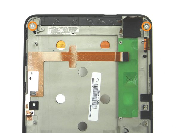
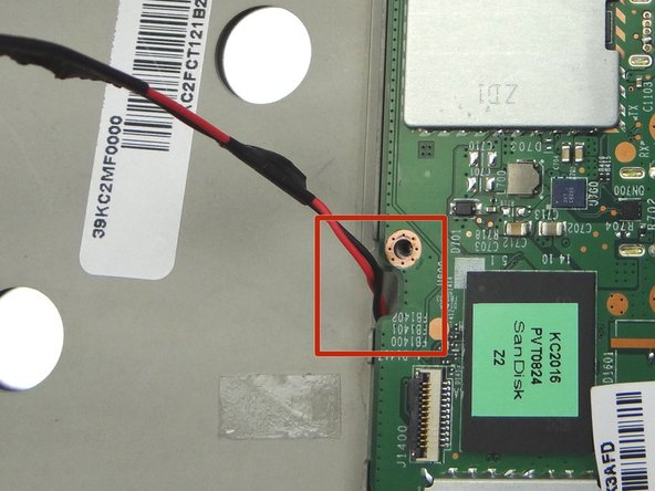
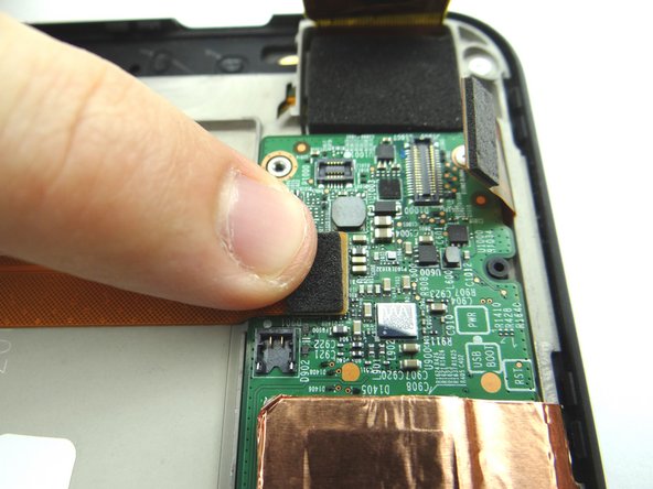
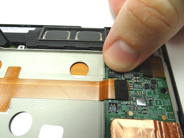
Picture 1: Remove five 3.2 mm #00 Phillips screws holding down logic board. (Note the hidden screw in the upper-right hand corner). Place in SLOT 6.
-
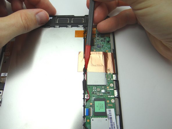
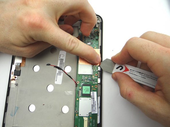
Picture 2: Peel up the corner of the copper tape with the iSesamo in one hand, while protecting the logic board from contact with the iSesamo tool with your pointer finger on the opposite hand.
-
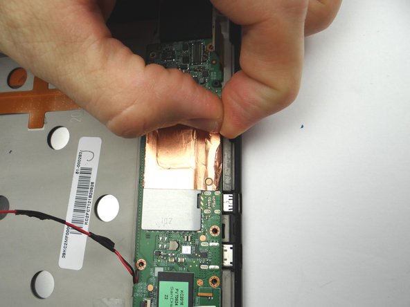
Picture 3: Continue peeling the tape up from the mid-plate with your fingers.
-
-
-
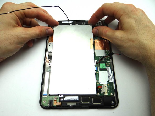
There should be minimal tension while removing the logic board:
-
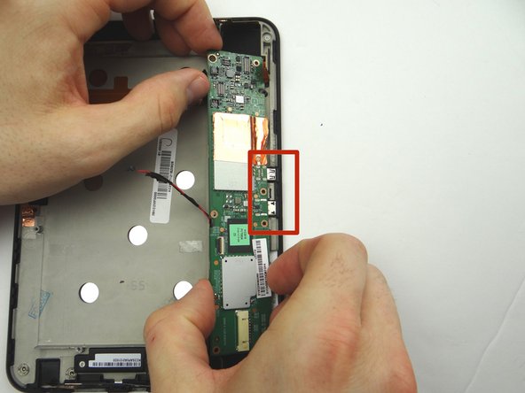
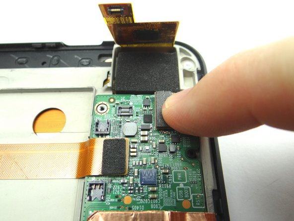
Picture 1: Lift the top of the logic board with the blue pry tool just enough to wedge your pointer finger underneath.
-
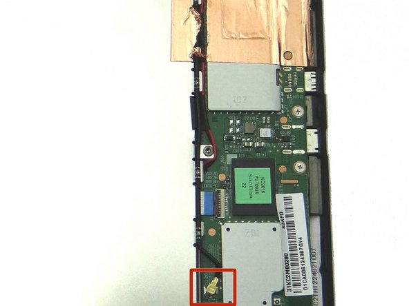
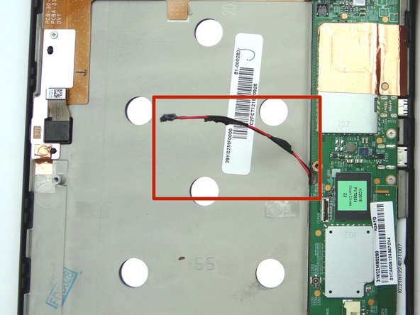
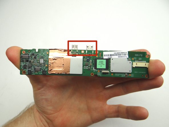
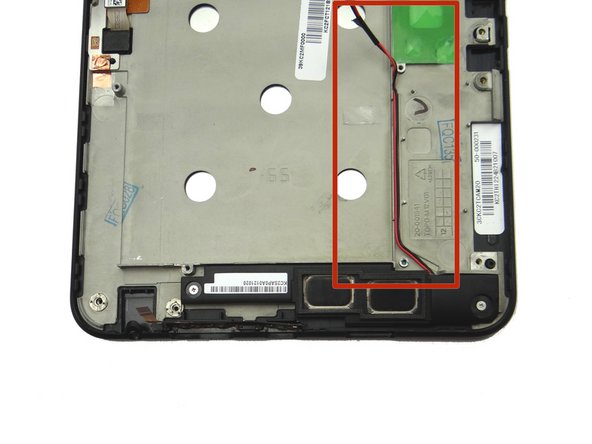
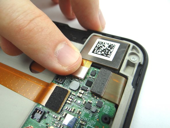
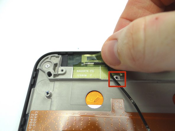
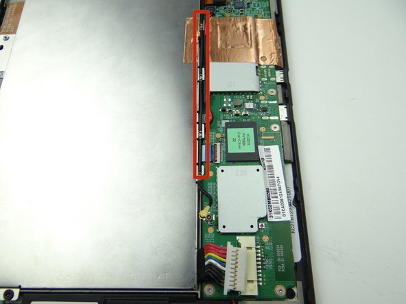
Picture 2: Grab the logic board with your fingers and carefully guide the charging port and HDMI port (red square) out of their sockets. Finish removing the logic board.
-
Picture 3: Shows the charging port and HDMI port (red square). Place logic board in ZONE V with battery and battery cover.
-
-
-
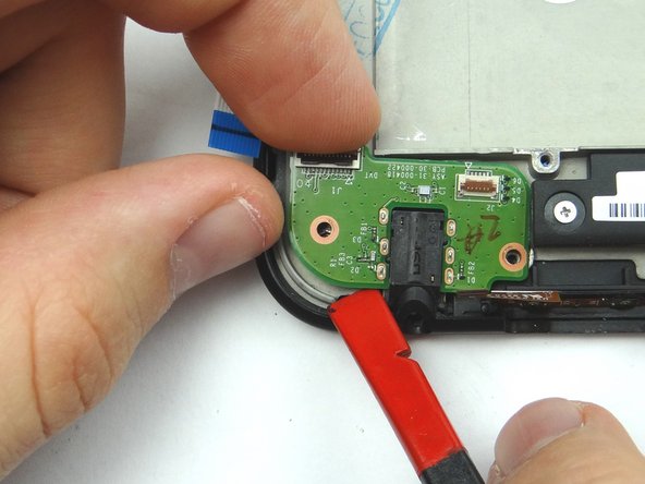
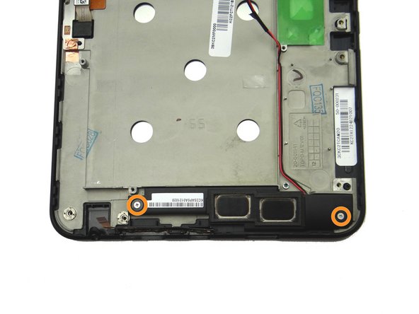
Remove two 3.1 mm #00 Phillips screw. Place in SLOT 7.
-
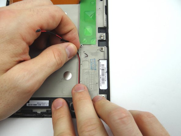
Peel up speaker cable.
-
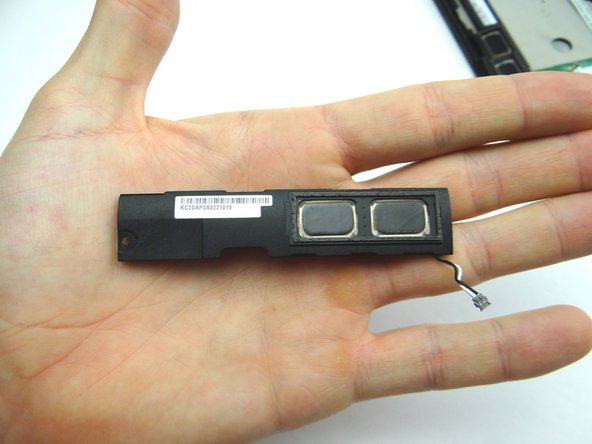
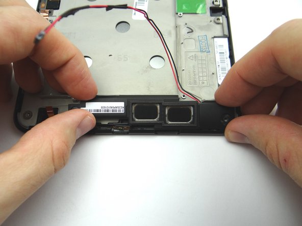
Remove lower speaker and place in ZONE II.
-
-
-
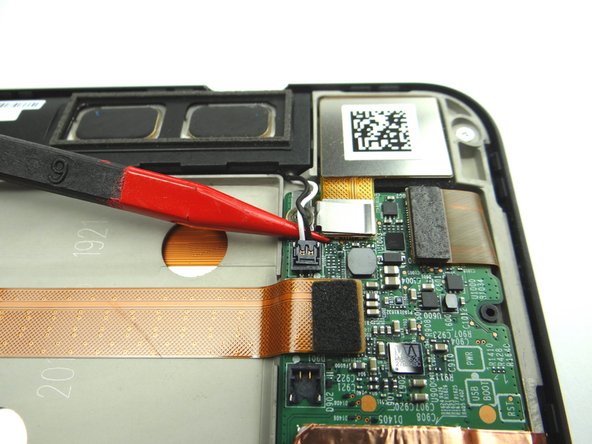
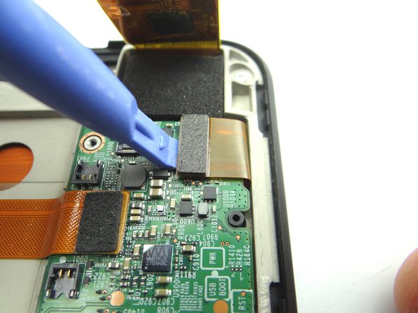
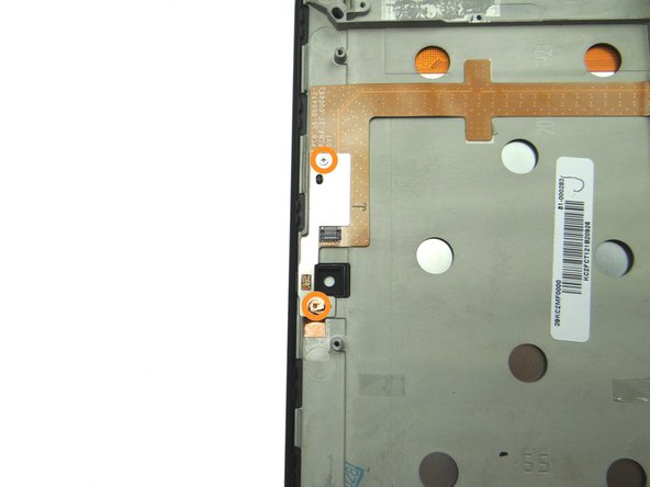
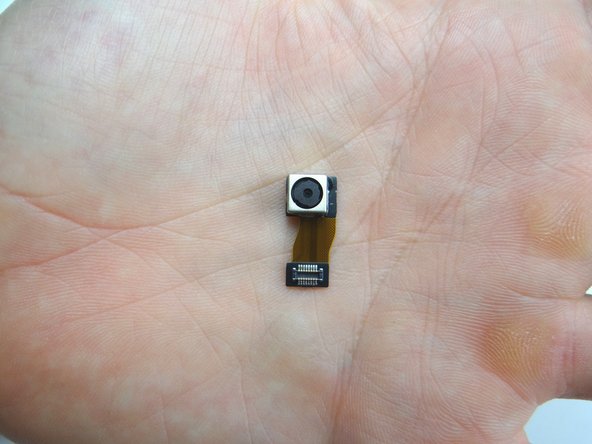
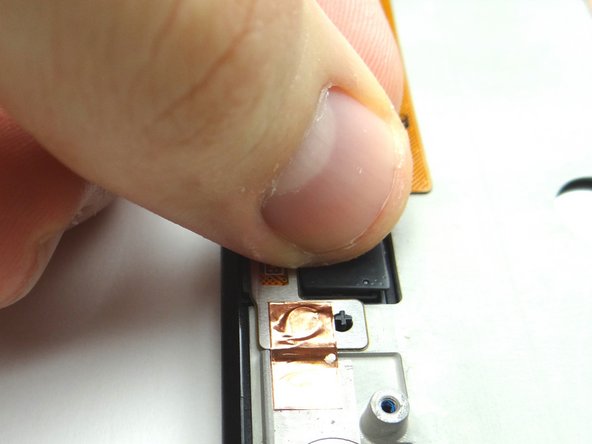
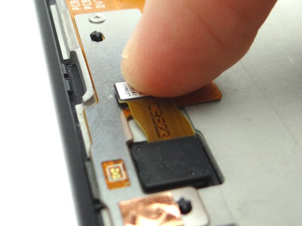
Use blue pry tool to disconnect the camera.
-
Remove it and place it in COMPARTMENT D.
-
-
-
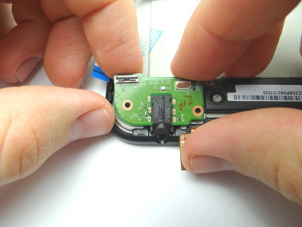
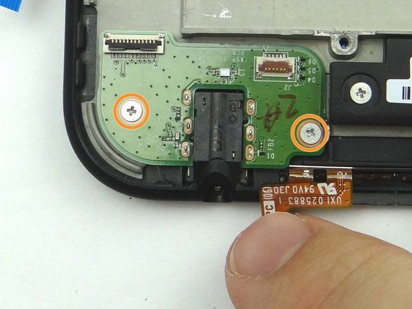
Picture 1: Remove two 3.1 mm #00 Phillips screws and place in SLOT 8.
-
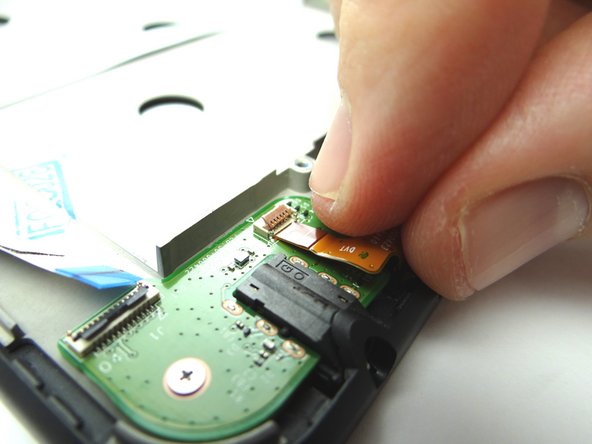
Pictures 2 & 3: Remove two 3.2 mm #00 Phillips screws and place in SLOT 9. The bottom screw is covered by copper tape - simply push the screwdriver through the tape.
-
-
-
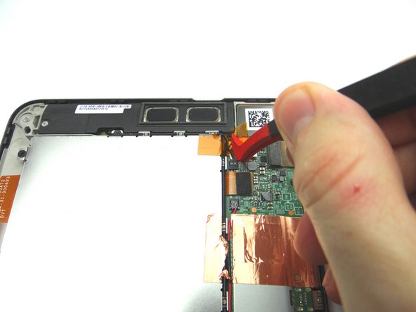
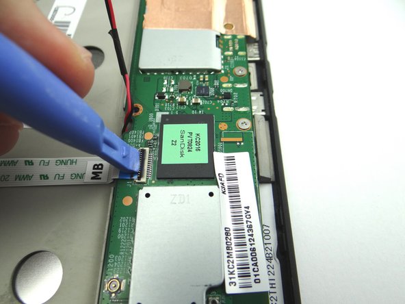
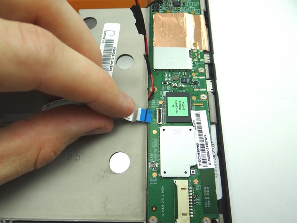
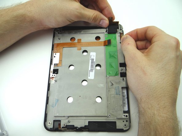
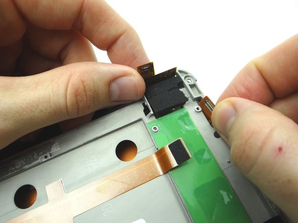
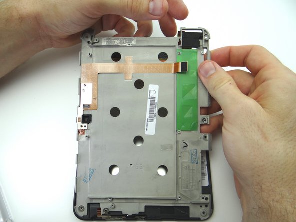
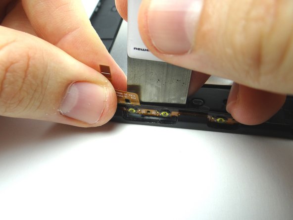
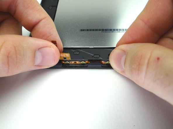
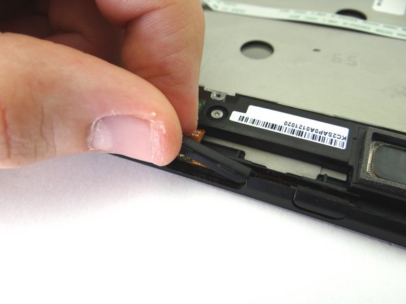
Use the iSesamo to carefully separate the volume & power cable from the display.
-
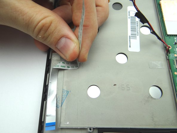
Finish removing the cable with your fingers.
-
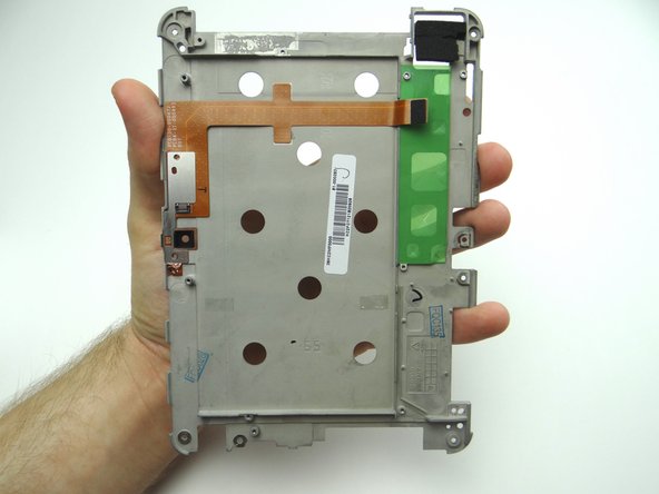
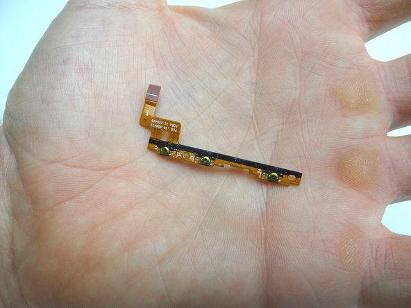
Place cable in COMPARTMENT E.
-
-
-
Seat the volume & power cable from COMPARTMENT E. Adhere it to the inside wall of the display.
-
-
-
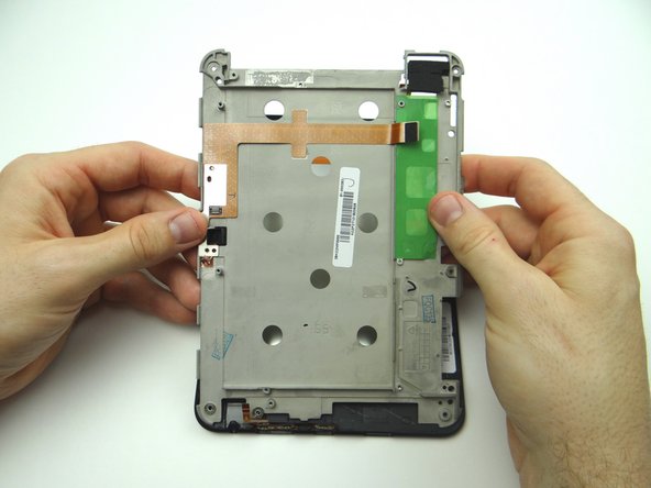
Seat mid-plate on display assembly:
-
Carefully guide the LCD and digitizer cables through their openings in the upper-right corner.
-
-
-
From COMPARTMENT D, replace camera:
-
Seat and connect it.
-
-
-
Picture 1: Seat the lower speaker from ZONE II.
-
Pictures 2 & 3: Run the speaker cable along the outside wall of the battery chamber on the mid-frame.
-
-
-
Picture 1: From ZONE V, guide the HDMI and charging port (red square) in first then continue to seat logic board.
-
Picture 2: Adhere the edge of the copper tape to the mid-plate.
-
Picture 3: Make sure the lower speaker cable is feed through the opening in the logic board as pictured.
-
-
-
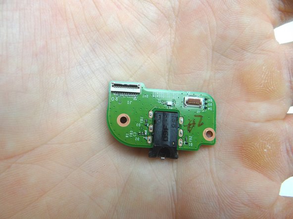
From COMPARTMENT D, replace headphone jack board.
-
Replace two 3.1 mm #00 Phillips screws from SLOT 4.
-
-
-
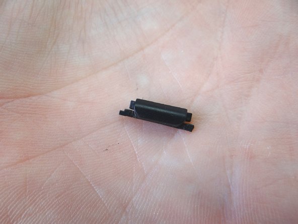
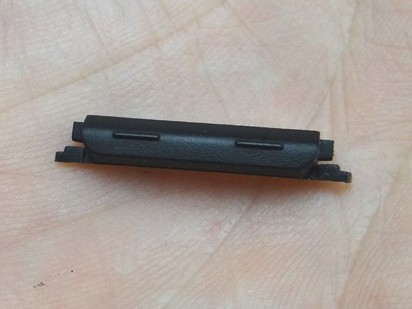
Maintain orientation from Picture 1:
-
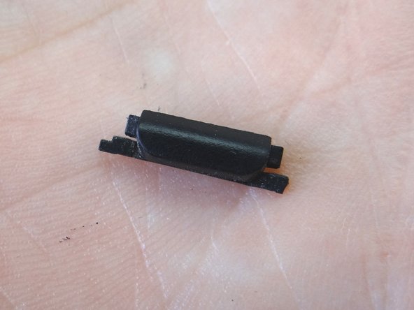
From COMPARTMENT B, replace power button.
-
-
-
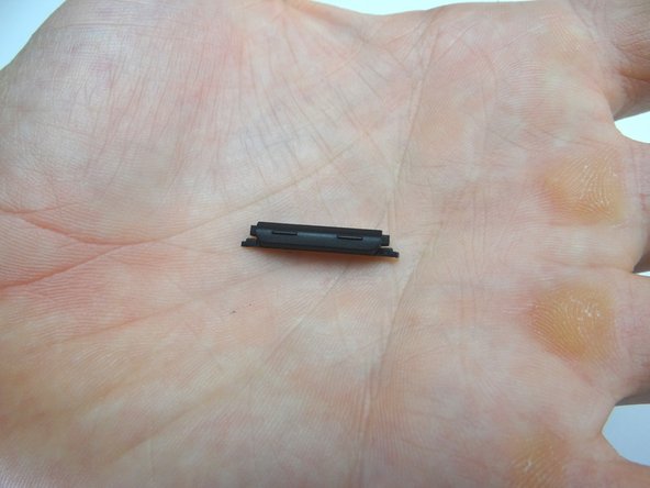
Maintain orientation from Picture 1:
-
From COMPARTMENT A, replace volume rocker.
-
-
-
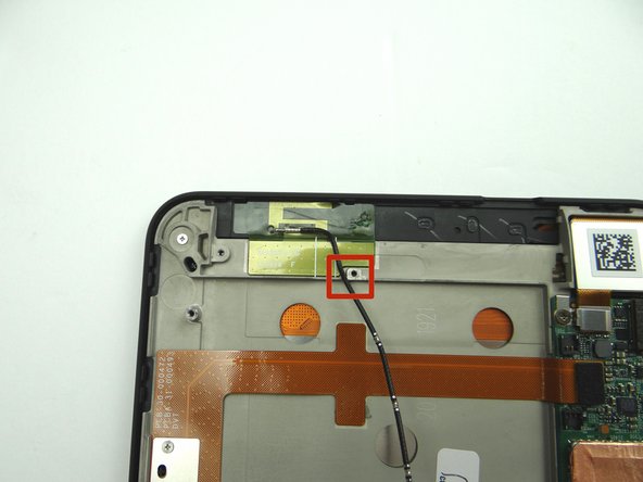
From COMPARTMENT C, replace antenna.
-
Lay the cable next to the screw socket as pictured.
-
-
-
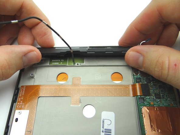
Seat top speaker from ZONE I.
-
Stand the antenna cable up as shown in Picture 3 so it's out of the way when you seat the battery.
-
-
-
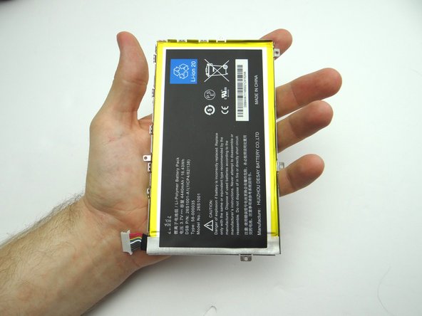
Replace battery from ZONE V. Make sure the antenna cable & lower speaker cable don't get trapped underneath.
-
-
-
Picture 1: Push both sides of battery connector evenly into the socket.
-
Picture 2: The connector should look like this (cannot see gold contacts) if seated properly.
-