
Parts
No parts specified.
-
-
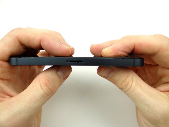
Picture 1: Push down on SIM card ejector opening with a large paper clip to pop up the tray.
-
Picture 2: Remove SIM card tray and SIM card. Place both in Sandbox COMPARTMENT A.
-
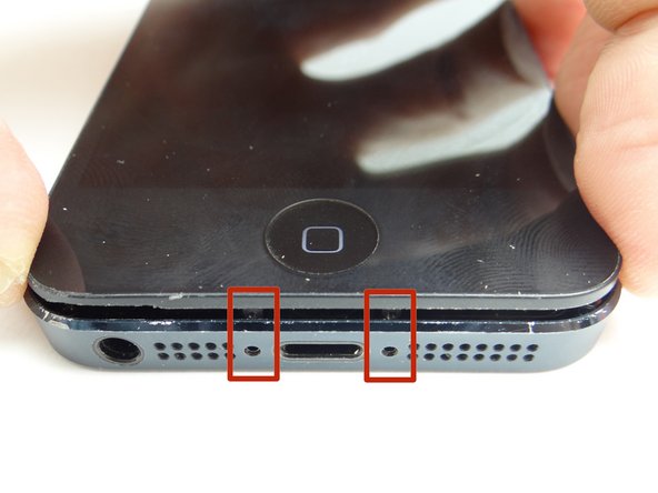
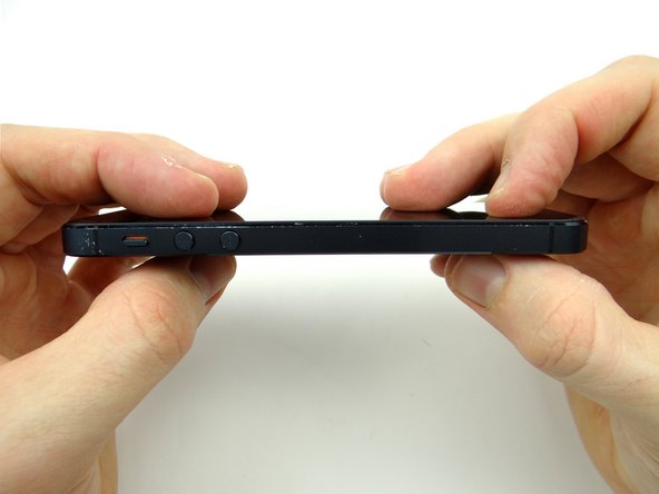
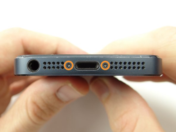
Picture 3: Remove two 3.6 mm Pentalobe screws near charging port. Place screws in Sandbox SLOT 1.
-
-
-
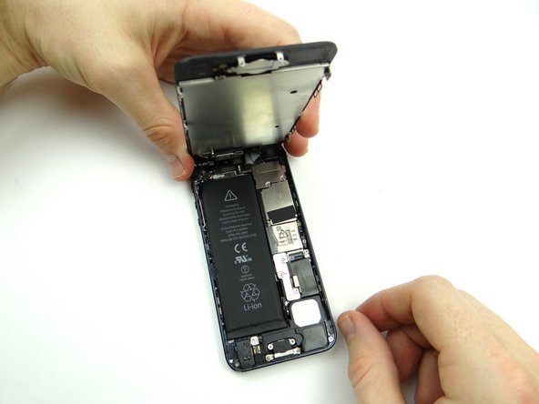
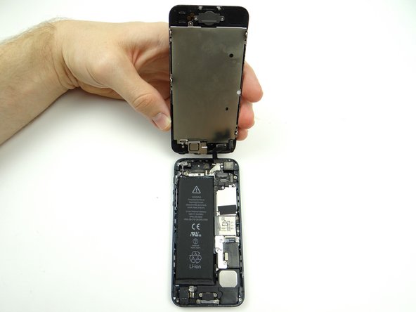
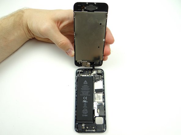
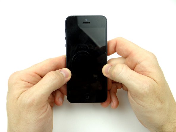
Picture 1: The iPhone 5 opens like a book with the top edge acting as a hinge.
-
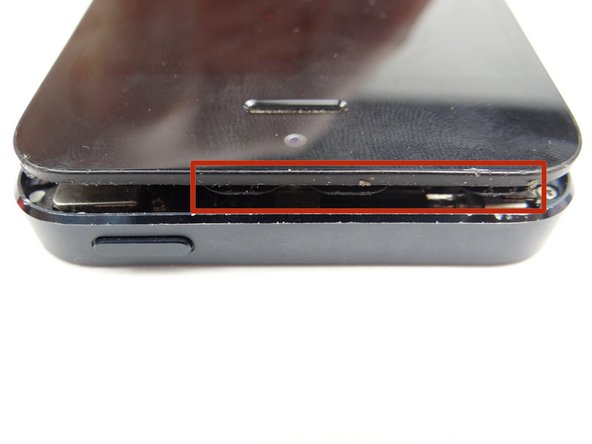
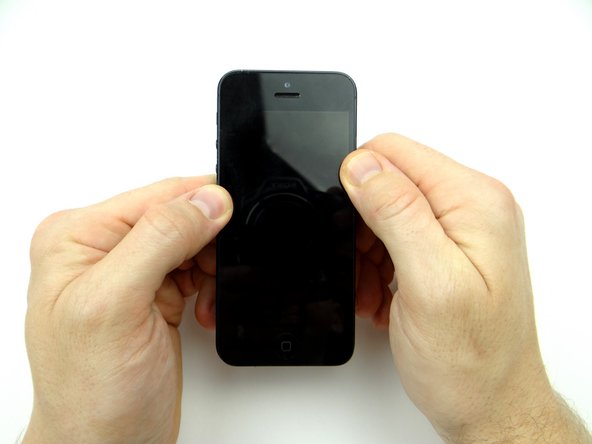
Picture 2: The front panel is held shut tightly with clips on both sides of the display.
-
Picture 3: There are three cables attached in the upper-right corner of the interior. Be careful not to put tension on these cables as you open the iPhone.
-
We show you how to release the clips and safely open the phone over the next few steps.
-
-
-
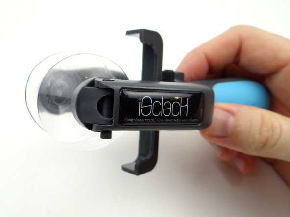
The iSclack tool (double suction cups) is best if you intend to reuse the screen. It also works on most cracked screens if you cover the screen with tape as shown in Step 1.
-
The iSesamo is used when it's impossible to create suction.
-
We demonstrate the iSesamo method over the next three steps. Skip to step 9 if you're able to use the iSlack tool.
-
-
-
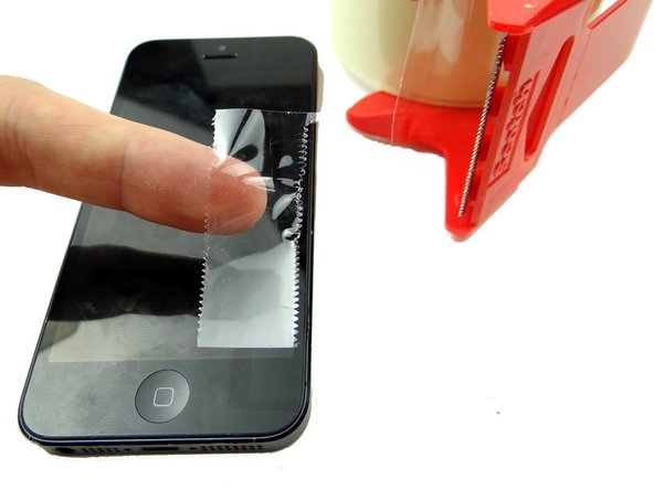
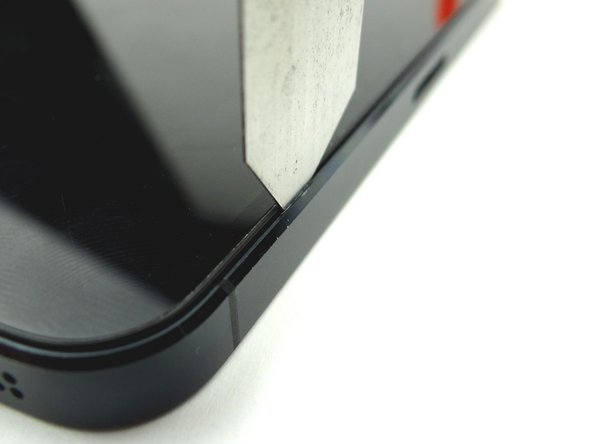
Cut a thin strip of packing tape and fold it over the lower-right corner of the iPhone.
-
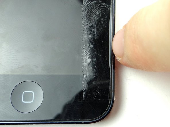
Run your fingernail in the groove between the front panel and rear case.
-
The tape protects the rear case from being scratched by the iSesamo tool in the next step. However, we removed the tape to improve picture clarity.
-
-
-
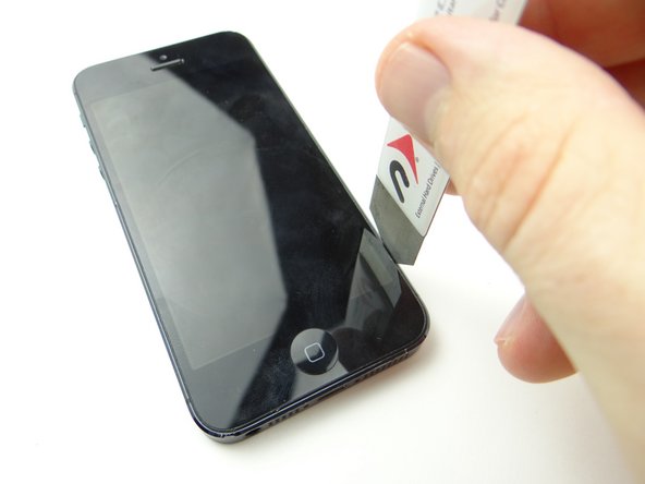
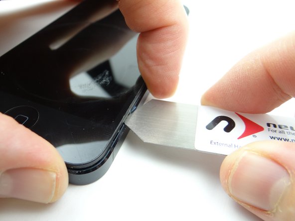
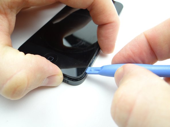
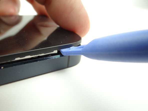
Picture 1: Insert the blue pry tool in the lower-right corner, then twist to pry the front panel up from the rear case.
-
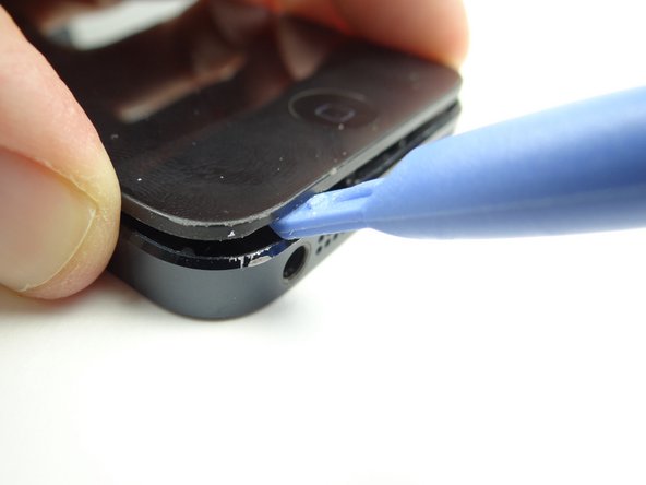
Picture 2: Repeat in the lower-left corner.
-
Picture 3: Work your way up both sides of the iPhone, twisting to open the device from the bottom (as shown in the previous step)
-
Remove the thin strip of tape packing tape.
-
-
-
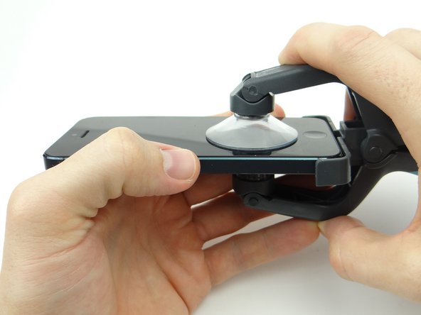
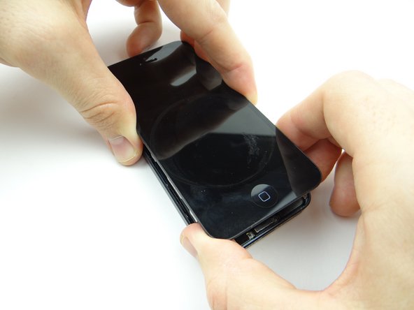
Picture 1: Close the iSclack suction cups on either side of the iPhone.
-
Note the placement of the top suction cup centered above the home button.
-
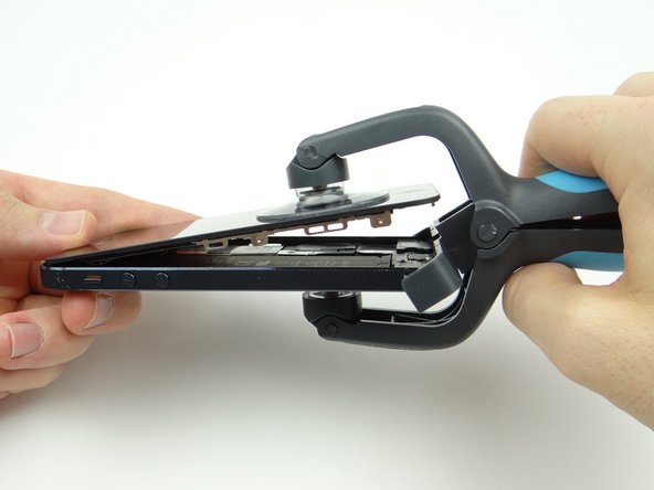
Picture 2: The iSclack tool opens the phone in one rapid motion: use your left hand to moderately squeeze the top of the iPhone while you open it with your right hand.
-
-
-
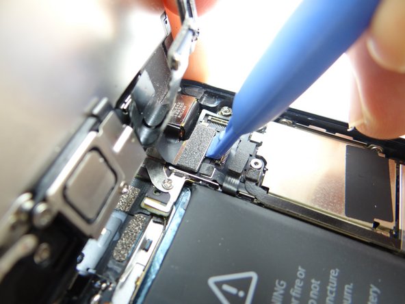
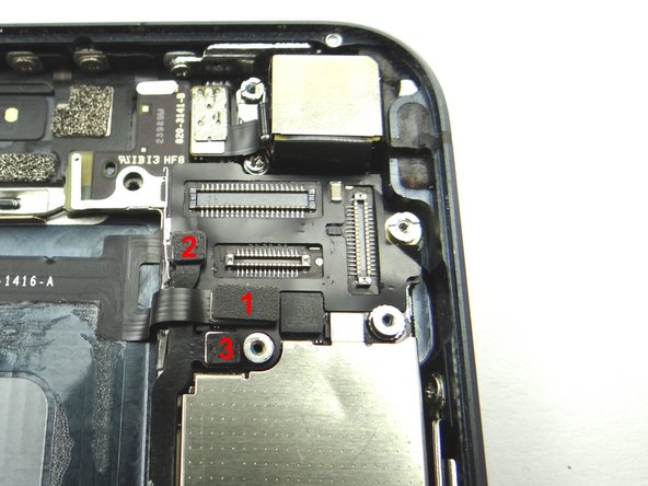
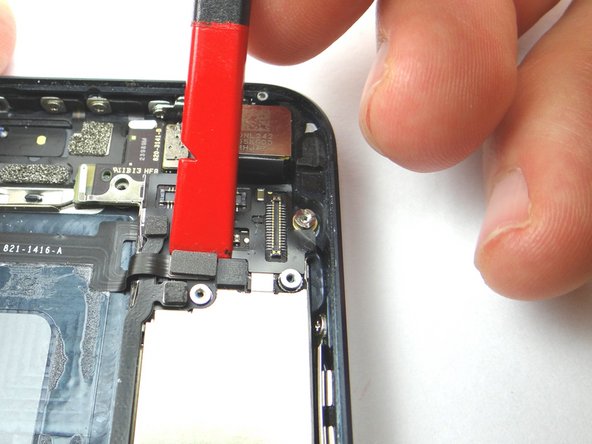
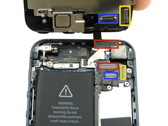
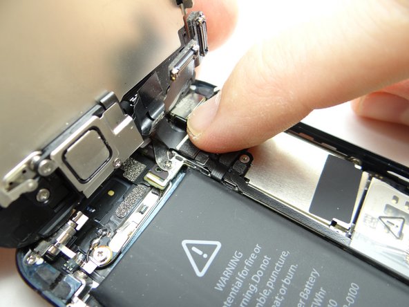
Picture 1: Release front-facing camera and sensor cable.
-
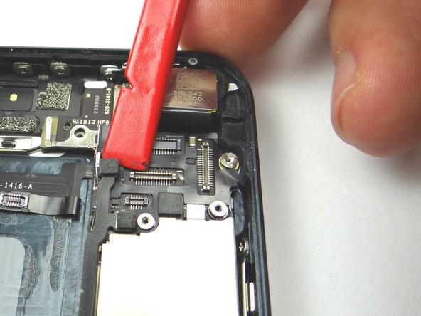
Picture 2: Release digitizer cable.
-
Picture 3: Release LCD cable.
-
-
-
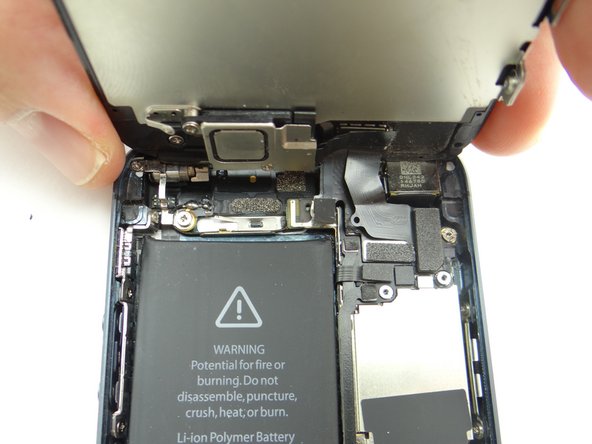
Picture 1: Separate front panel from rear case.
-
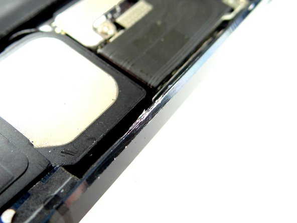
Picture 2: Check if the iSesamo scratched the rear case bezel.
-
Picture 3: If you're repairing a black iPhone, use a black sharpie to color any scratches caused by the iSesamo tool. Be careful to only color over the scratched area.
-
Don't color over scratches on a white iPhone!
-
Place the rear case Sandbox ZONE I.
-
-
-
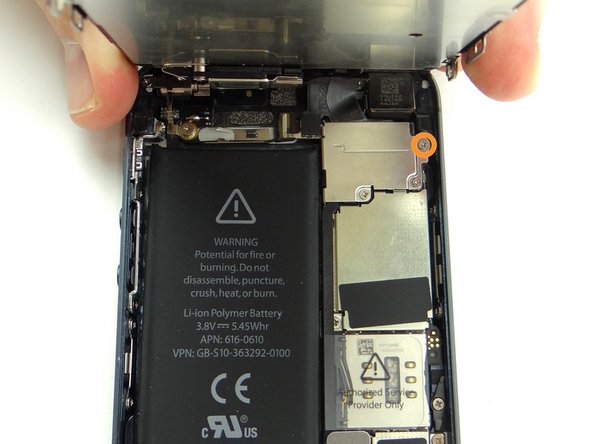
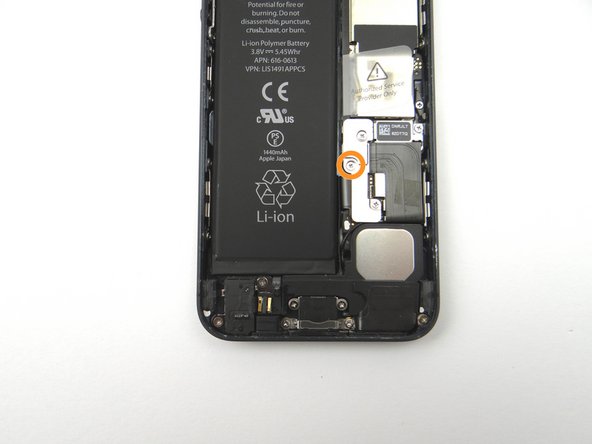
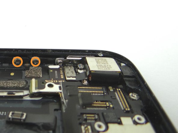
Picture 1: Remove 1.8 mm Phillips screw and place in SLOT 4.
-
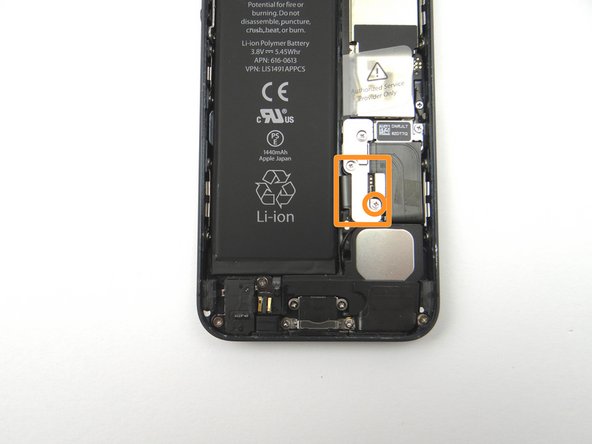
Picture 2: Remove 1.6 mm Phillips screw and place in SLOT 5. Remove the shield held in place by the screws and place in SLOT 5 with the 1.6 mm Phillips screw.
-
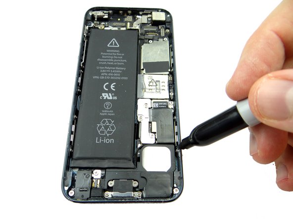
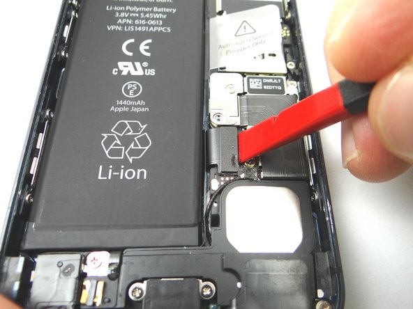
Picture 3: Use Black Spudger to gently pry up the battery connector.
-
-
-
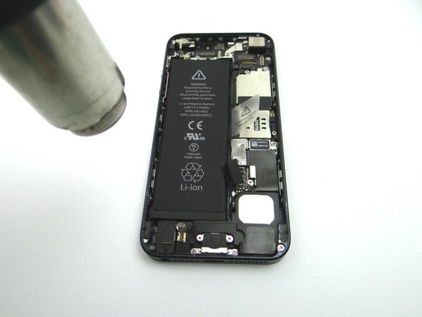
Apply low-level heat (100* Celcius or less) to edges of battery for 60 seconds to loosen the adhesive securing the battery to the iPhone.
-
Work your way along the right and top of the battery, gently prying up with the Black Spudger to free the battery from the adhesive securing it to the rear case.
-
Remove the battery and place it in ZONE II.
-
-
-
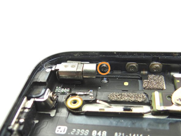
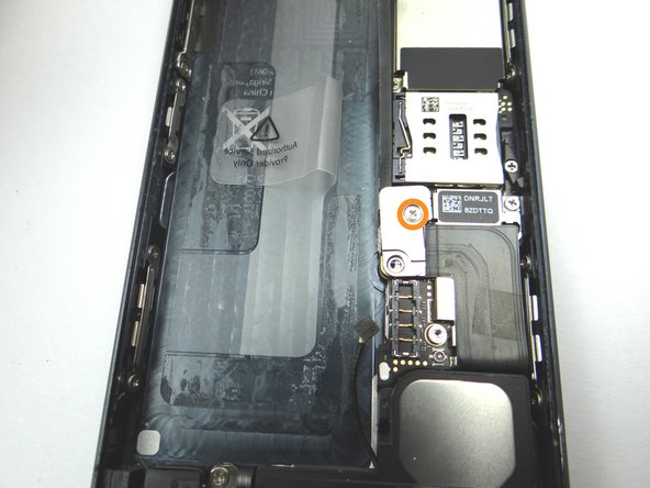
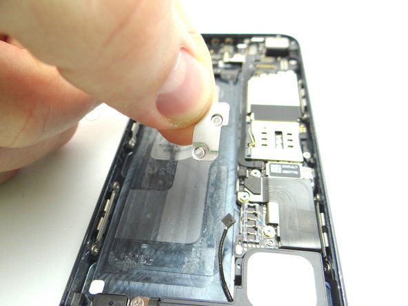
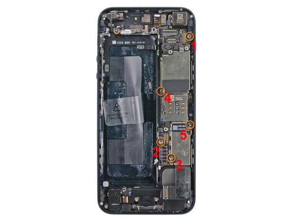
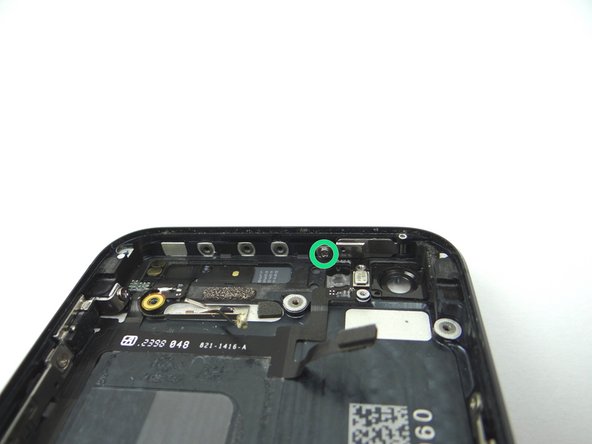
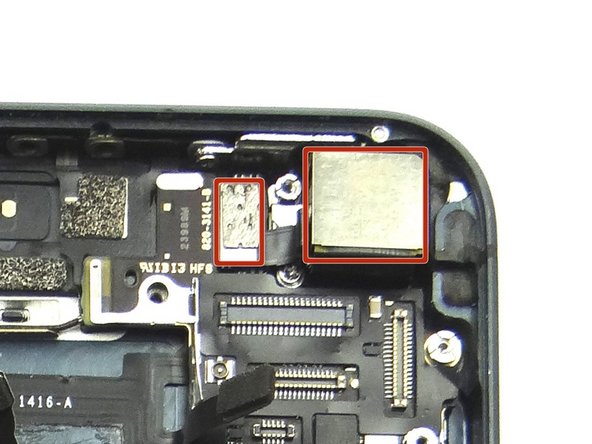
Picture 1: Remove 2.3 mm Phillips screw and place into SLOT 6.
-
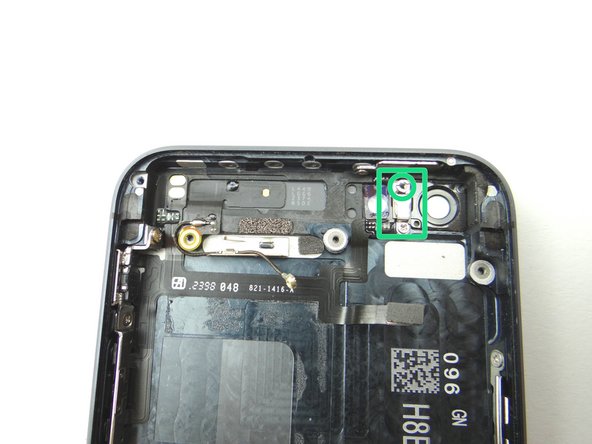
Picture 2: Remove 1.7 mm Phillips screw and place into SLOT 7.
-
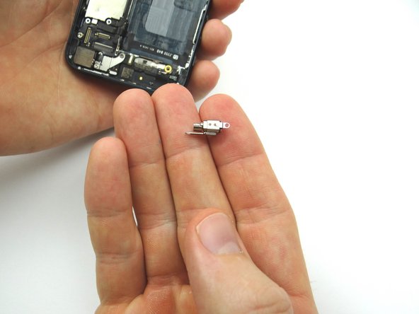
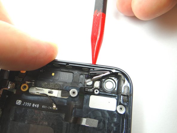
Picture 3: Remove vibrator bracket and place into SLOT 7 with the 1.7 mm Phillips screw.
-
-
-
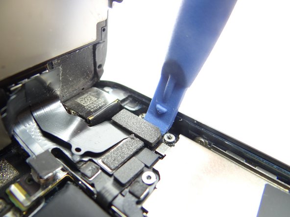
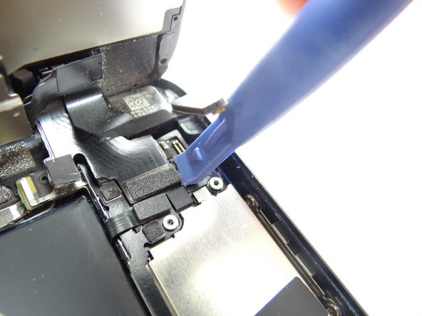
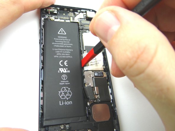
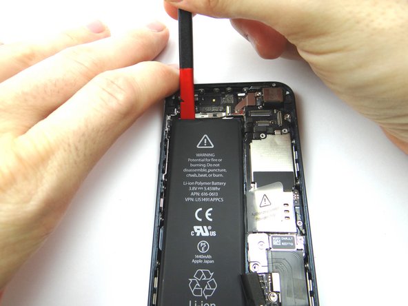
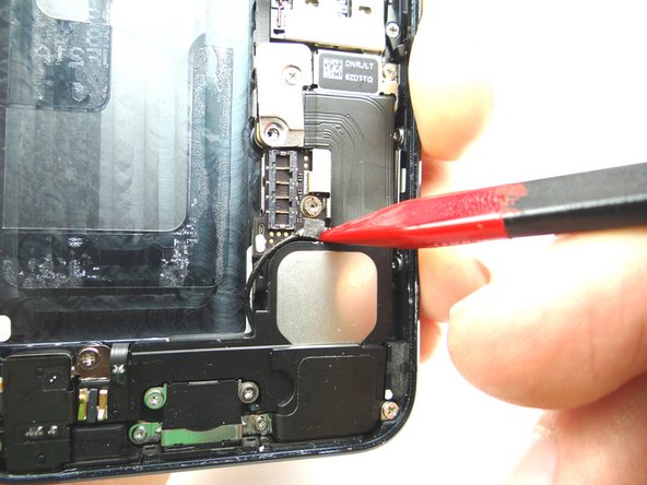
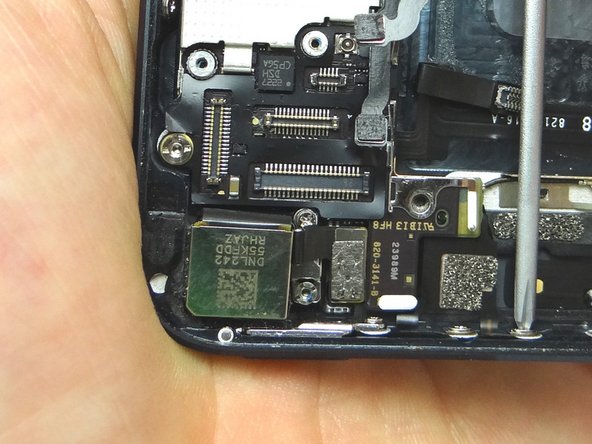
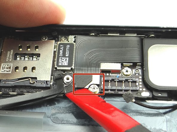
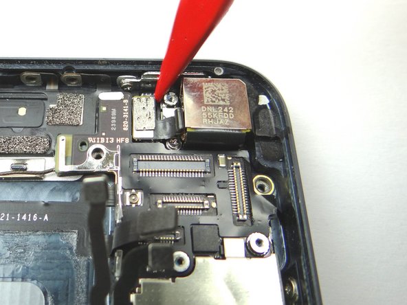
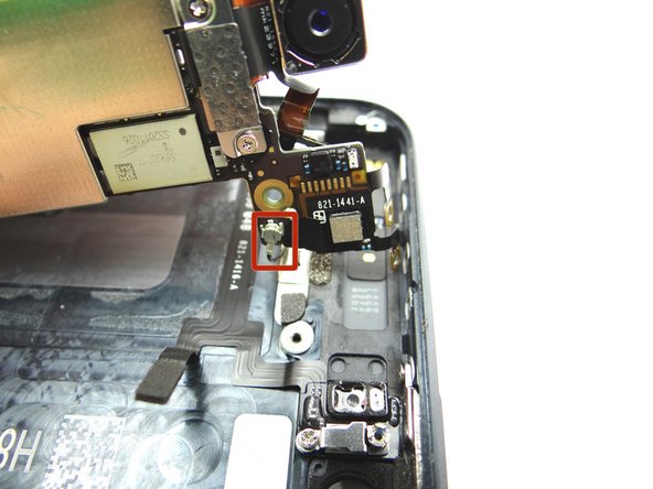
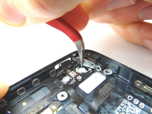
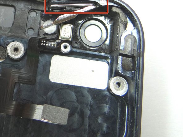
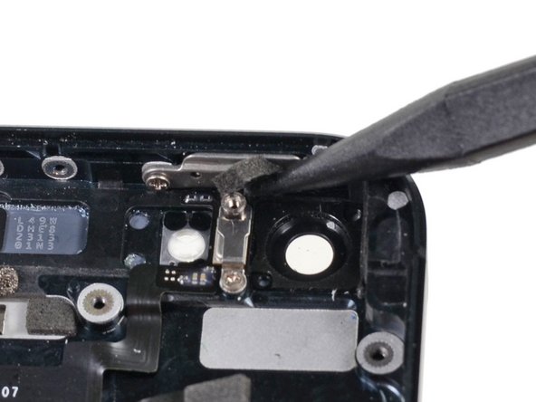
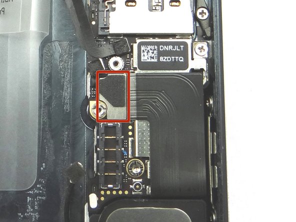
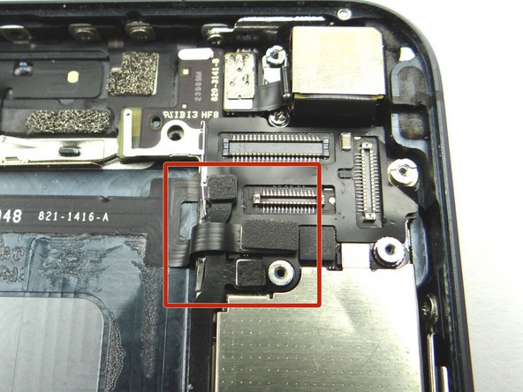
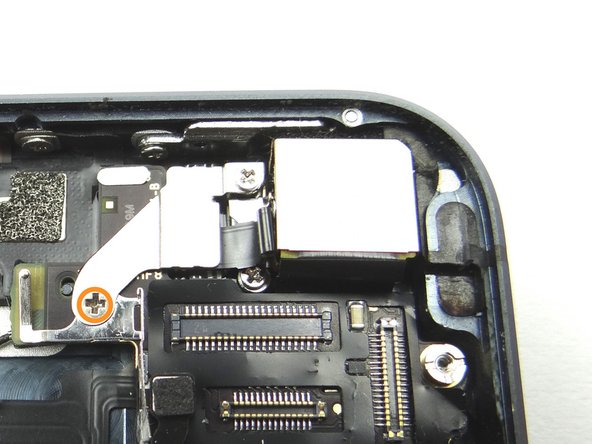
Picture 1: Use the pointed tip of the Black Spudger to pry the cellular antenna connector from its socket.
-
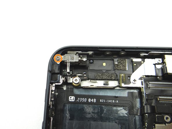
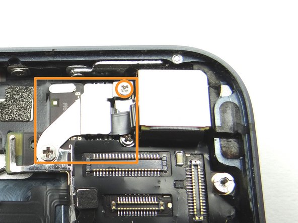
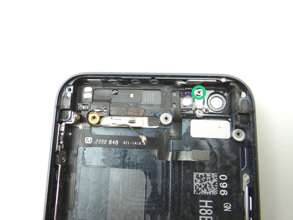
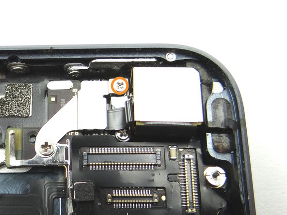
Picture 2: Remove one 2.3 mm Phillips screw and place in SLOT 9.
-
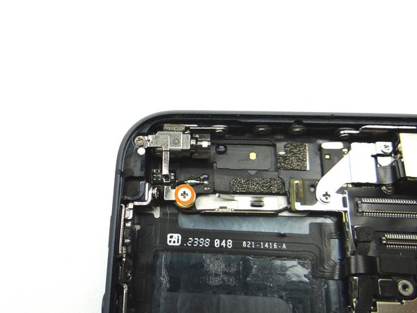
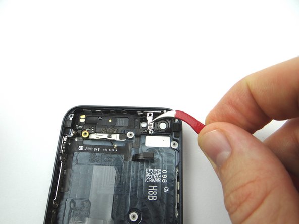
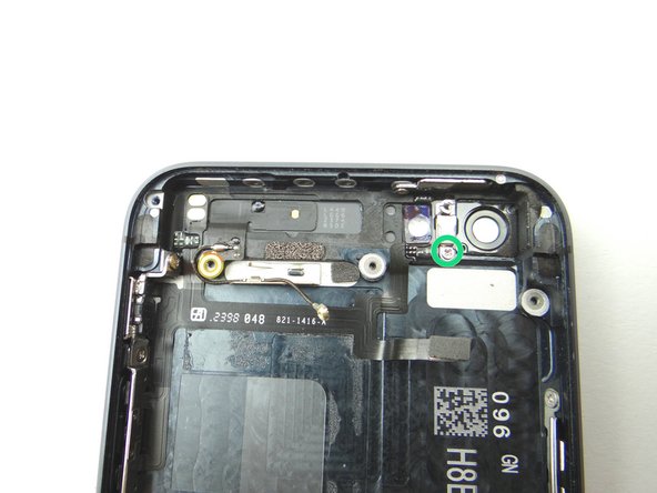
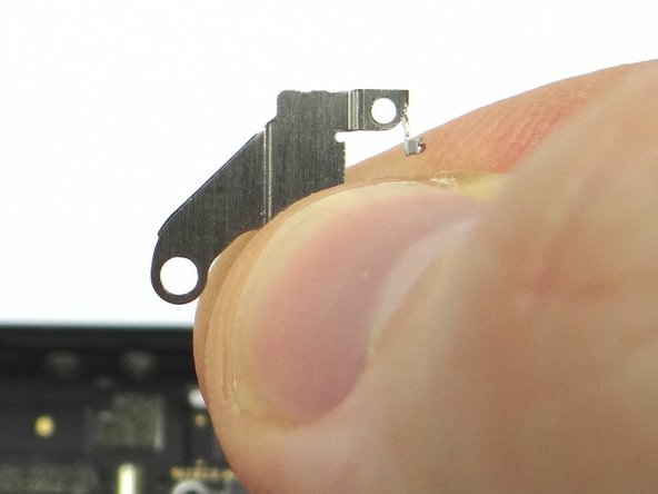
Picture 3: Remove one 1.5 mm Phillips screw and place in SLOT 10. Next, remove the shield and place in SLOT 10 with the Phillips screw.
-
-
-
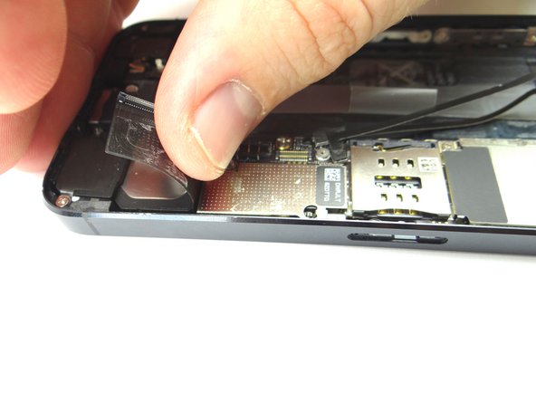
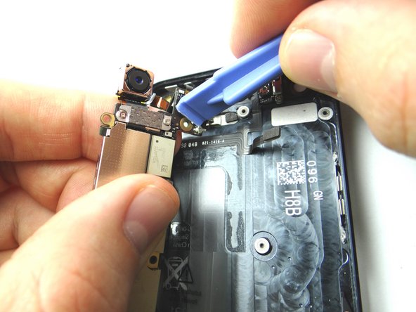
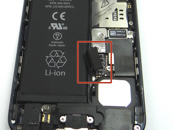
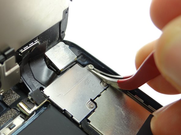
Picture 1: Place flat end of spudger under left side of charging port assembly cable. Gently twist your hand clockwise releasing the cable from its socket on the logic board.
-
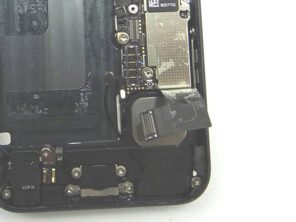
Picture 2 & 3: The charging port assembly cable is adhered to the logic board – gently peel it free from the logic board, working top to bottom until cable is free of logic board. Be cautious as this cable is very fragile.
-
-
-
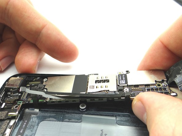
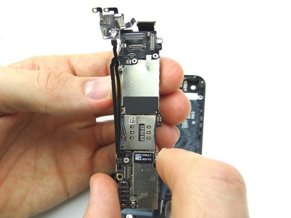
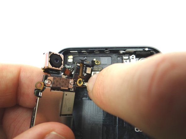
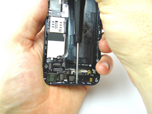
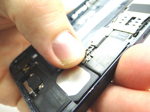
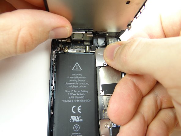
Picture 1: Carefully lift the logic board just high enough to pinch it with your left thumb and index finger.
-
Picture 2: Turn the logic board counter clockwise to reveal the wifi antenna connector.
-
Use caution when turning the logic board to ensure you do not rip the wifi antenna cable.
-
-
-
Use Black Spudger to remove foam rubber bumper covering the power button door. Place into COMPARTMENT C.
-
THE RUBBER BUMPER MAY OR MAY NOT BE PRESENT!
-
-
-
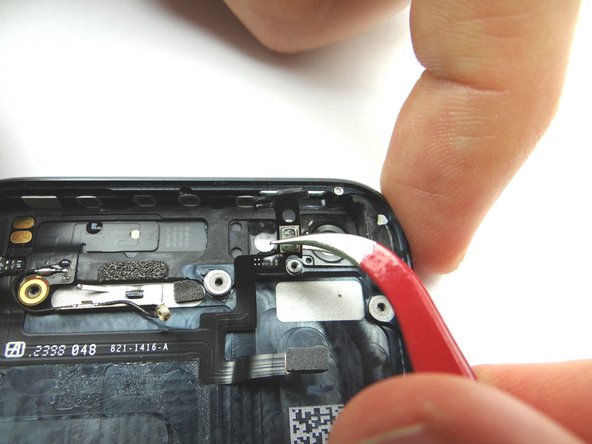
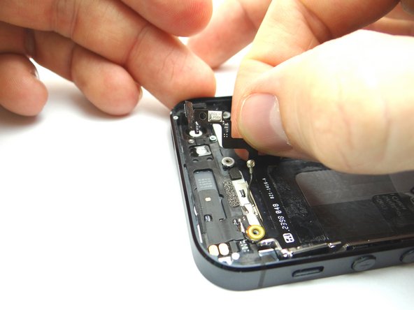
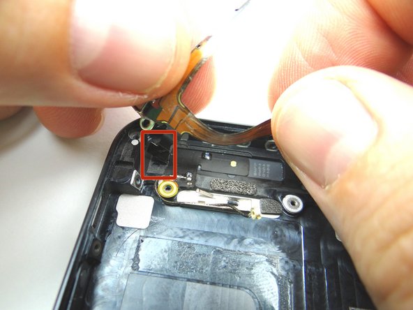
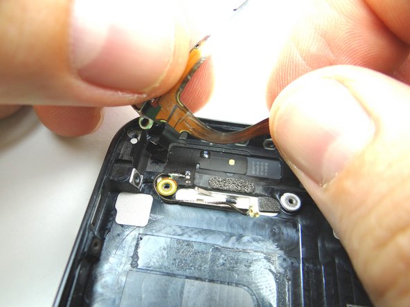
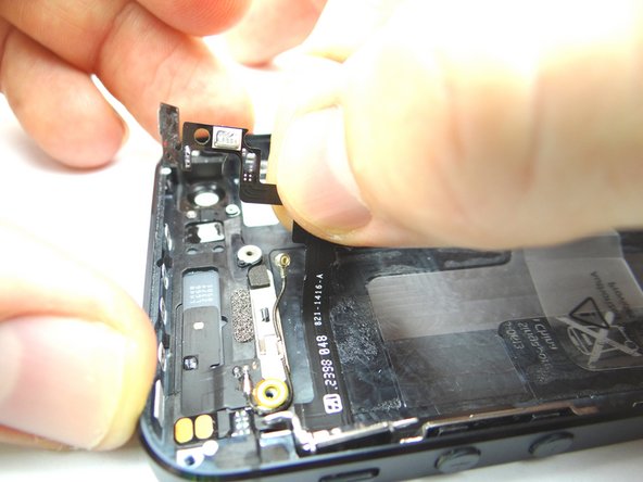
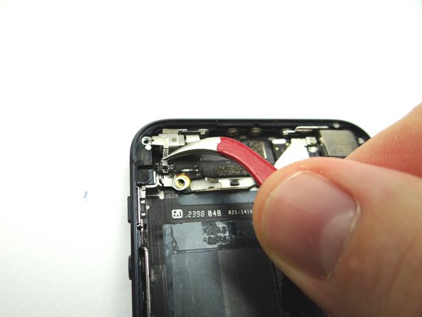
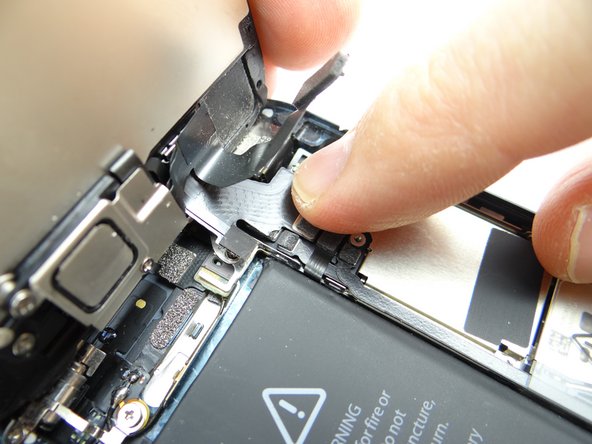
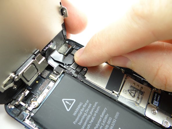
Picture 1: Use the tip of the Black Spudger to push through the power button and ribbon cable. Place power button in COMPARTMENT F.
-
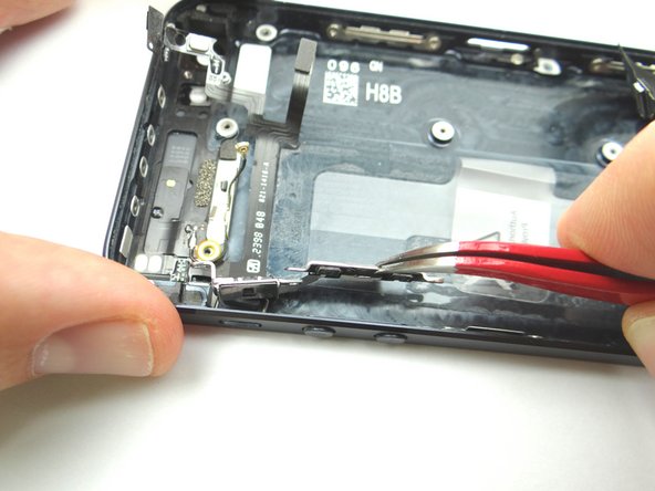
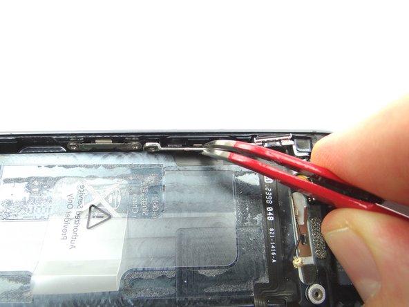
Picture 2: Use Curved Tip Tweezers to swing the metal power button door all the way open. The door will be stuck at a certain point, however it can swing past that point.
-
Picture 3: Use Curved Tip Tweezers to move the power button ribbon cable away from the top.
-
-
-
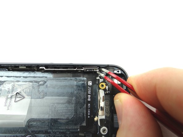
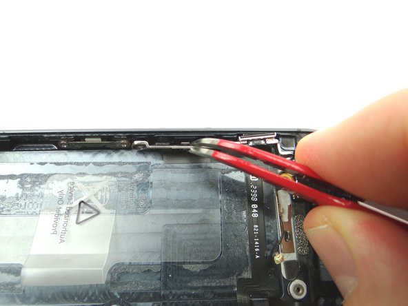
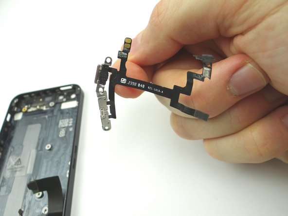
Picture 1: Replace the power button assembly / volume button assembly from ZONE III.
-
Picture 2: Place the contacts on the ribbon cable back into position in the top left portion of the rear case.
-
-
-
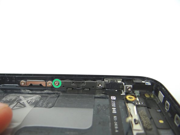
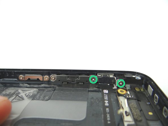
Picture 1: Replace the power button from COMPARTMENT F. Make sure the hinge is at the top of the button and closed. Align power button contact.
-
Picture 2: Shut the power button door. It will be stiff in a couple areas.
-
Picture 3: Replace one 1.9 mm Phillips screw from COMPARTMENT C.
-
Make sure the power button contact is lined up before re-assembling the phone. The button should depress exactly the same as a new iPhone.
-
-
-
Picture 1: Replace logic board from ZONE III.
-
Picture 2: Reconnect wifi antenna to the logic board.
-
Picture 3: Push the logic board down into its position on the mid-frame.
-
Make sure no cables get trapped under the logic board while re-installing it.
-
-
-
Picture 1: Replace the vibrator from COMPARTMENT B.
-
Picture 2: Replace the 1.6 mm Phillips screw from SLOT 8.
-
-
-
Picture 1: Replace the battery from ZONE II and reseat the battery connector to its socket on the logic board.
-
Picture 2: From SLOT 5, reseat the shield that goes over the top of the battery connector. Replace the 1.6 mm Phillips screw, also in SLOT 5, that goes into the bottom of the shield.
-
Picture 3: Secure the top of the shield with the 1.8 mm Phillips screw from SLOT 4.
-
-
-
Pictures 1 & 2: Line up the replacement front panel with the rear case. In the next step, you'll connect three front panel cables to the logic board.
-
Picture 3: This is what the cables will look like when you're finished.
-
-
-
Pictures 1 & 2: Angle the clips on the front panel into their sockets on the rear case.
-
Check the LCD and Digitizer before continuing:
-
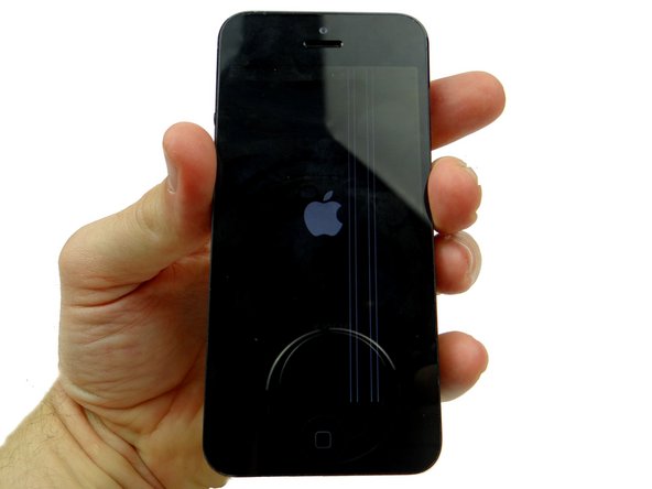
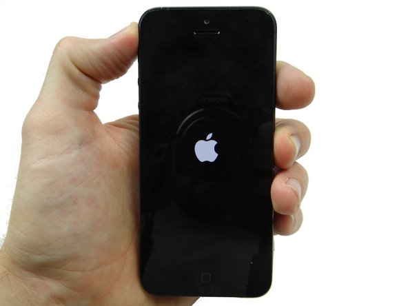
Picture 3: Power up the phone and don't close the front panel. If the LCD or digitizer aren't working perfectly (white lines are the most common issue), jump back to Step 11.
-
If the issue remains after reseating the cables, you'll likely need another display.
-
-
-
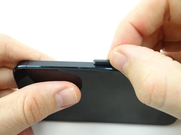
Picture 1: With the phone on the worktable, push the Pentalobe screw tabs in first.
-
This should take minimal pressure. Check for errant screws or other obstructions if the device is difficult to close.
-
Pictures 2 & 3: Then, push in with your thumbs just below the middle of the display and work your way up.
-


Cancel: I did not complete this guide.
One other person completed this guide.