-
-
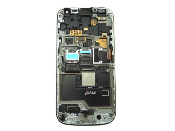
Power down the device.
-
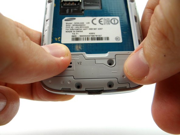
Remove battery cover and battery. Place in ZONE I.
-
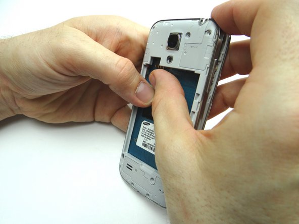
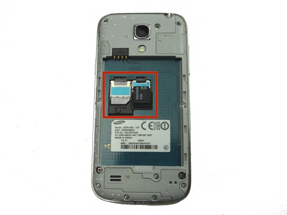
Remove SIM card and SD card. Place in COMPARTMENT A.
-
-
-
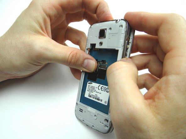
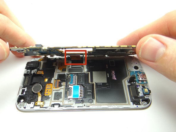
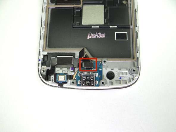
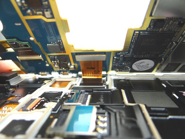
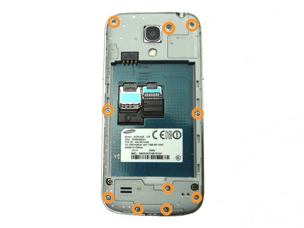
Remove metal shield:
-
Use curved-tip tweezers to grab metal shield and work it around the tabs creating tension (marked in Picture 2).
-
-
-
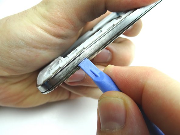
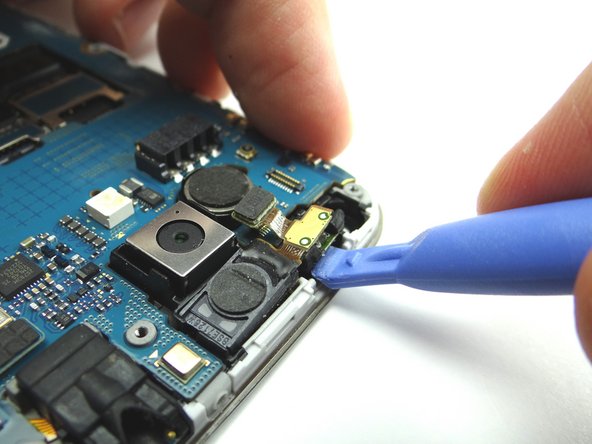
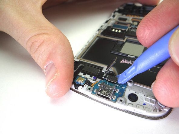
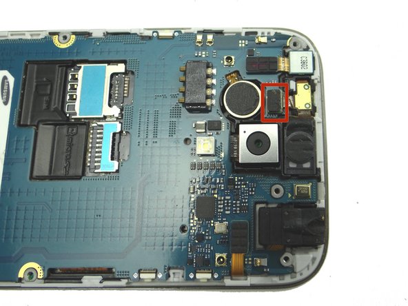
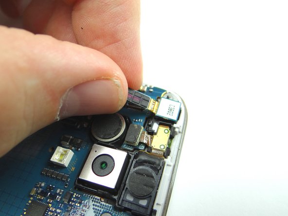
Picture 1: Use blue pry tool to disconnect earpiece speaker / proximity sensor cable.
-
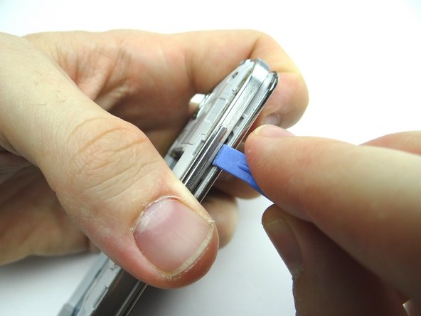
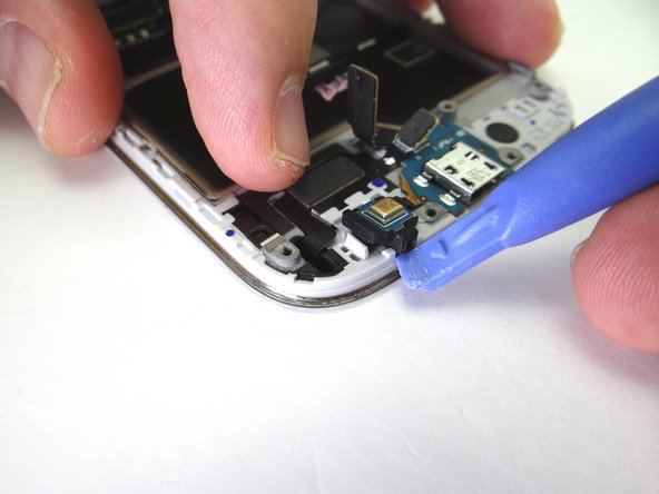
Picture 2: Use blue pry tool to lift proximity sensor up enough to grab with your fingers.
-
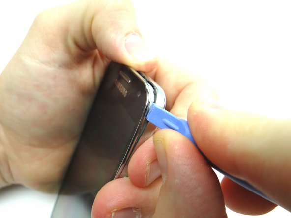
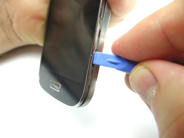
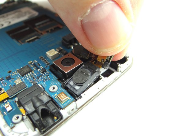
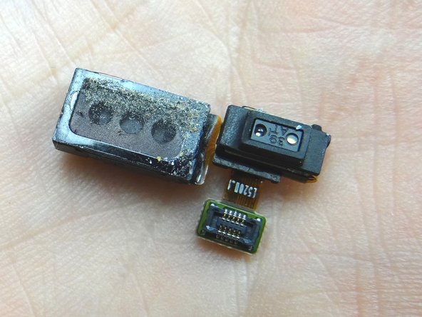
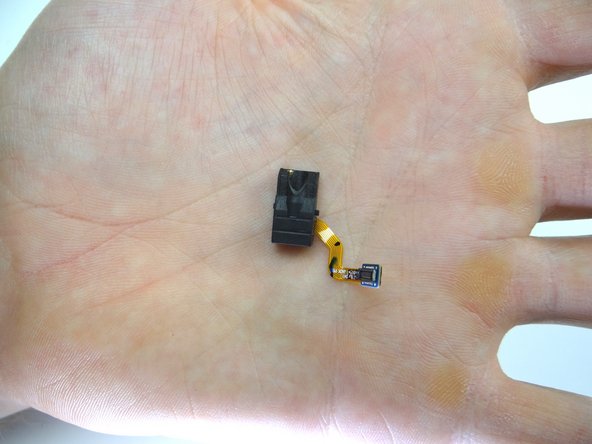
Picture 3: Peel up earpiece speaker / proximity sensor assembly.
-
-
-
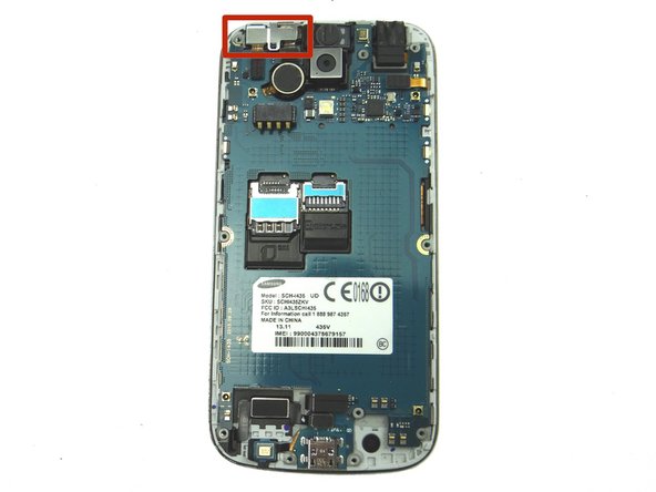
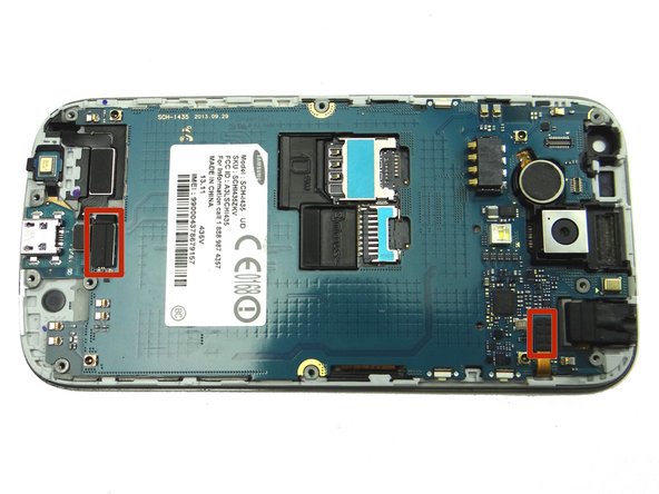
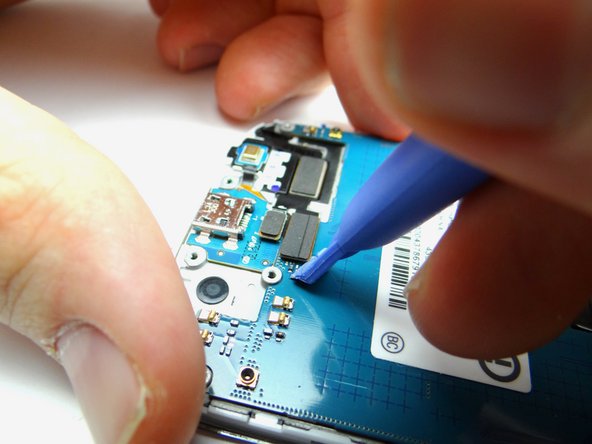
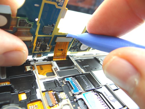
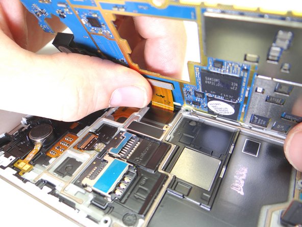
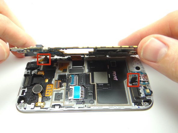
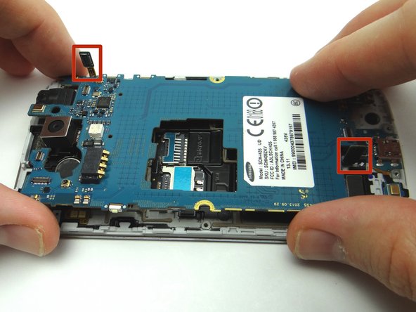
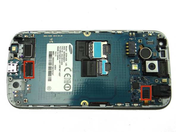
Picture 1: Disconnect the pictured cables:
-
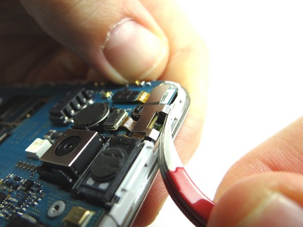
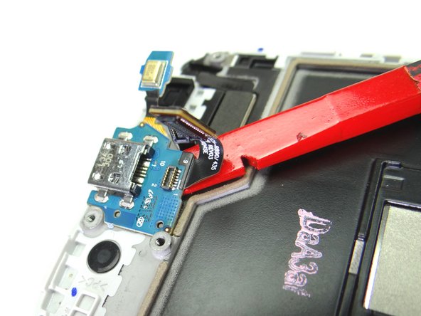
Picture 2: Use the blue pry tool to disconnect charging port cable.
-
Picture 3: Disconnect headphone jack cable.
-
-
-
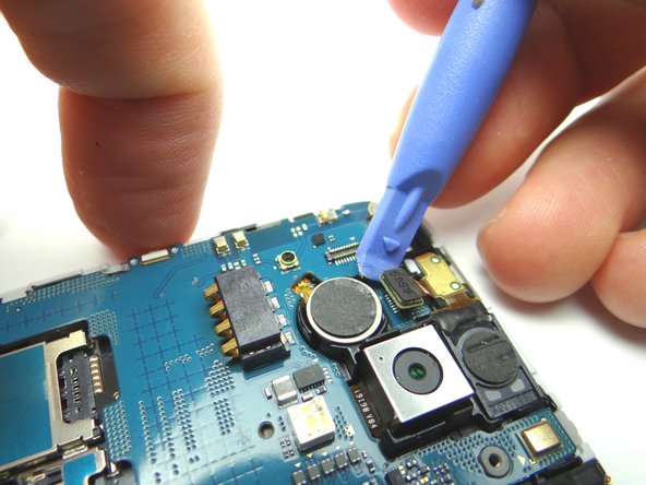
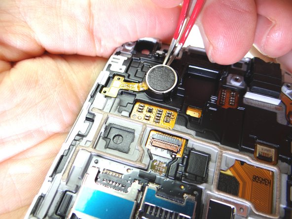
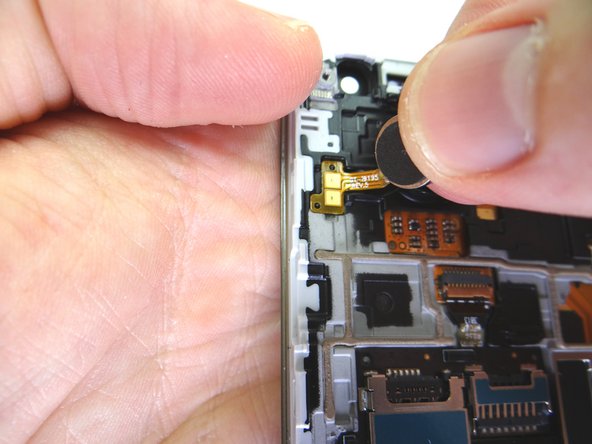
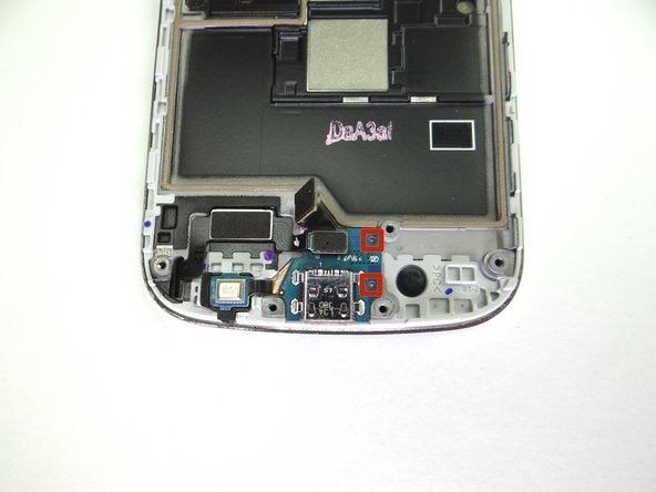
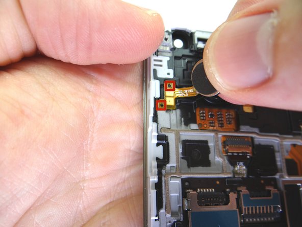
Picture 1: With the curved-tip tweezers in the closed position, wedge the tip under the vibrator and pry up enough to grab the vibrator with your fingers.
-
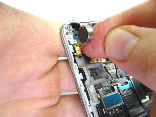
Picture 2: Carefully peel up the vibrator with your fingers.
-
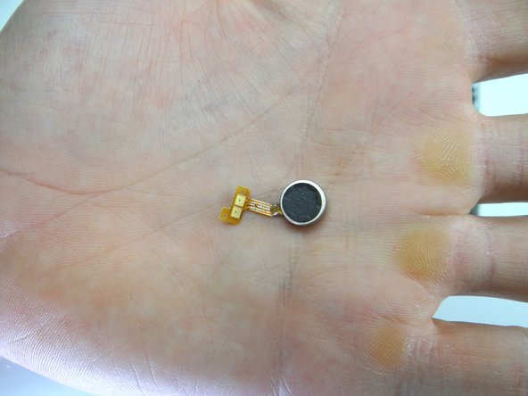
Picture 3: Place vibrator in COMPARTMENT D.
-
-
-
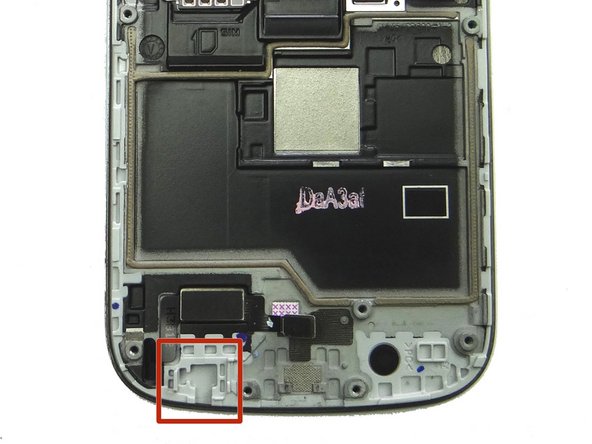
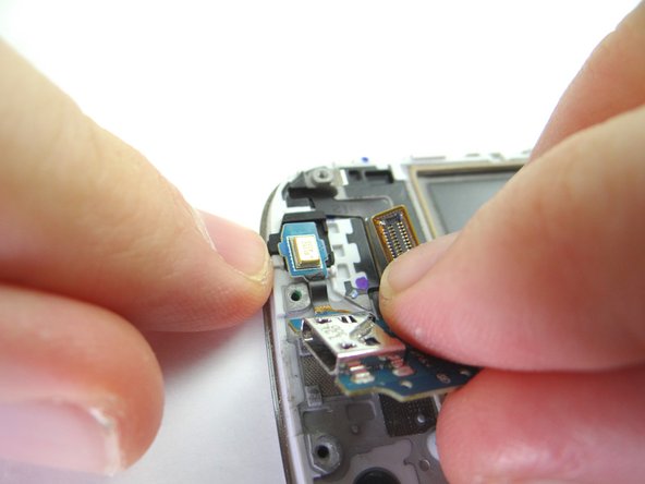
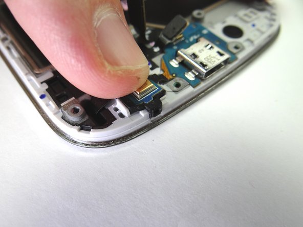
Insert the pointed end of the spudger in the headphone jack and wiggle just enough to loosen it.
-
Remove it with your fingers.
-
Place in COMPARTMENT D.
-
-
-
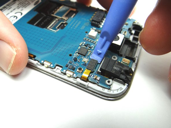
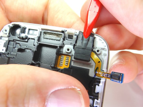
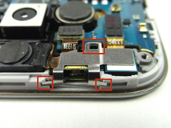
Pictures 1 & 2: Use blue pry tool to disconnect home button cable.
-
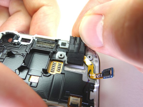
Picture 3: Dislodge the microphone from its socket.
-
Don't try to remove the microphone - it's part of the charging port assembly.
-
-
-
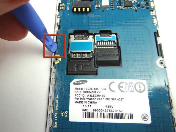
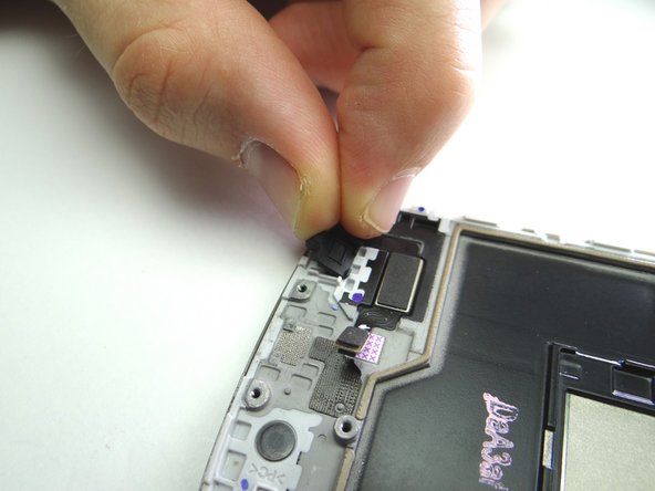
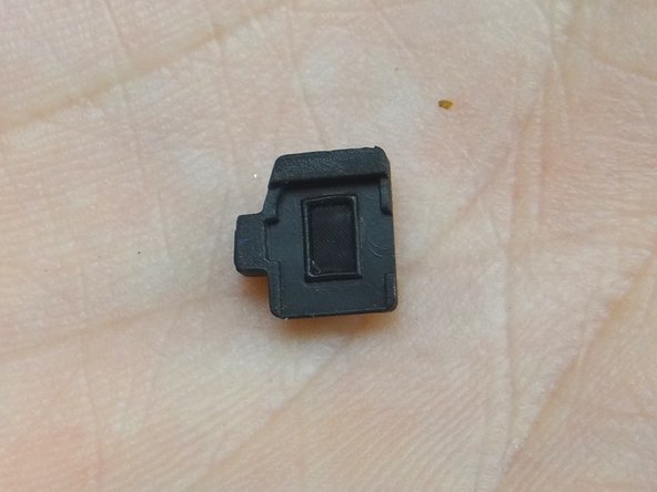
Peel up the rubber microphone gasket
-
Place gasket in COMPARTMENT F.
-
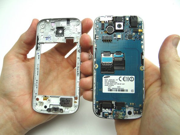
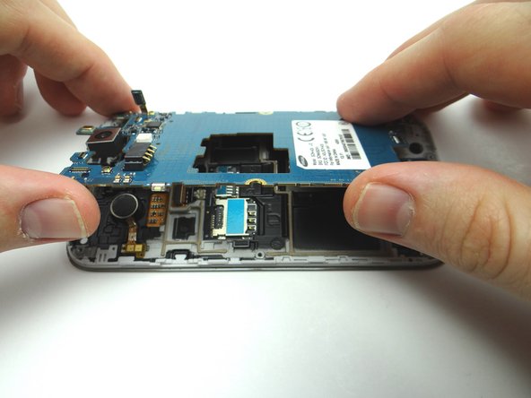
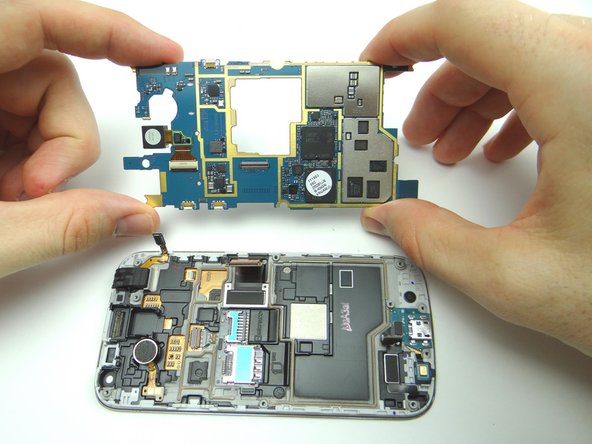
Display Assembly remains.
-
-
-
Retrieve replacement display.
-
Seat microphone gasket from COMPARTMENT F.
-
-
-
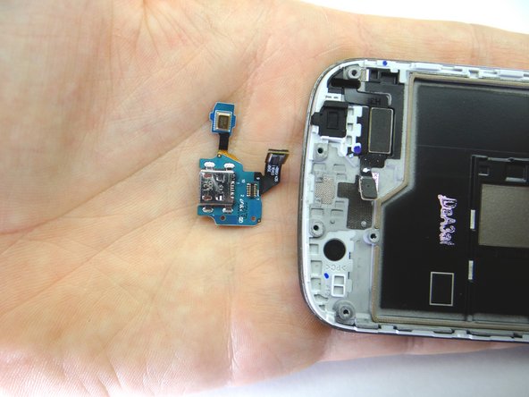
Seat charging port / microphone assembly from COMPARTMENT E:
-
Guide microphone in first then continue seating the charging port.
-
-
-
Seat vibrator from COMPARTMENT D:
-
Line up two tabs in red squares first, then continue seating vibrator with your fingers.
-
-
-
Bring logic board and front panel together at a 45° angle. Push display cable firmly into place.
-
-
-
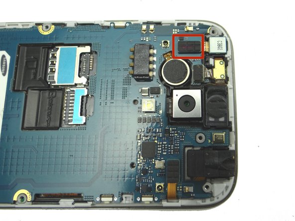
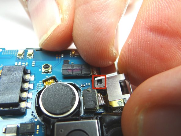
From COMPARTMENT C, use your fingers to seat earpiece speaker / proximity sensor.
-
Connect the cable.
-
-
-
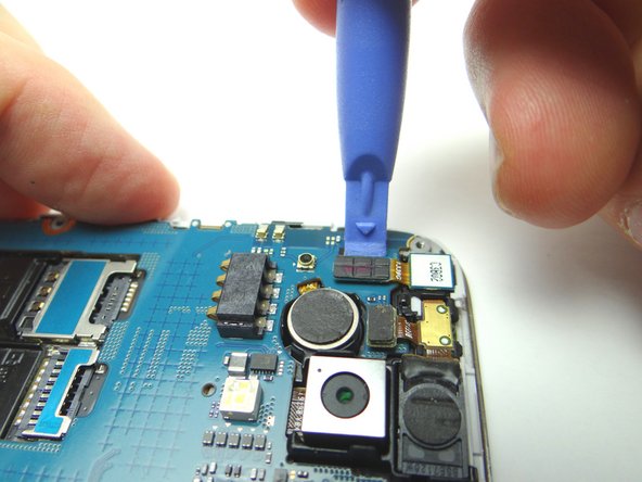
From COMPARTMENT C, seat front-facing camera with your fingers.
-
Connect the cable.
-
-
-
Picture 1: Line up mid-frame with front panel. Seat bottom near charging port first.
-
Picture 2: Work your way to the top.
-
Picture 3: Check the perimeter to make sure all edges are snapped into place.
-