-
-
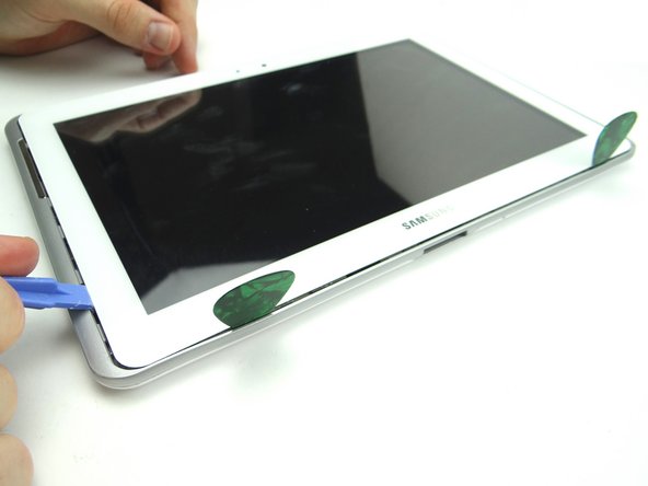
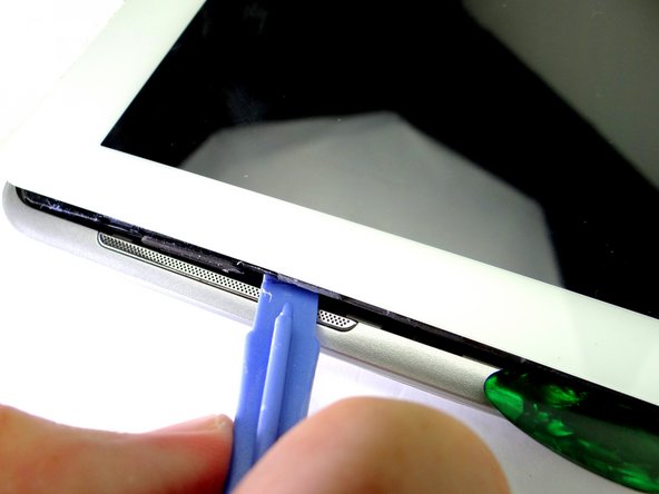
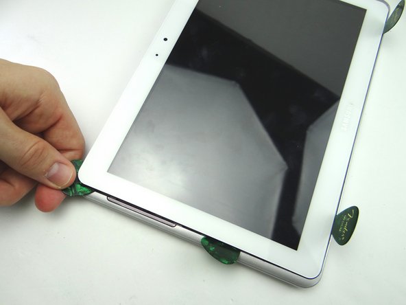
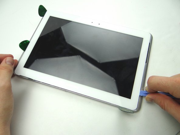
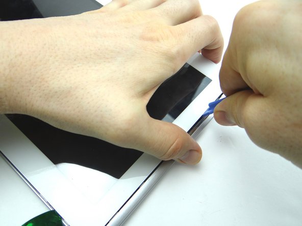
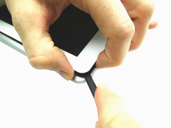
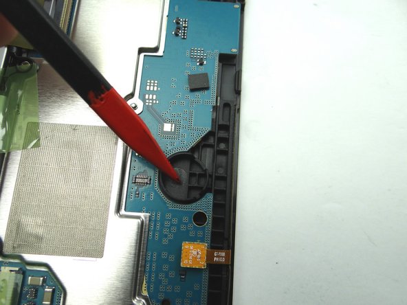
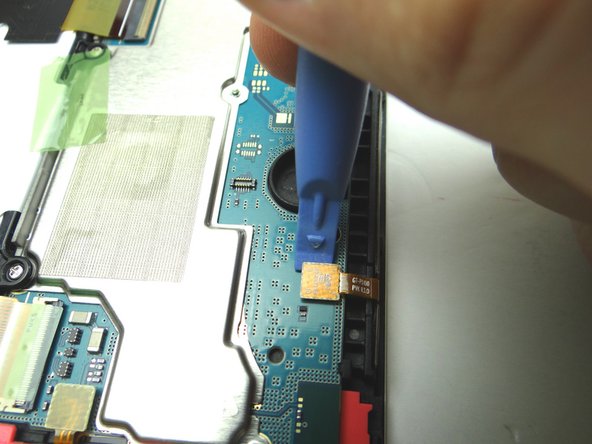
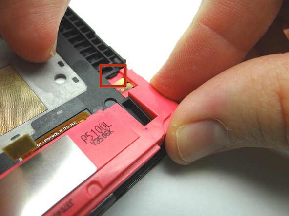
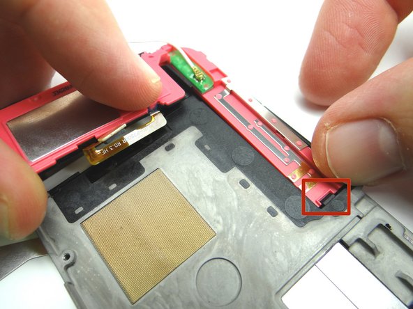
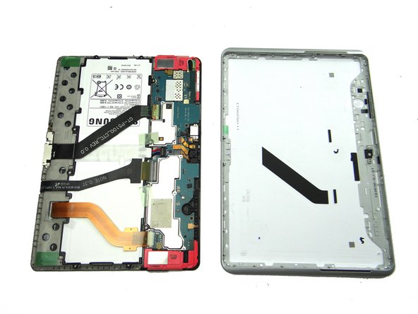
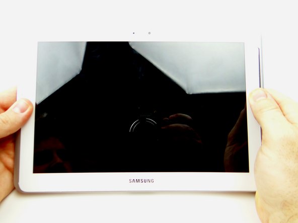
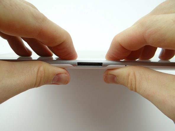
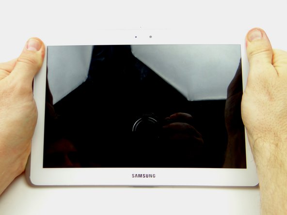
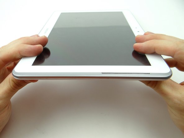
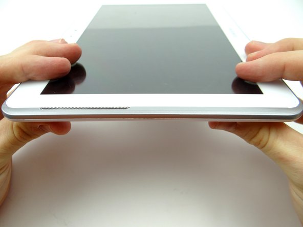
Pictures 1 & 2: Insert a wide blue pry tool between the rear case and front panel at the bottom of the tablet, an inch left of the Samsung logo. Sweep left, then insert a guitar pick to hold the left side open. Work your way right with the blue pry tool.
-
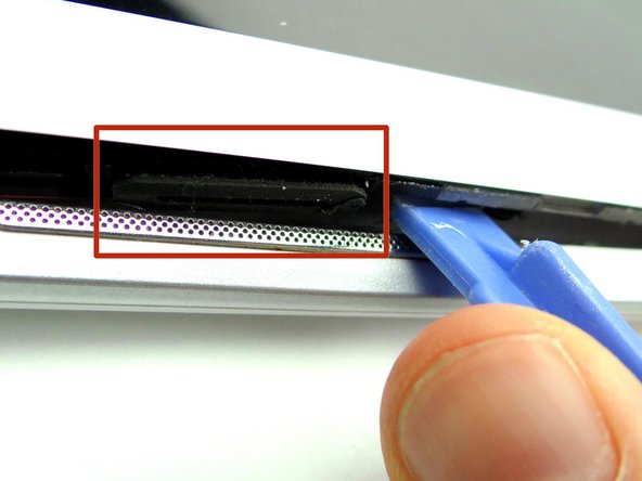
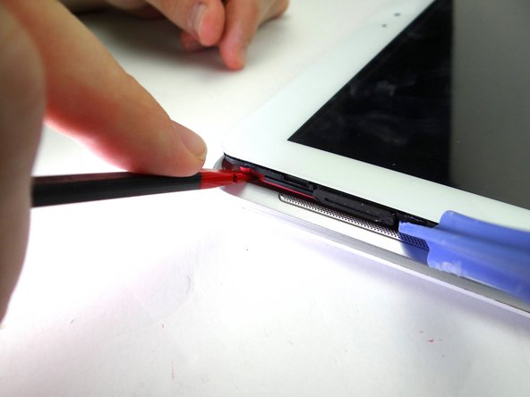
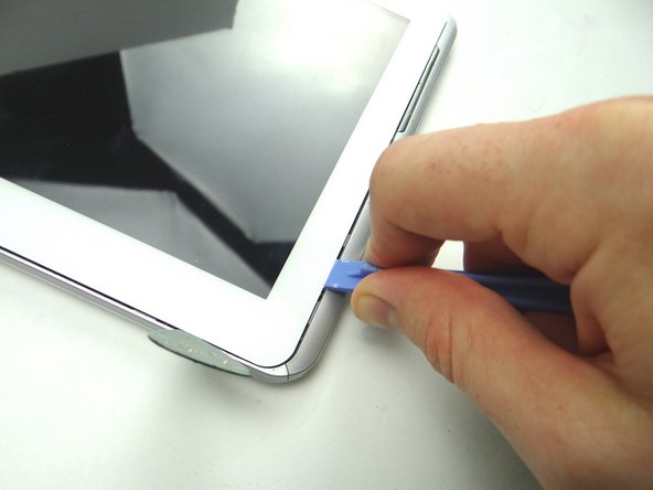
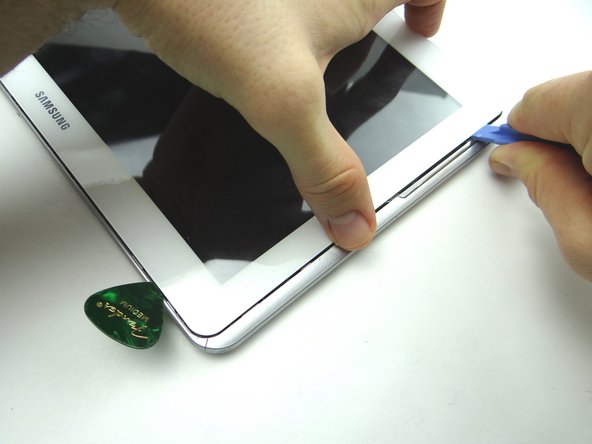
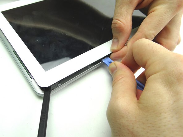
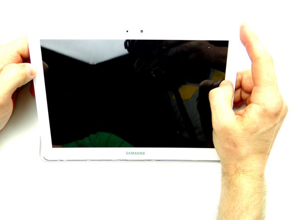
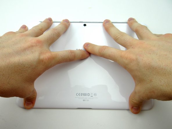
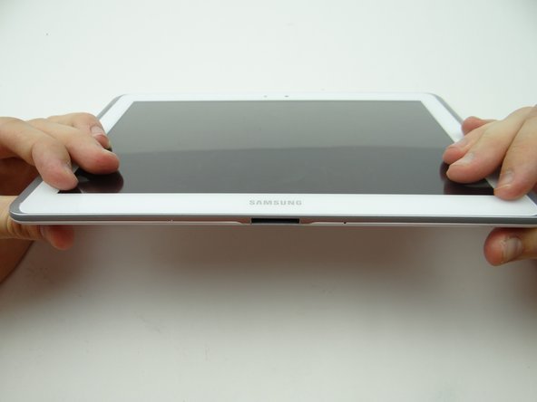
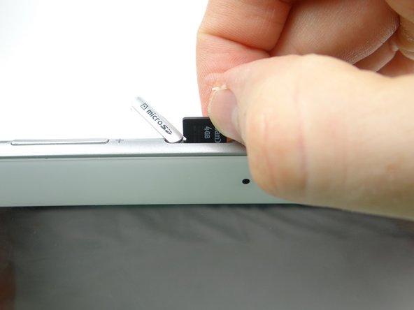
Picture 3: Insert a guitar pick to hold the right side open.
-
-
-
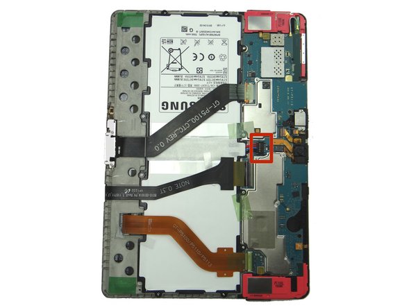
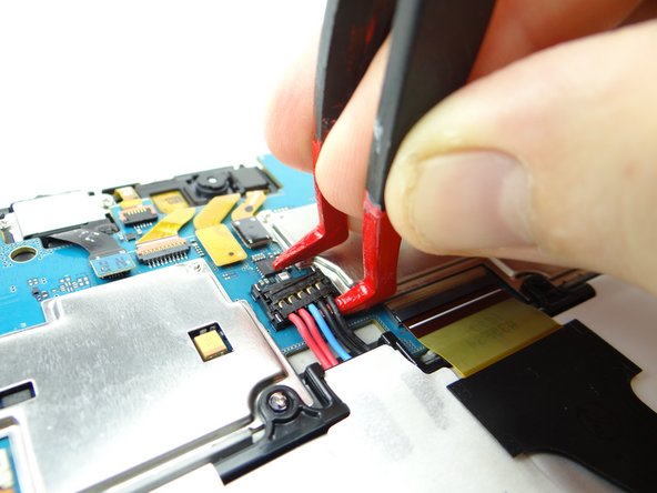
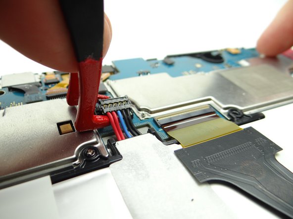
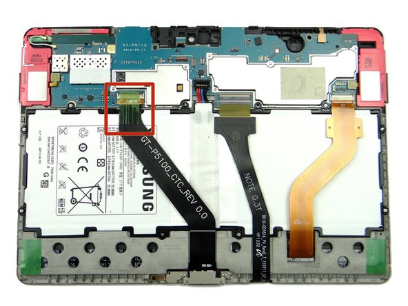
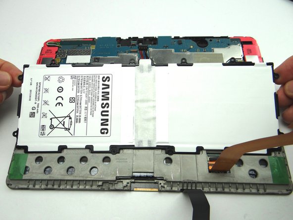
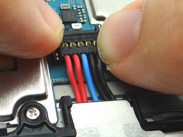
Battery cable head is fragile:
-
Use one prong of the plastic tweezers to wedge under the right side of the battery connector and pull it up slightly.
-
Lift battery connector straight up from the left side to dislodge it.
-
-
-
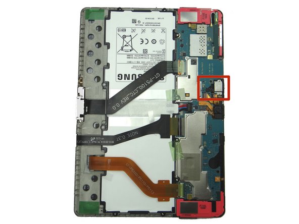
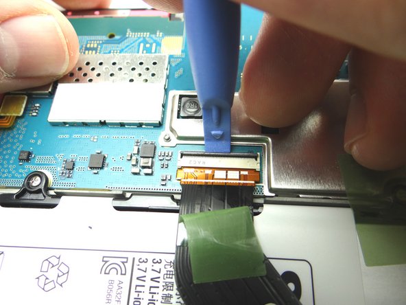
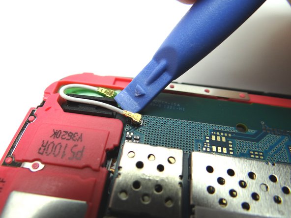
Remove the headset jack:
-
Use blue pry tool to disconnect headset jack cable.
-
Remove two 3.0 mm #00 Phillips screws from the headset jack. Place screws in SLOT 1.
-
-
-
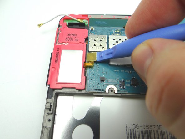
Use blue pry tool to open ZIF connector holding the infrared sensor cable.
-
With the ZIF connector open, use your finger to pull the cable free.
-
-
-
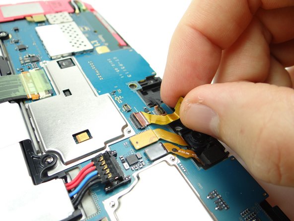
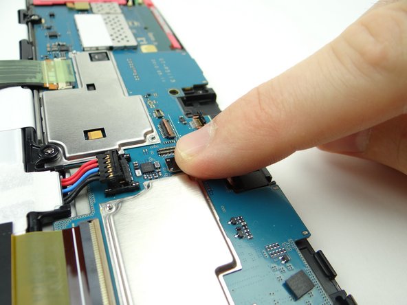
Picture 1: Use the blue pry tool to push ZIF connector open.
-
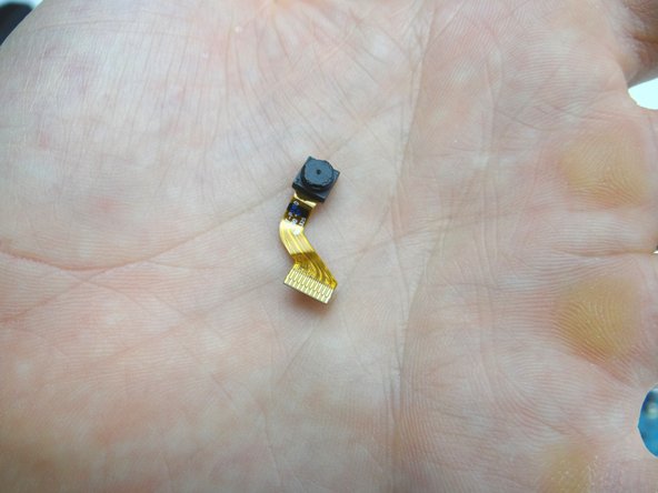
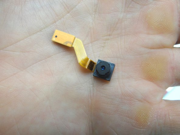
Picture 2: Lift front camera from its socket, then away from the ZIF connector.
-
Picture 3: Place in COMPARTMENT C.
-
-
-
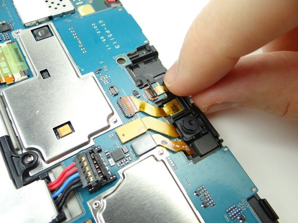
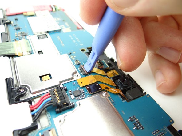
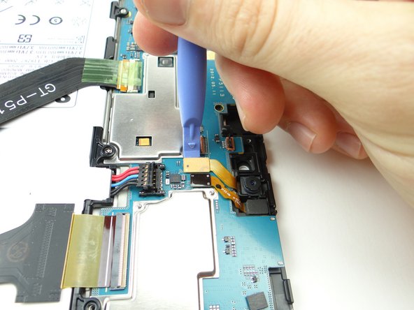
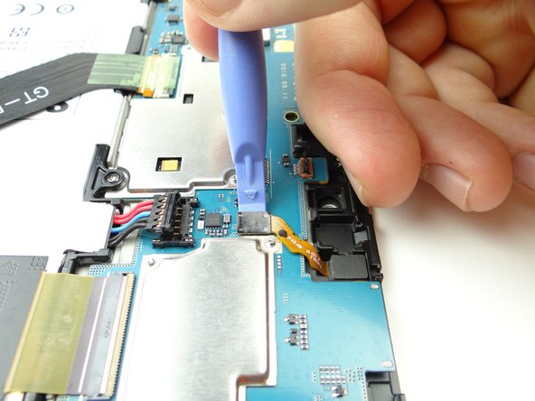
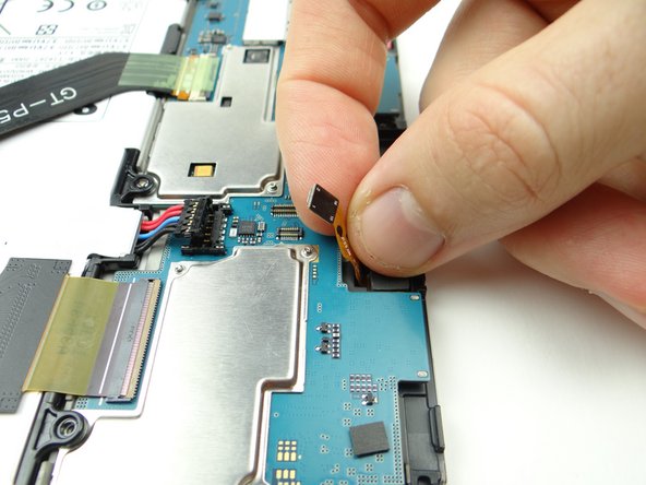
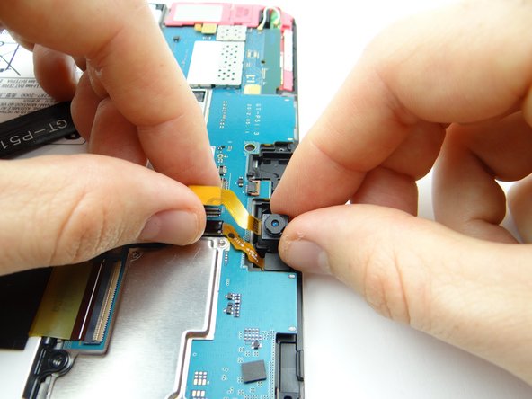
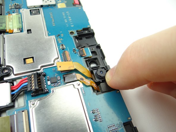
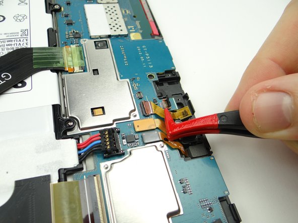
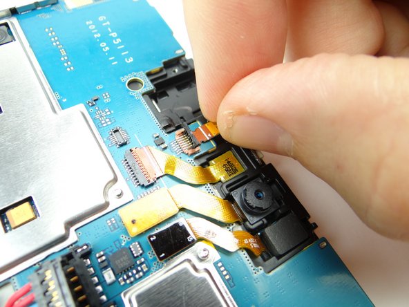
Use blue pry tool to disconnect rear camera.
-
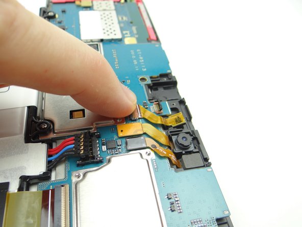
Remove rear camera and place in COMPARTMENT D.
-
-
-
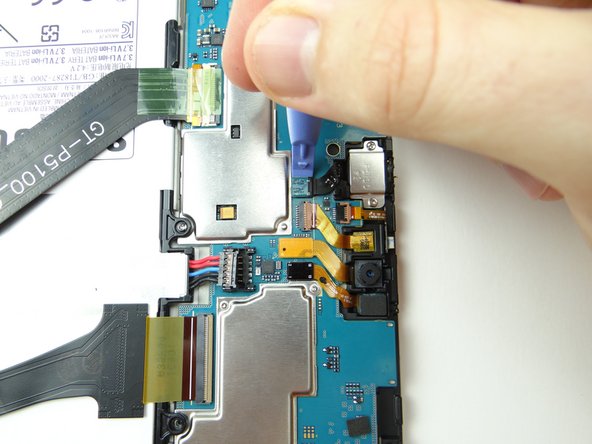
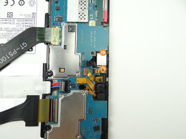
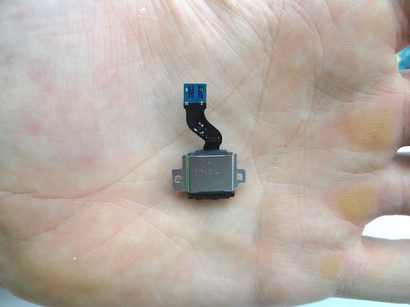
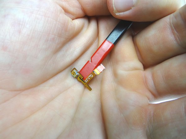
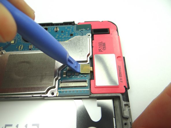
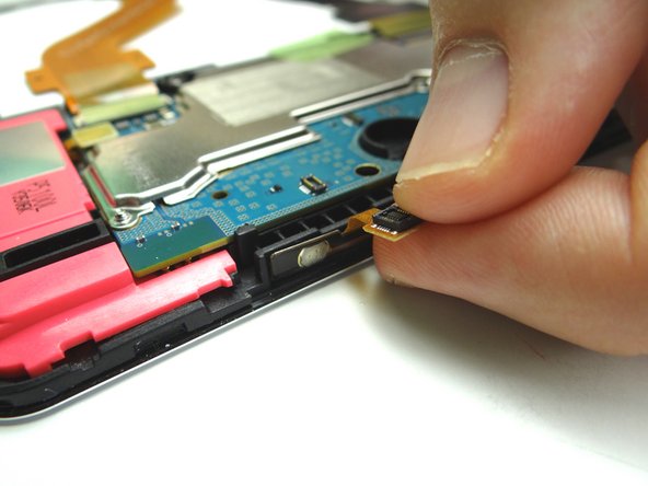
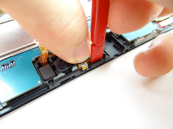
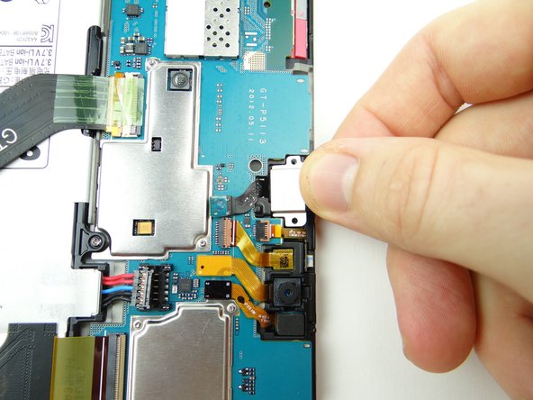
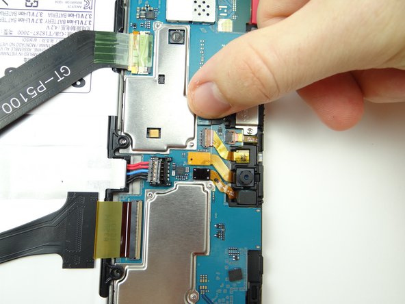
Picture 1: Use blue pry tool to disconnect sensor cable.
-
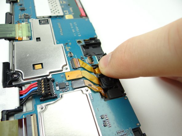
Picture 2: Pinch cable as close to sensor as possible and gently pull it free.
-
Picture 3: Place sensor in COMPARTMENT D.
-
-
-
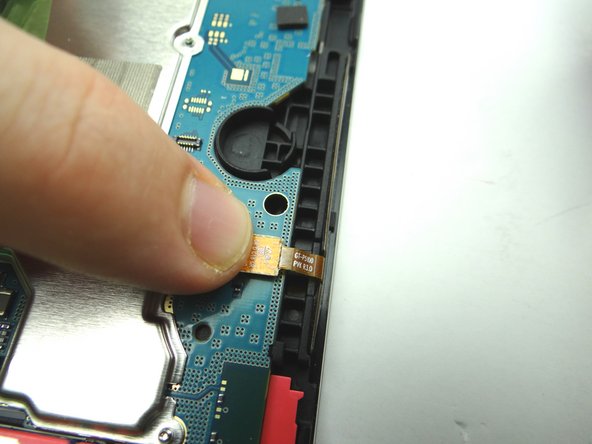
Picture 1: Use blue pry tool to disconnect vibrator cable.
-
Picture 2: Use curved-tip tweezers in the closed position to wedge underneath the vibrator. Pry it up slightly then grab it with your fingers to finish removing it.
-
Picture 3: Place it in COMPARTMENT F.
-
-
-
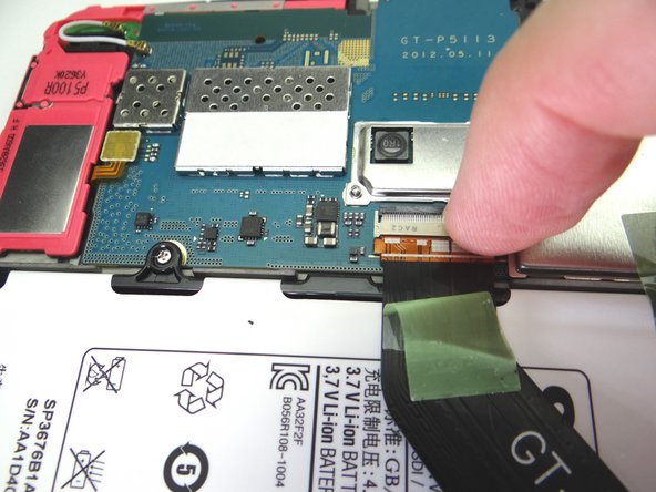
Picture 1: Use blue pry tool to disconnect power / volume buttons cable.
-
Adhesive holds the power & volume buttons cable in place:
-
Picture 2: Use the flat end of the spudger to separate the cable from the frame.
-
Picture 3: Place power & volume buttons cable in COMPARTMENT E.
-
-
-
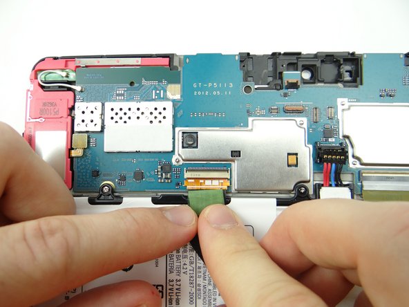
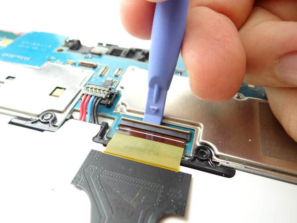
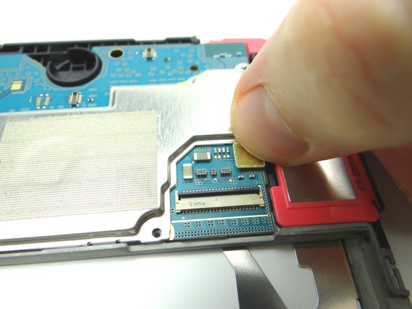
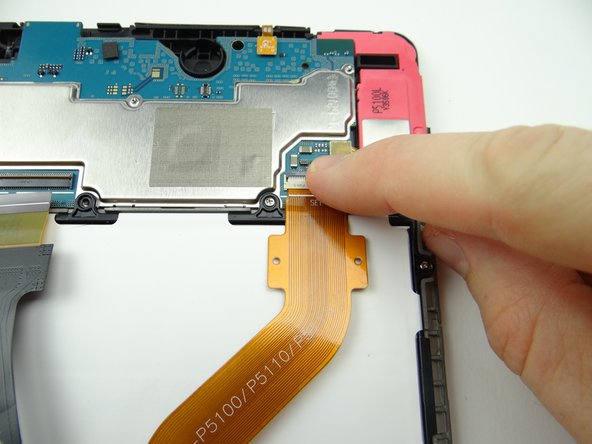
Picture 1: Peel tape up from connector and fold it back. Don't discard it - leave it attached to the cable.
-
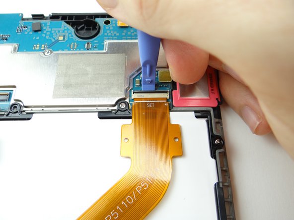
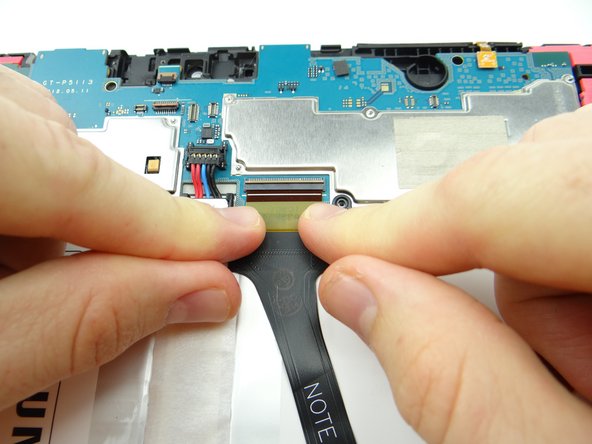
Picture 2: Use blue pry tool to lift ZIF connector black bar into open position.
-
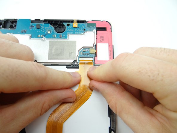
Picture 3: Slide cable out with your fingers.
-
-
-
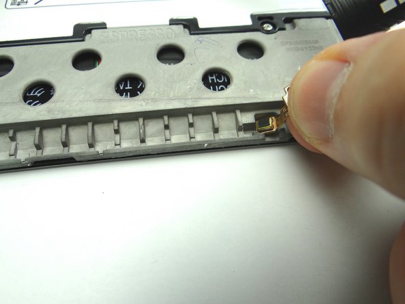
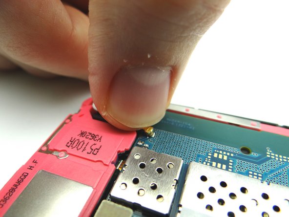
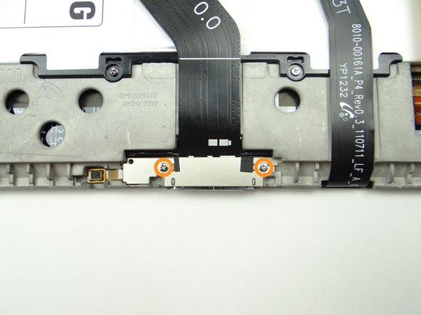
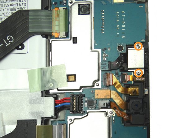
Picture 1: Remove two 2.9 mm #00 Phillips screws securing charging port. Place in SLOT 2.
-
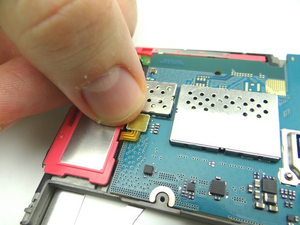
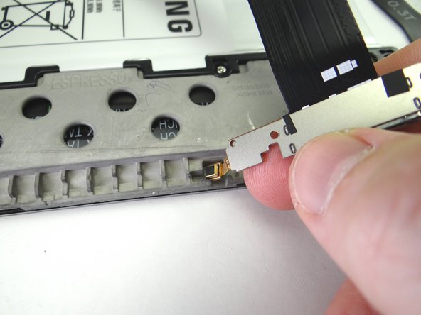
Adhesive holds the microphone (attached to the charging port) in place:
-
Pictures 2: Pull up the right side of the charging port until the microphone starts to stick. Pinch the microphone with your fingers and peel it up.
-
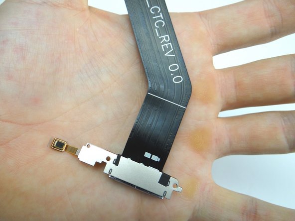
Picture 3: Place charging port / microphone assembly in ZONE V.
-
-
-
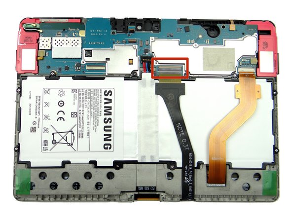
Use blue pry tool to lift the cream-colored digitizer ZIF connector bar into open position.
-
Slide cable out with your fingers.
-
-
-
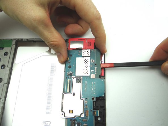
Picture 1: Use blue pry tool to disconnect antenna from logic board. Leave antenna connected to the loudspeaker.
-
Picture 2: Use blue pry tool to disconnect loudspeaker from logic board.
-
Picture 3: Use blue pry tool to disconnect opposite loudspeaker from logic board.
-
-
-
The logic board should come up easily:
-
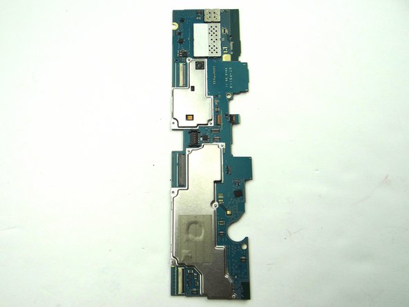
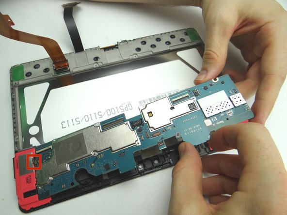
Picture 1: Wedge the flat end of the spudger under the top edge of the logic board as shown. Pry up just enough to pinch the logic board with your fingers.
-
Picture 2: Carefully continue lifting logic board away from the front panel.
-
Picture 3: Place in ZONES I & II.
-
-
-
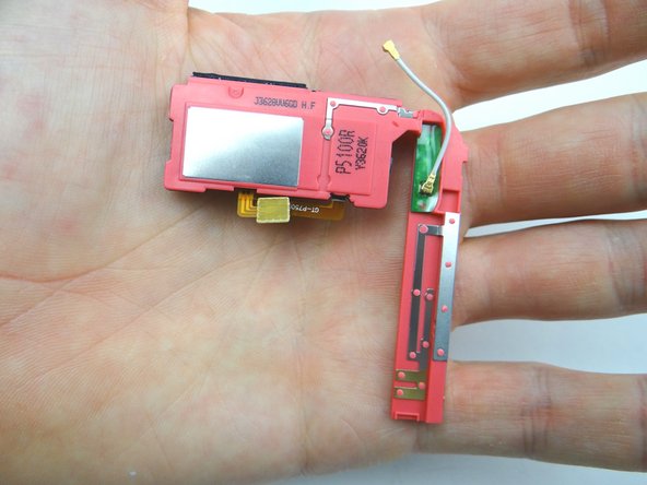
Wedge flat end of spudger under corner of loudspeaker with the antenna. Pull up with your hands at the same time.
-
Place in sandbox.
-
-
-
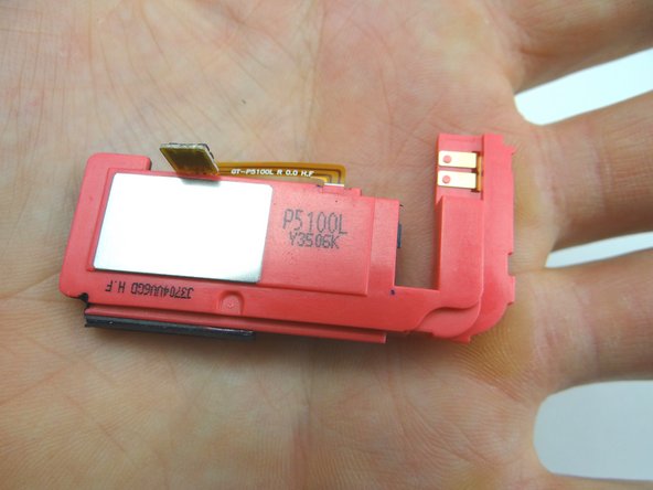
Wedge flat end of spudger under corner of loudspeaker without antenna. Pull up with your hands at the same time.
-
Place in sandbox.
-
-
-
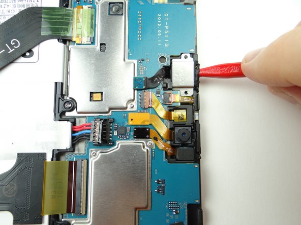
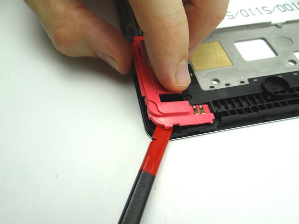
Replace loudspeaker without antenna:
-
Set under ledge (red square) then push into place.
-
-
-
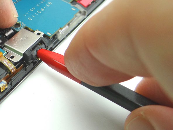
Replace loudspeaker with antenna:
-
Seat under ledge (red square) then push into place.
-
-
-
Picture 1: Retrieve logic board from ZONES I & II.
-
Pictures 2 & 3: Seat logic board. Make sure speaker cables and antenna don't get trapped underneath the board.
-
-
-
From ZONE V, replace charging port cable & microphone:
-
Picture 2: Seat microphone first then charging port.
-
Picture 3: Replace two 2.9 mm #00 Phillips screws securing charging port from SLOT 2.
-
-
-
From COMPARTMENT E, replace power / volume buttons cable.
-
Push assembly firmly back into place to adhere to the frame.
-
Connect cable to logic board.
-
-
-
Seat MISSING vibrator from COMPARTMENT F.
-
Connect cable to logic board.
-
-
-
From COMPARTMENT D:
-
Push sensor back into its socket.
-
Connect sensor cable to logic board.
-
-
-
Replace rear camera from COMPARTMENT D:
-
Push camera into its socket.
-
-
-
Replace front-facing camera from COMPARTMENT C:
-
Use plastic tweezers or your fingers to push front-facing camera cable into open ZIF connector.
-
Close ZIF connector.
-
-
-
Picture 1: Replace infrared sensor from COMPARTMENT C. Use flat end of spudger to push infrared cable against the mid-frame wall.
-
Push cable into open ZIF connector.
-
Close ZIF connector.
-
-
-
Picture 1: Seat headphone jack from COMPARTMENT B.
-
Picture 2: Connect cable to logic board.
-
Picture 3: Replace two 3.0 mm #00 Phillips screws from the headset jack from SLOT 1.
-
-
-
Seat front panel on rear case, charging port first.
-
Push center clips into place.
-