Parts
No parts specified.
-
-
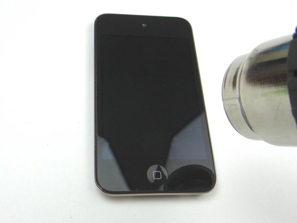
We provide two methods for removing the screen: one using a suction cup and another using the iSesamo opening tool. The suction cup method is preferred, but the iSesamo may be necessary if the screen is badly cracked.
-
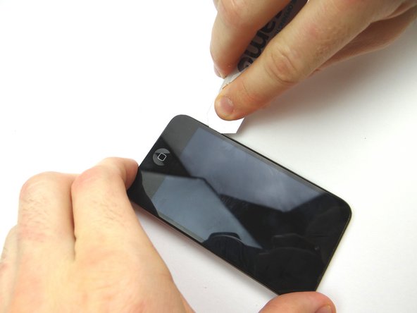
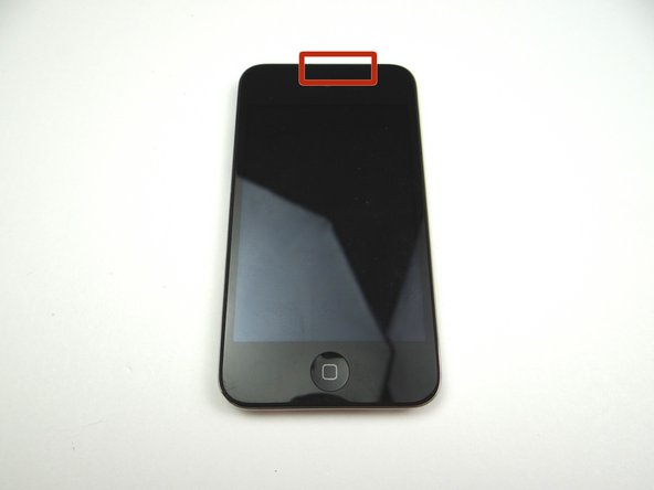
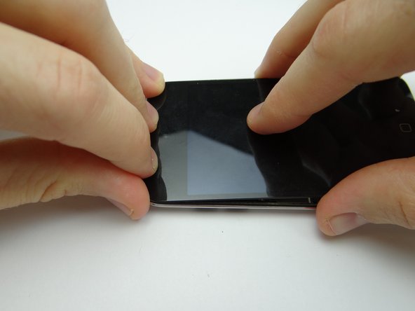
Picture 1: Place the suction cup on the screen just above the home button. Apply low-level heat (100° Celsius) around the perimeter of the iPod for 60 seconds. Heat the bottom edge for an additional 60 seconds.
-
The iPod may be hot to the touch.
-
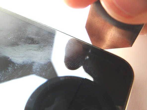
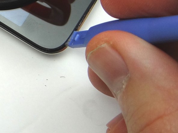
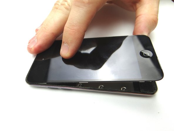
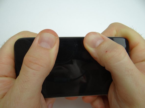
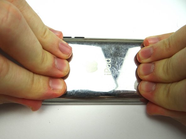
Pictures 2 & 3: Use the suction cup to pull the screen up just enough to wedge the blue pry tool between the screen and the rubber bezel encircling it.
-
Leave suction cup attached.
-
-
-
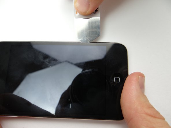
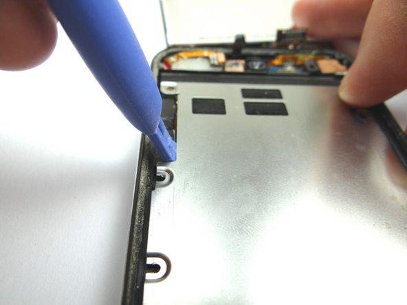
Picture 1: Wedge a guitar pick in the lower-right corner. Using the blue pry tool, work your way across the bottom edge of the iPod gently prying up as you go.
-
Picture 2: Wedge a guitar pick in the lower-left corner. Work your way up the left side with the guitar pick.
-
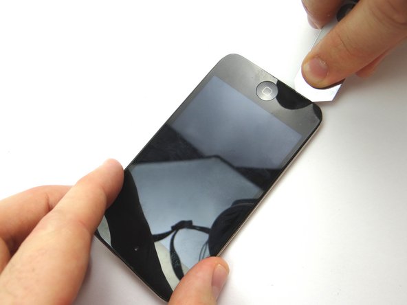
Picture 3: Gently pull up on the suction cup while using the blue pry tool to lift the lower-left corner. Repeat on the lower-right corner. Create just enough space to grab the screen with your fingers.
-
If you're unable to create suction, use the alternate method in the next two steps. Otherwise, skip the next two steps.
-
-
-
Picture 1: Apply low-level heat (100° Celsius) around the perimeter of the iPod for 60 seconds. Heat the bottom third of the iPod for an additional 60 seconds.
-
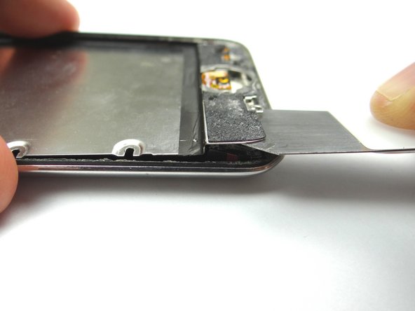
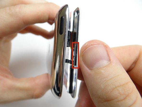
Picture 2: Insert iSesamo along the right edge, 1 inch from the bottom, at a 90 degree angle.
-
Make sure you push between the screen and the black rubber bezel (NOT between the bezel and rear case).
-
Picture 3: Pivot iSesamo to begin freeing the screen from the rear case. Work your way up the right edge with just the tip of the iSesamo as shown.
-
-
-
Picture 1: Wedge the blue pry tool between the screen and the rubber bezel encircling it.
-
Picture 2: Gently pry the bottom of the screen free from the rear case with your fingers.
-
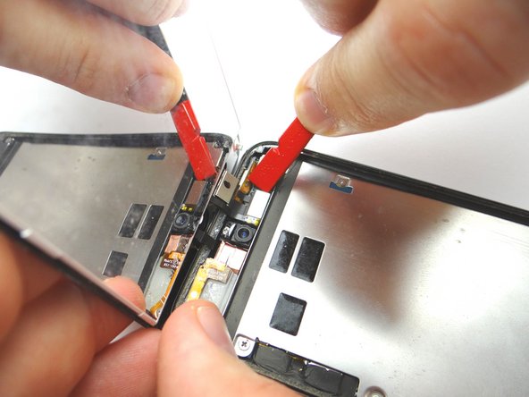
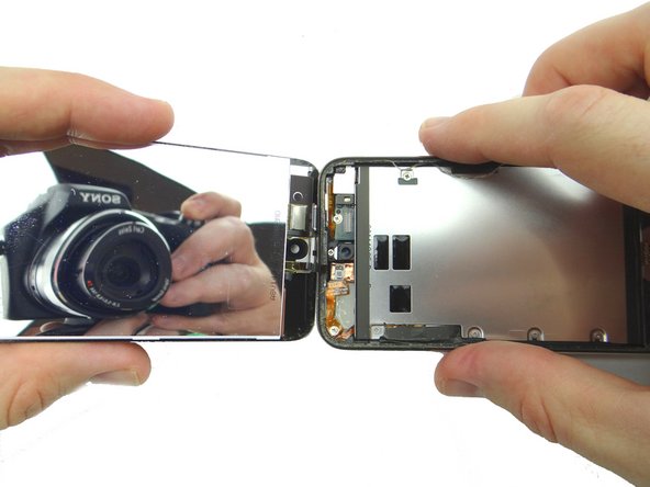
Picture 3: Open the display assembly to a 90 degree angle. Disconnect the LCD ribbon cable with the spudger.
-
-
-
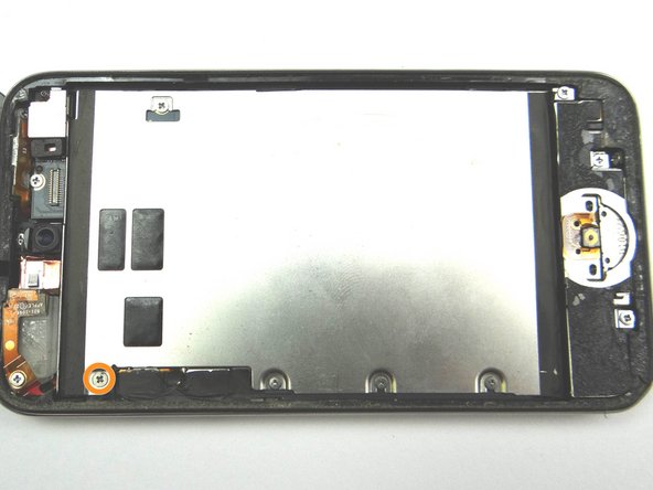
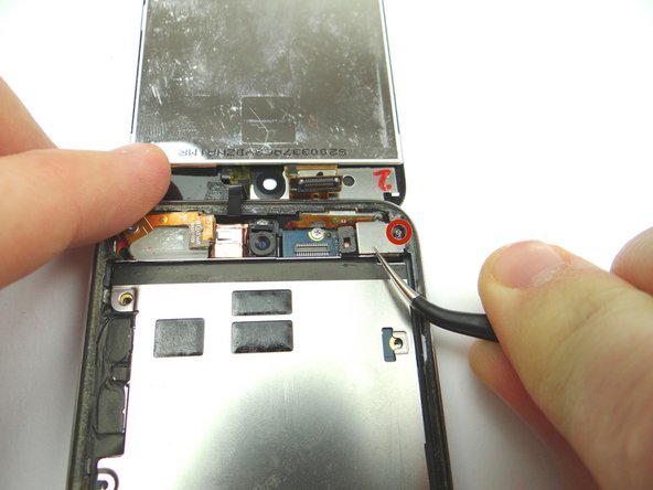
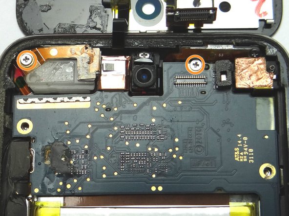
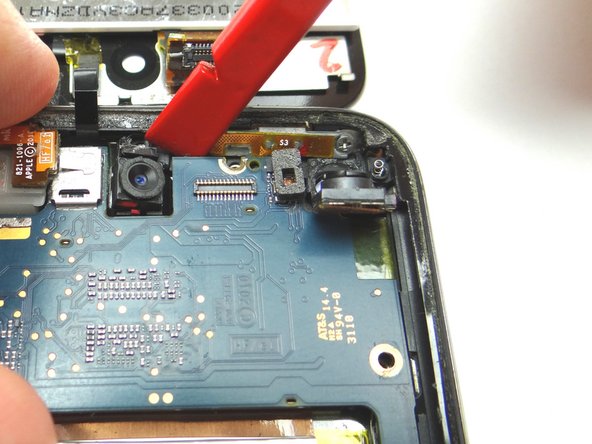
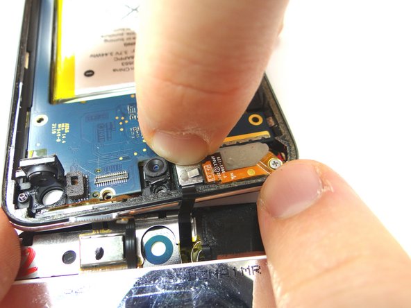
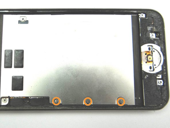
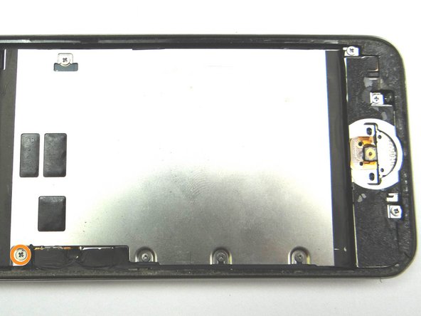
Picture 1: Remove two 2.3 mm Phillips screws and place into SLOT 7.
-
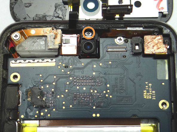
Picture 2: Remove one 2.0 mm Phillips screw and place into SLOT 8.
-
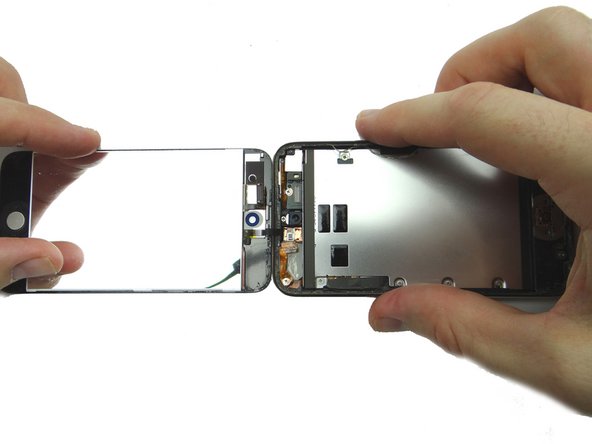
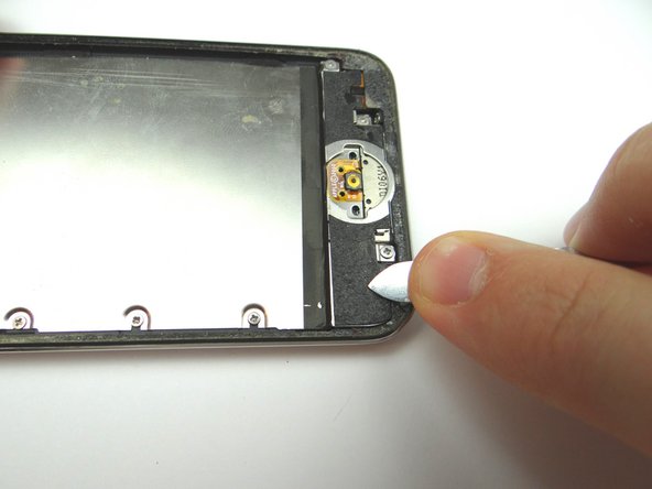
Picture 3: Use Black Spudger to lift rear camera until it's just above the logic board.
-
DO NOT ATTEMPT TO REMOVE THE REAR CAMERA!
-
-
-
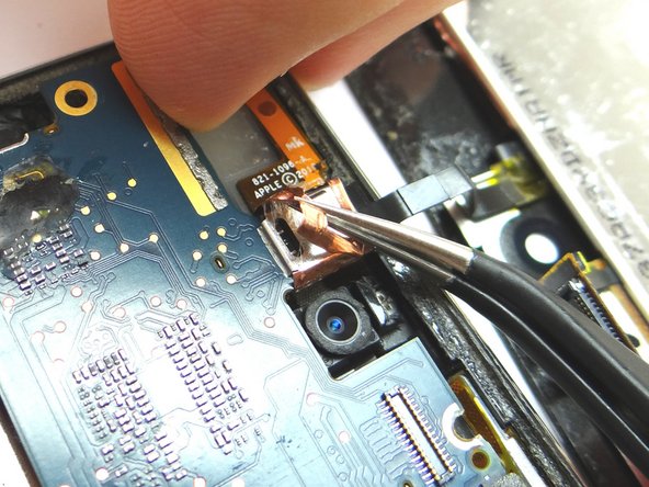
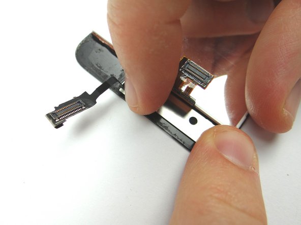
Picture 1: Use Curved Tip Tweezers to remove the copper tape wrapped around the digitizer's ribbon connector.
-
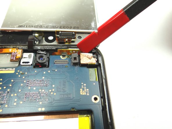
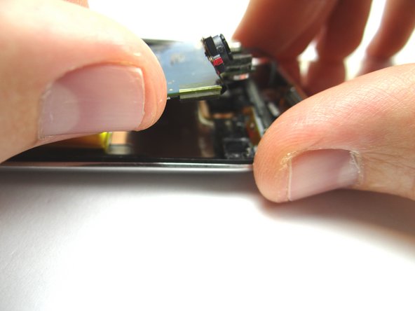
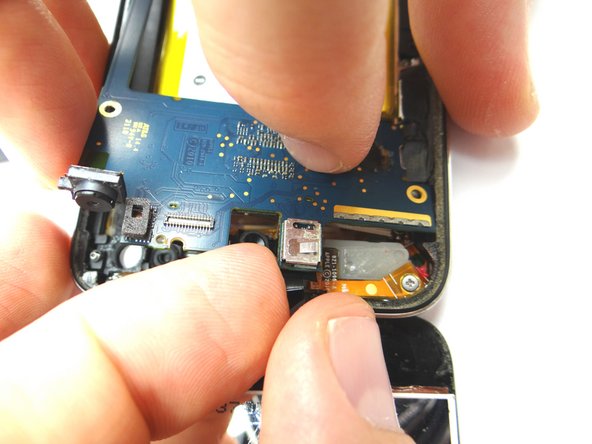
Picture 2: Place the Black Spudger to the right of the front-facing camera and pry the logic board up slightly.
-
Picture 3: Use your fingers to lift the top right of the logic board one inch above the rear case.
-
Ribbon cables are still attached - do not lift higher than an inch.
-
-
-
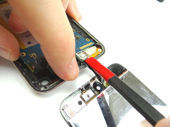
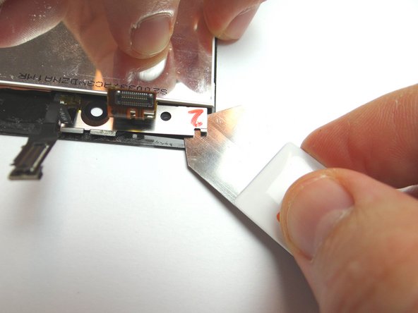
Picture 1: Use the Black Spudger to disconnect the digitizer ribbon underneath the logic board. Separate the display assembly from the rear case.
-
Never use metal tools on a working display:
-
Picture 2: Use iSesamo to dig up front-facing camera bracket. Place in COMPARTMENT A.
-
-
-
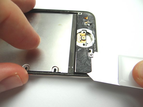
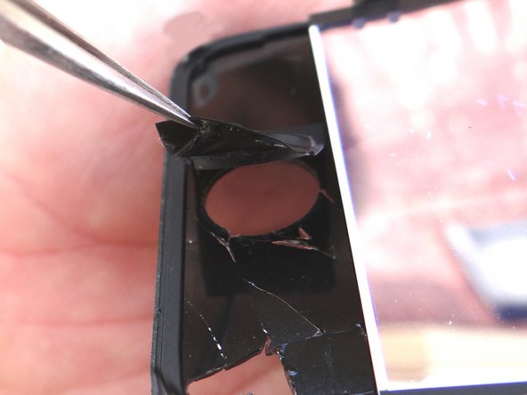
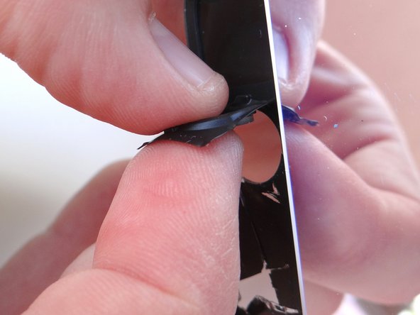
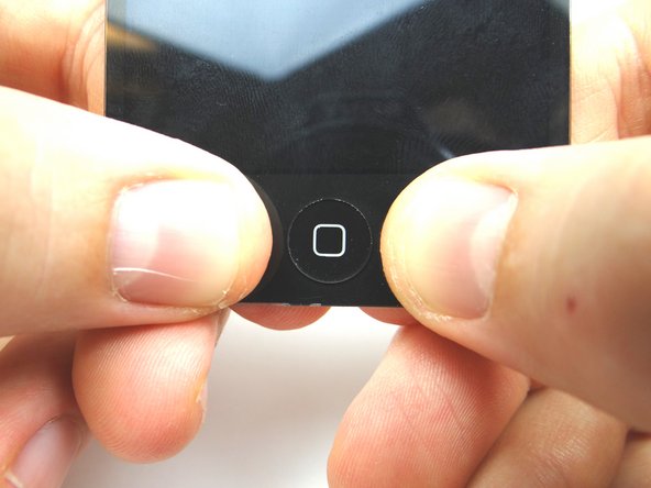
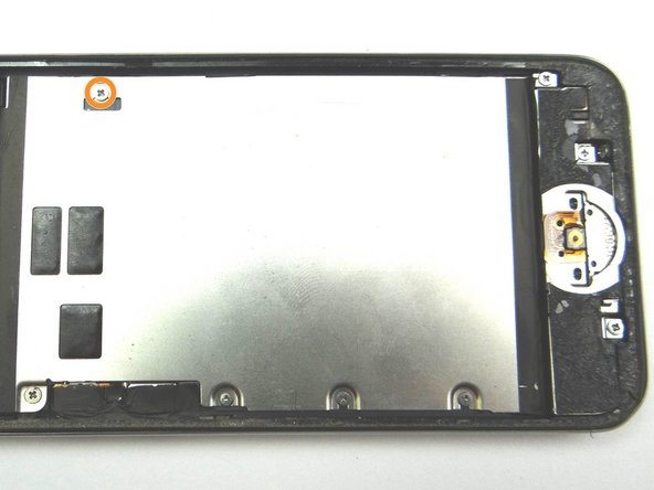
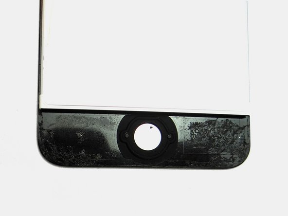
Picture 1: Place home button from COMPARTMENT B on the display assembly. Make sure the home button is aligned.
-
Picture 2: On the backside, press home button into place and smooth out any wrinkles in the rubber.
-
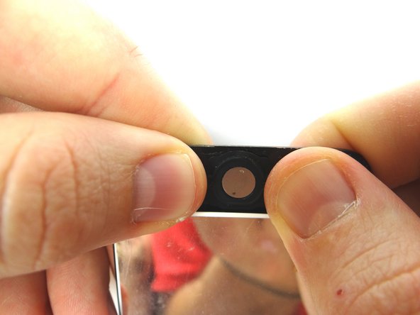
Picture 3: Place front-facing camera bracket from COMPARTMENT A on the display assembly.
-
If you're replacing the display, remove the protective film on the back of the LCD.
-
-
-
Picture 1: Align the digitizer ribbon connector with its socket on the underside of the logic board.
-
Picture 2: Push down on the logic board to seat the digitizer ribbon connector.
-
It may take several attempts to properly align and seat the connector. Don't force it - the digitizer connector should seat with minimal pressure. You'll feel a slight 'click' when it's properly seated.
-
-
-
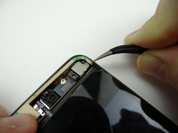
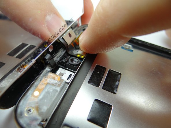
Picture 1: Use your finger to push the rear camera back into place.
-
-
-
Picture 1: Replace metal plate from ZONE I.
-
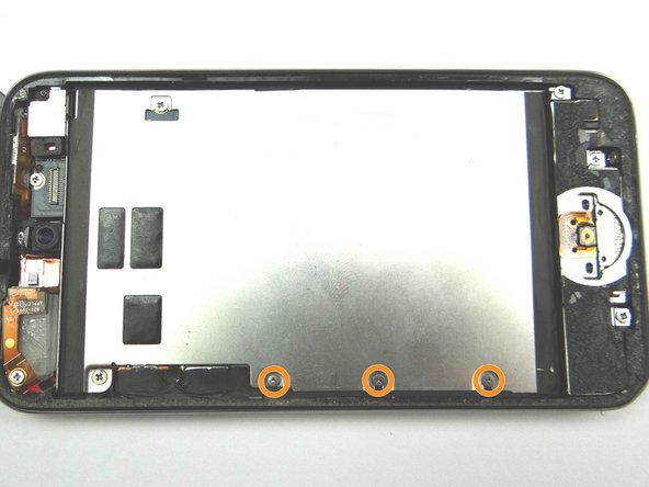
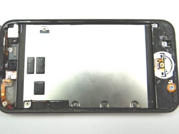
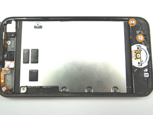
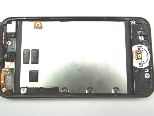
Picture 1: Replace one 2.3 mm Phillips screw from SLOT 5.
-
Picture 2: Replace two 3.0 mm Phillips screws from SLOT 4.
-
Picture 3: Replace one 3.5 mm Phillips screw from SLOT 3.
-
-
-
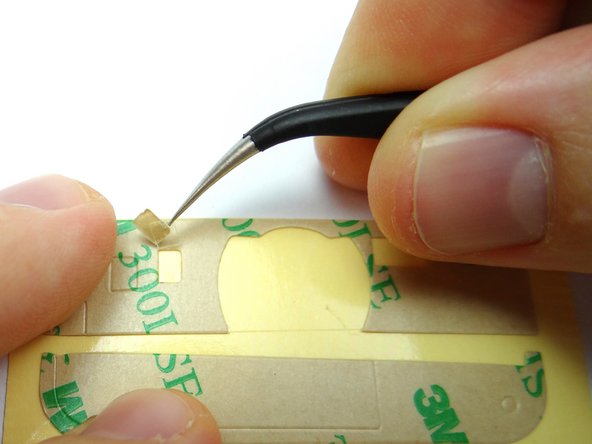
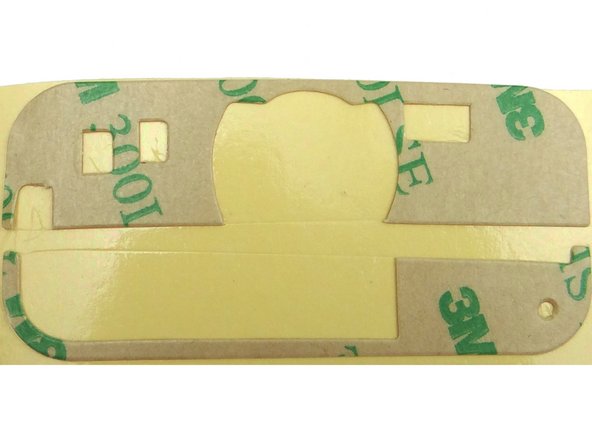
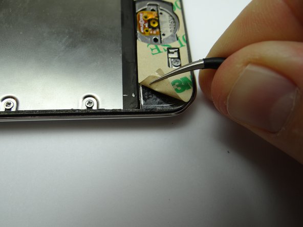
Picture 1: Place thin adhesive strip at the top of the rear case. Use your fingers to place the upper-left corner and curved-tip tweezers to place the upper-right corner. Peel off the paper backing.
-
Picture 2: Repeat with adhesive strip at the bottom, but don't close the iPod
-
Tuck in any part of the adhesive hanging over the edge of the rear case, if necessary.
-
-
-
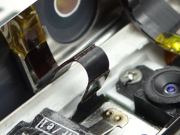
Picture 1: Make sure the digitizer cable folds into a 'Z' shape when closing the iPod.
-
Picture 2: Connect the LCD cable.
-
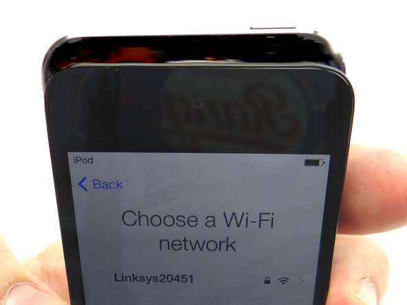
Picture 3: Power up and test the LCD and digitizer while holding the front panel away from the adhesive on the rear case.
-
After reassembling an iPod, it is common to see lines down the LCD or a white screen. Try turning it off and back on. If that doesn't work, you may have to perform a soft reset. (Press and hold power and home buttons simultaneously for ten seconds). If issues with the LCD persist, try re-seating the LCD cable.
-
-
-
Picture 1: Make sure the clips on the underside of the display, near the top, seat underneath the lip on the rear case.
-
Picture 2: Slide the top edge of the display assembly into the rear case.
-
If any of the adhesive is sticking out between the bezel and the digitizer, use the iSesamo to tuck it underneath the display assembly.
-
Press top firmly into place. Press bottom of the screen firmly into place.
-
Picture 3: Using light pressure, run your fingers up and down the left and right edges of the iPod to ensure the new display sits flush against the rear case.
-