-
-
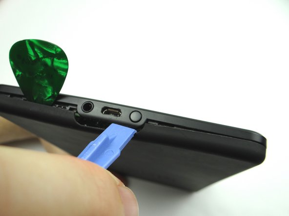
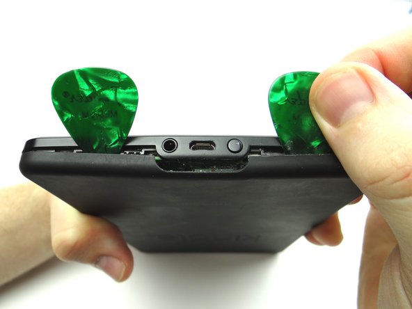
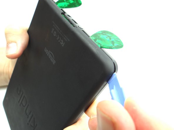
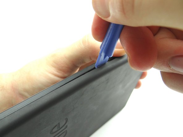
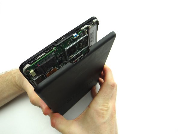
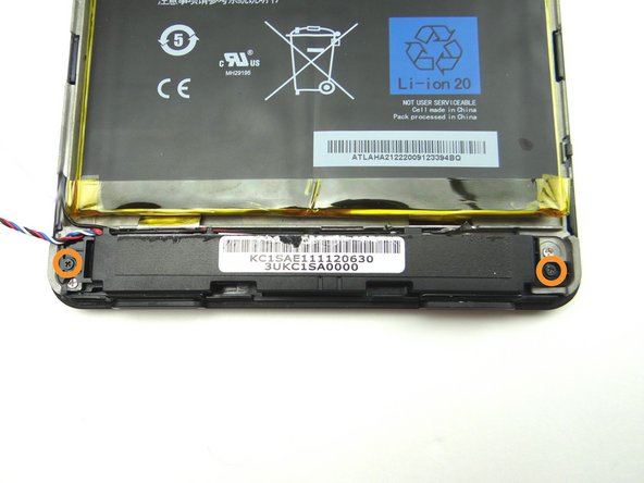
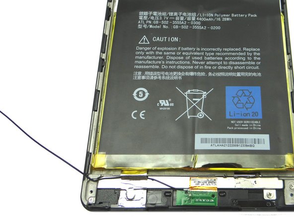
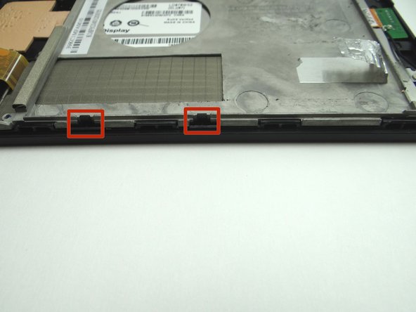
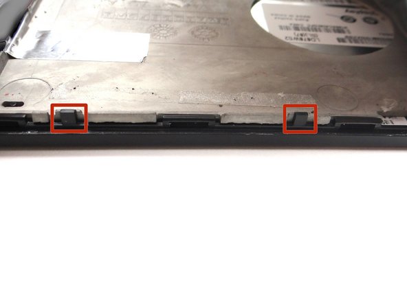
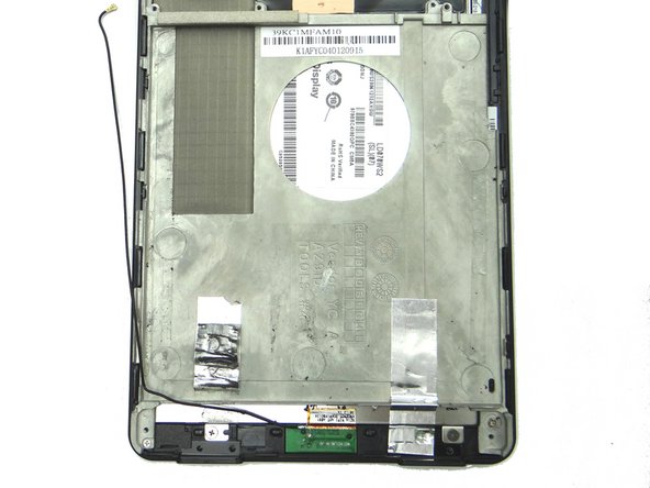
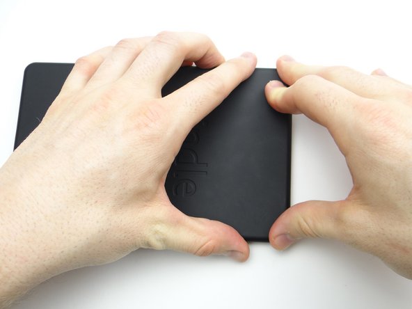
In the next few steps, you'll be opening the Kindle by freeing the clips marked in Picture 2.
-
-
-
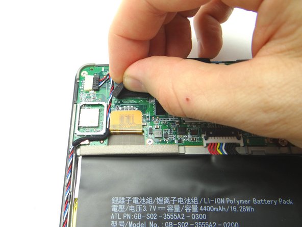
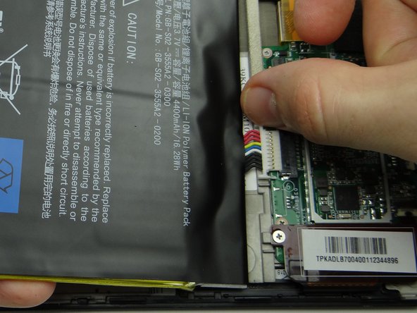
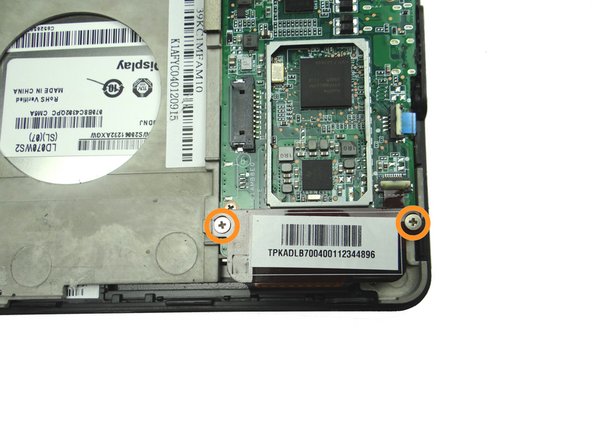
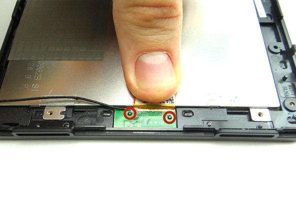
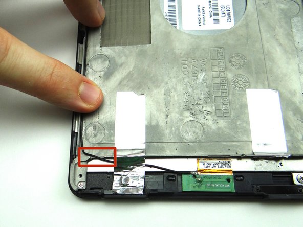
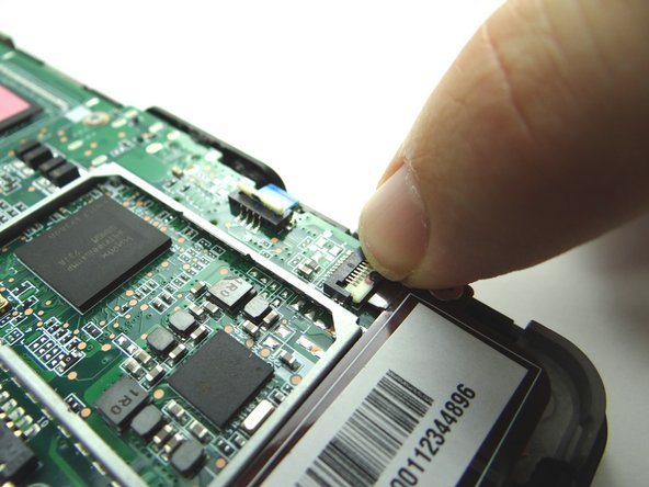
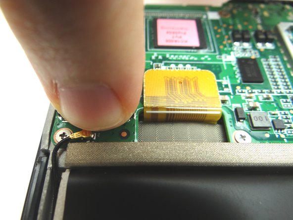
Picture 1: Peel up foam tape covering the speaker connector. Place in COMPARTMENT A.
-
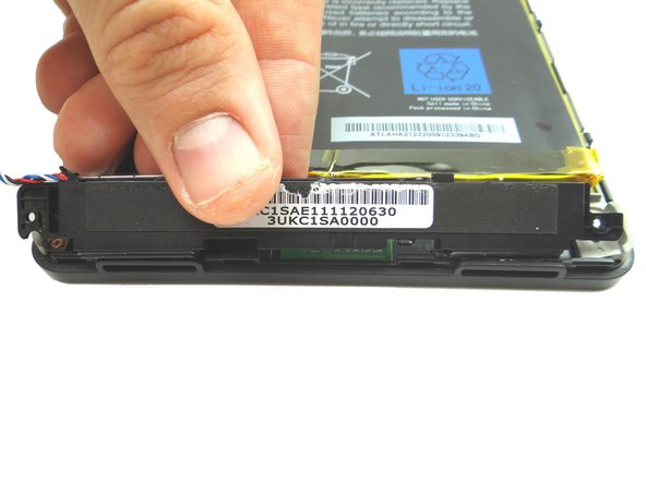
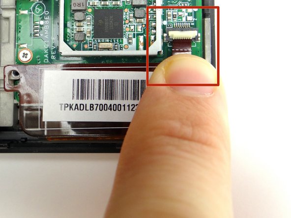
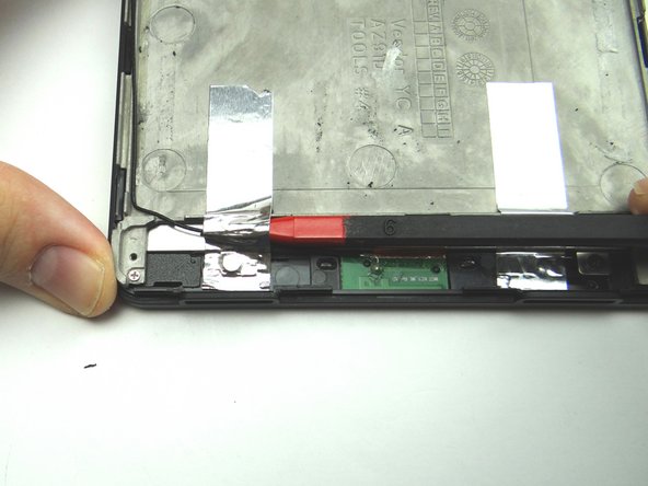
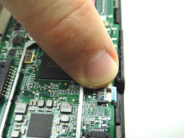
Picture 2: Wedge your fingers in the notches between the black speaker cable head and the white speaker connector. Pull the black speaker cable head free.
-
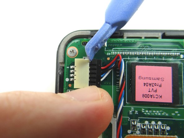
Use a blue pry tool if you can't fit your fingers in the notches.
-
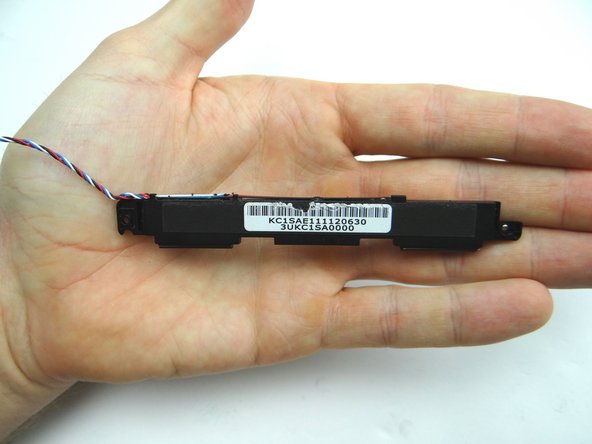
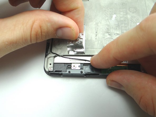
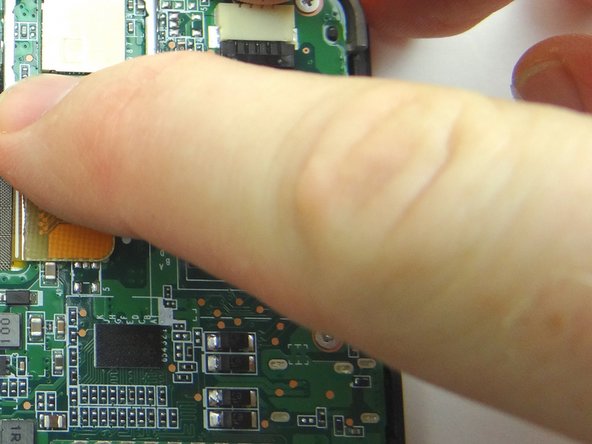
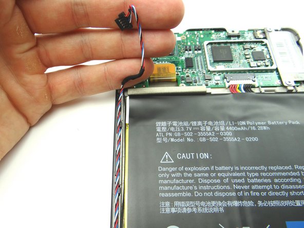
Picture 3: Unthread the speaker cable.
-
-
-
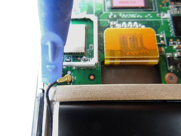
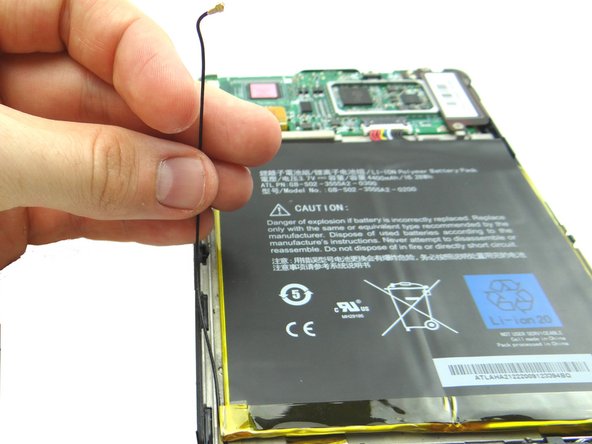
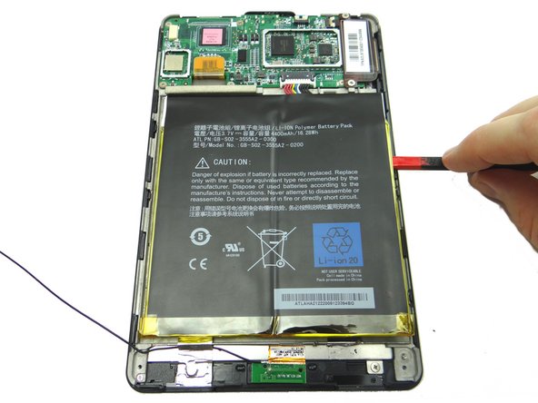
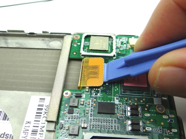
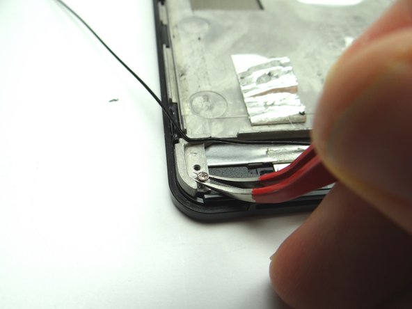
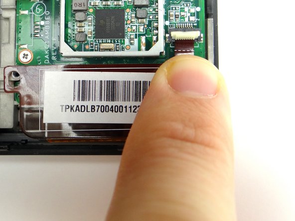
Use the blue pry tool to disconnect the antenna cable head.
-
Unthread antenna cable, but don't try to remove it.
-
-
-
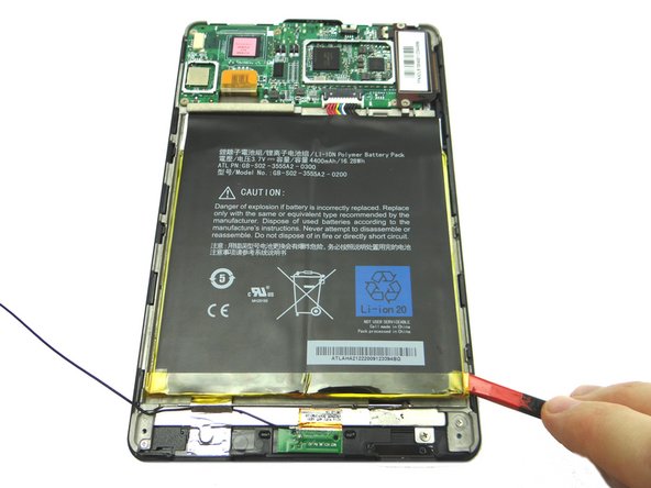
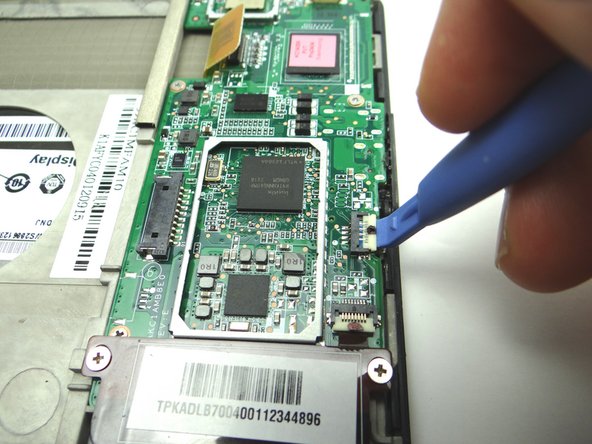
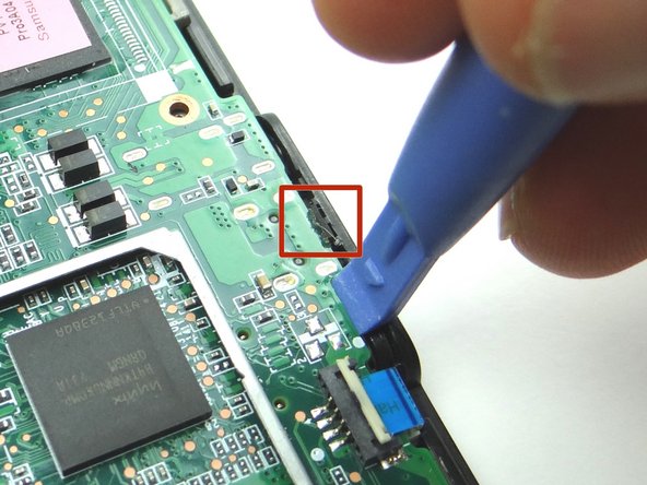
Picture 1: Use a wide blue pry tool to disconnect the LCD cable.
-
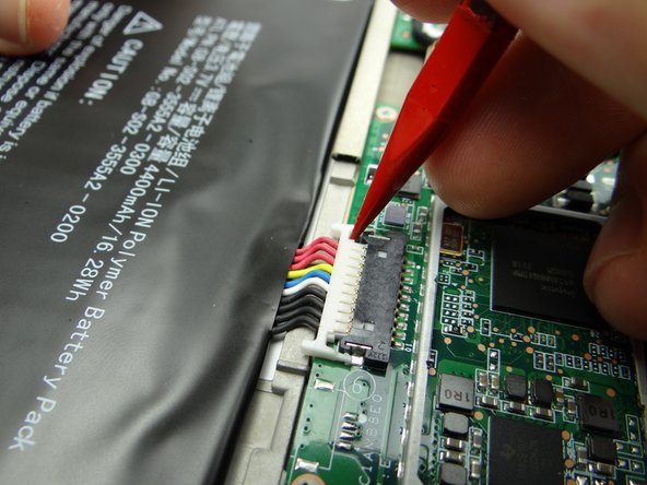
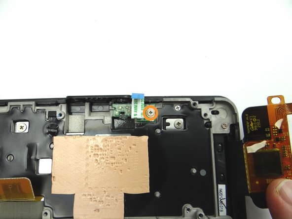
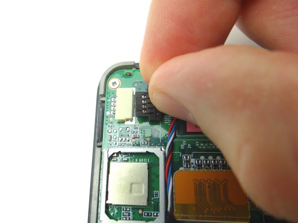
Picture 2: Open the ZIF connector securing the power button cable.
-
Picture 3: Open the ZIF connector securing the digitizer cable.
-
-
-
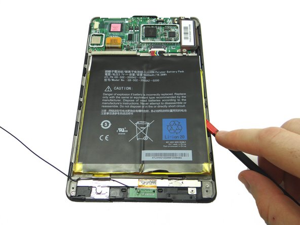
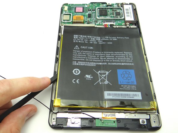
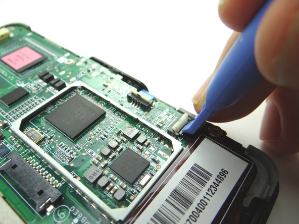
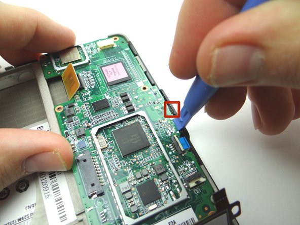
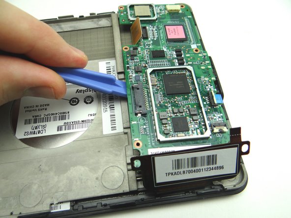
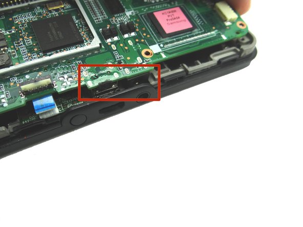
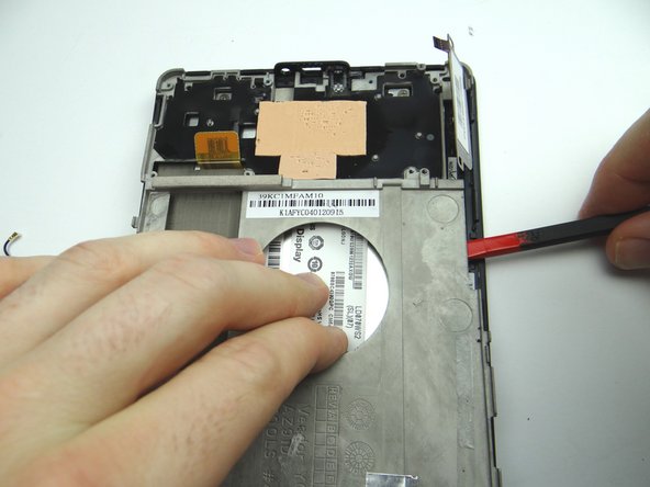
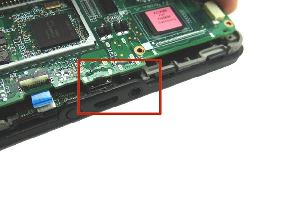
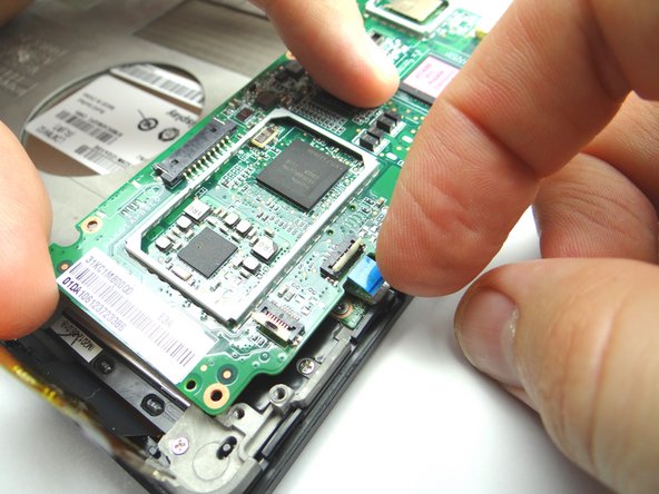
Pictures 1 & 2: Wedge the blue pry tool between the logic board and front panel exactly where shown. Pry just enough to pivot the logic board around the notch in the red square.
-
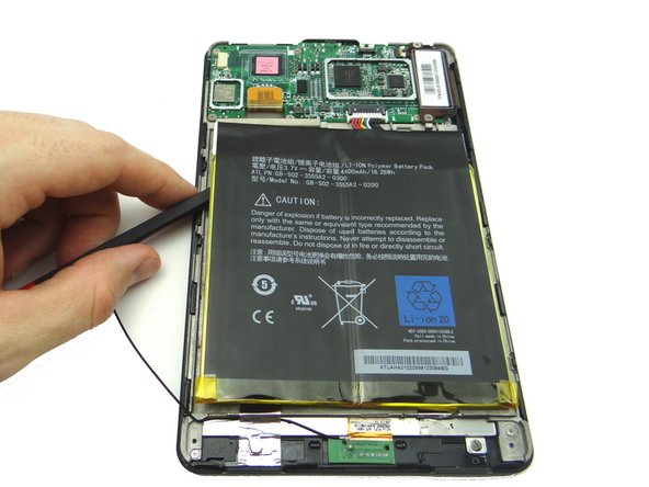
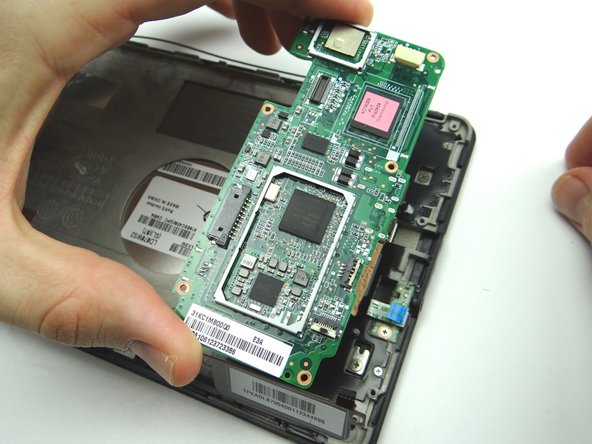
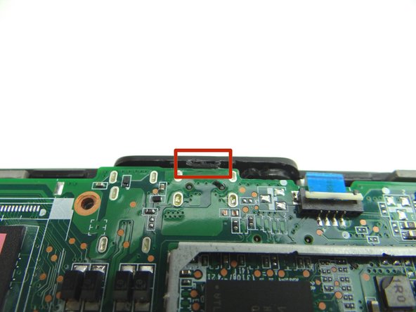
Picture 3: The bottom of the logic board is lightly adhered to the mid-plate. Wedge the wide blue pry tool exactly where shown. Gently twist counter-clockwise to lift the bottom of the board.
-
-
-
Remove the 2.5 mm Phillips scew securing the power button cable. Place screw in SLOT 4.
-
Peel up power button cable with your fingers and place in COMPARTMENT B.
-
-
-
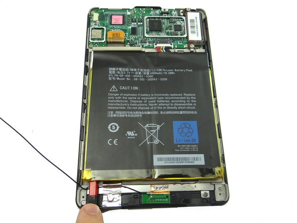
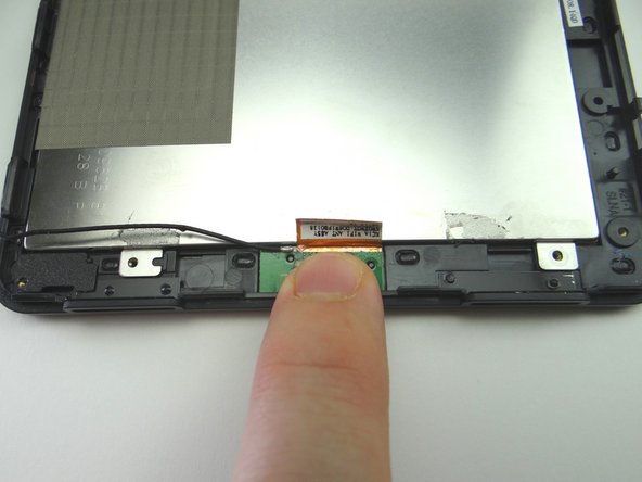
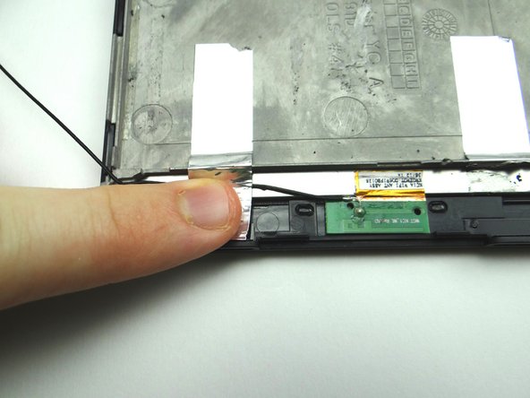
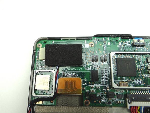
Use the pointed end of the spudger to peel up silver tape securing antenna cable.
-
Fold the tape out of the way.
-
-
-
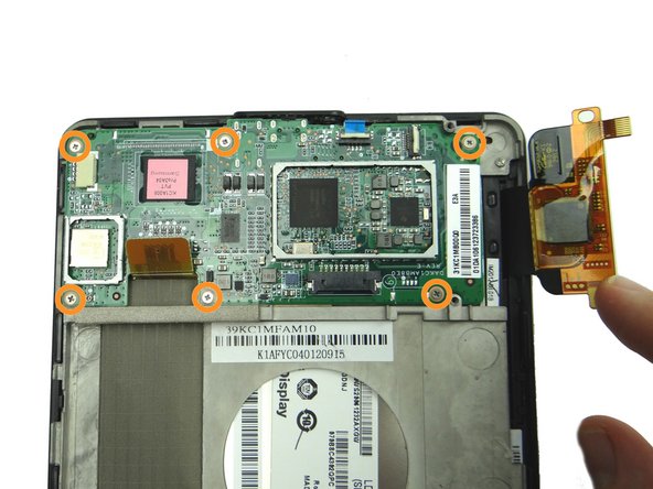
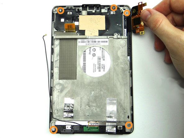
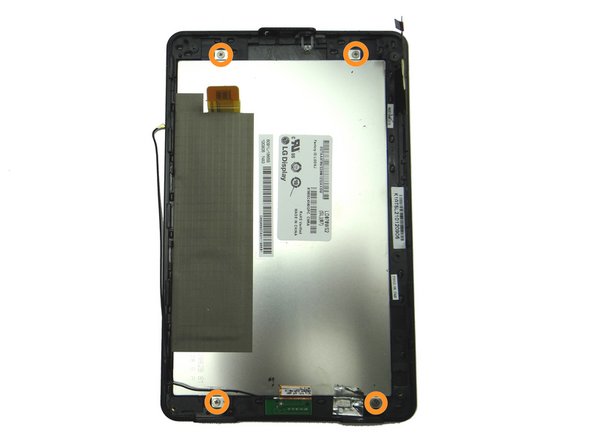
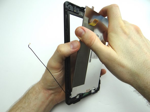
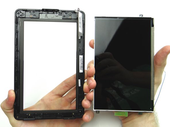
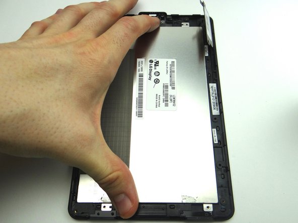
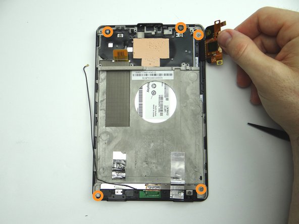
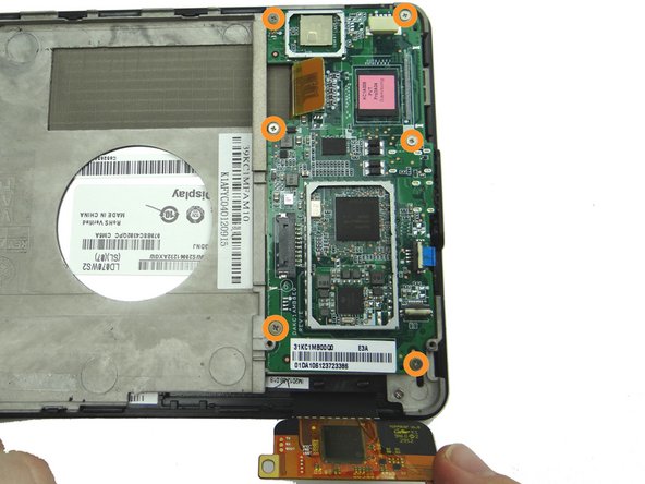
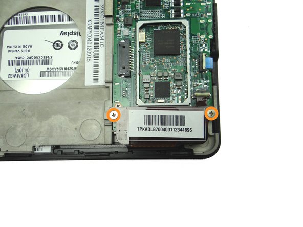
Remove four 2.4 mm Phillips screws holding the LCD to the front glass frame. Place in SLOT 6.
-
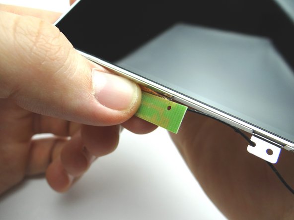
Separate the LCD from the front glass.
-
-
-
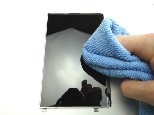
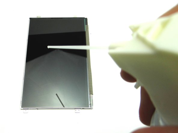
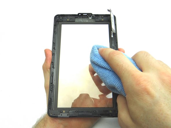
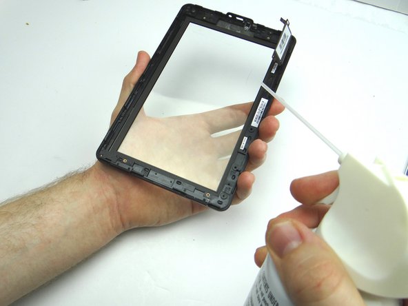
Check the LCD for fingerprints or particulates. If necessary, clean with a chamois cloth and dust-off.
-
-
-
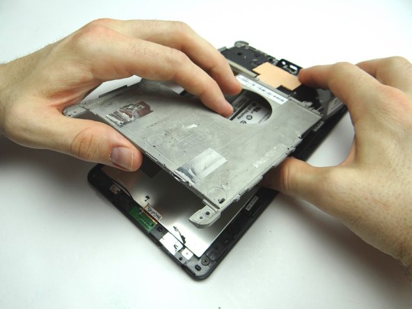
From ZONE V, seat mid-plate on front panel.
-
Make sure antenna cable is out of the way.
-
-
-
Replace power button cable from COMPARTMENT B.
-
From SLOT 4, replace the 2.5 mm Phillips screw to secure the power button cable.
-
-
-
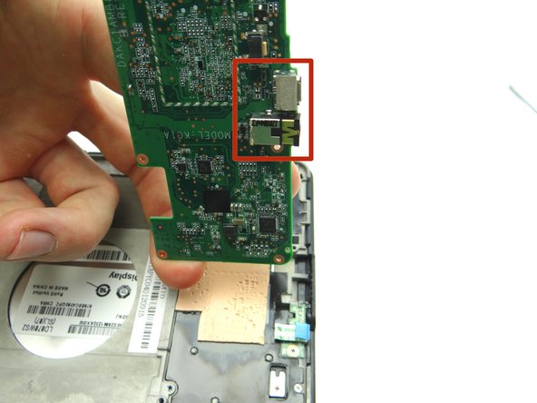
Replace logic board from ZONES II & III. Guide the charging port and headset jack in first:
-
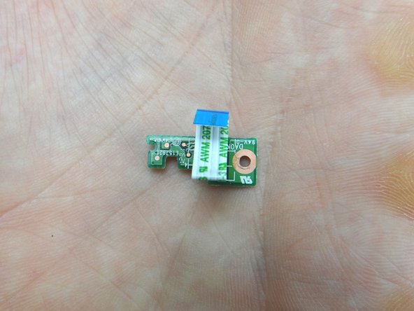
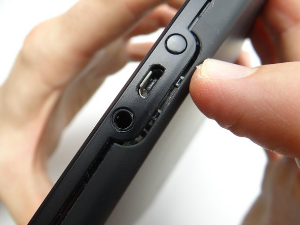
Picture 1: Shows the charging port and headset jack on the bottom of the logic board.
-
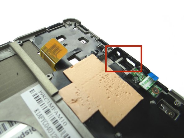
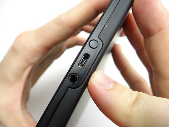
Picture 2: Shows the openings for the headset jack and charging port.
-
Picture 3: Guide the charging port and headset jack in.
-
Make sure the power button cable doesn't get stuck under the logic board.
-
-
-
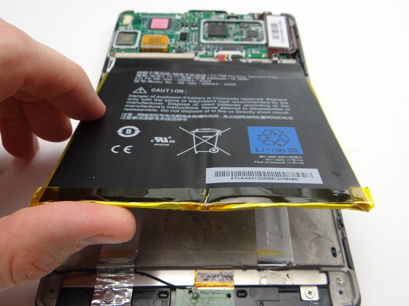
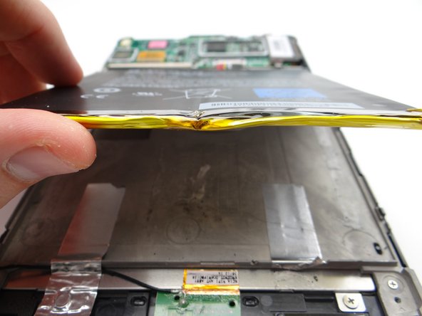
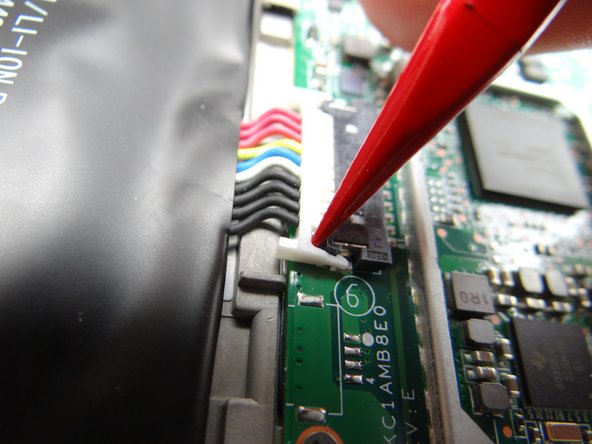
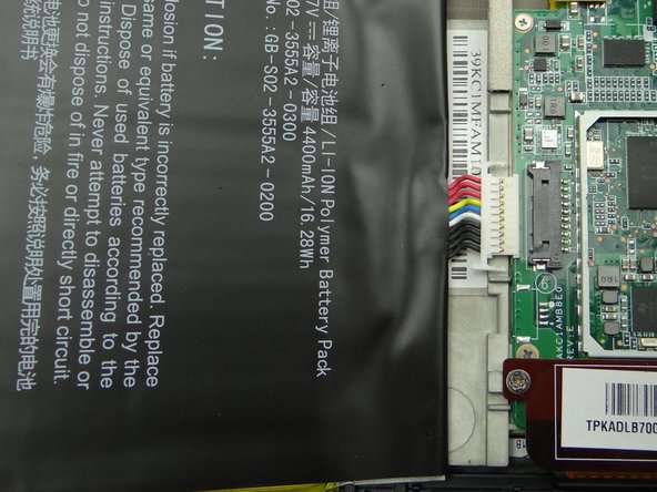
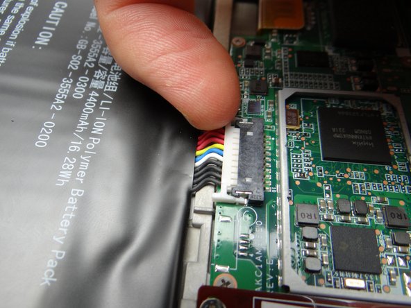
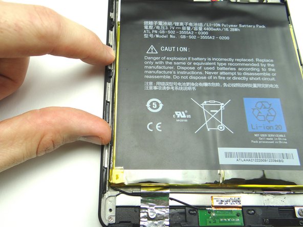
Seat the battery from ZONE V while guiding the battery connector into its socket.
-
Push connector in until it snaps into place.
-
-
-
Replace speaker assembly from ZONE I.
-
Replace two 3.3 mm Phillips #00 screws securing the speaker assembly from SLOT 1.
-
-
-
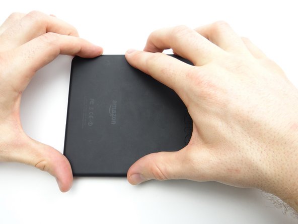
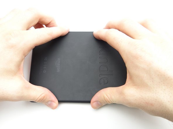
From ZONE V, secure the battery cover to the Kindle.
-
Start with the two tabs on either side of the charging port.
-