-
-
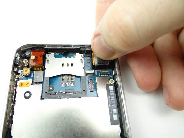
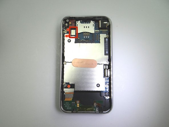
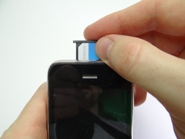
Remove the SIM Card Tray and SIM Card. Place in COMPARTMENT A
-
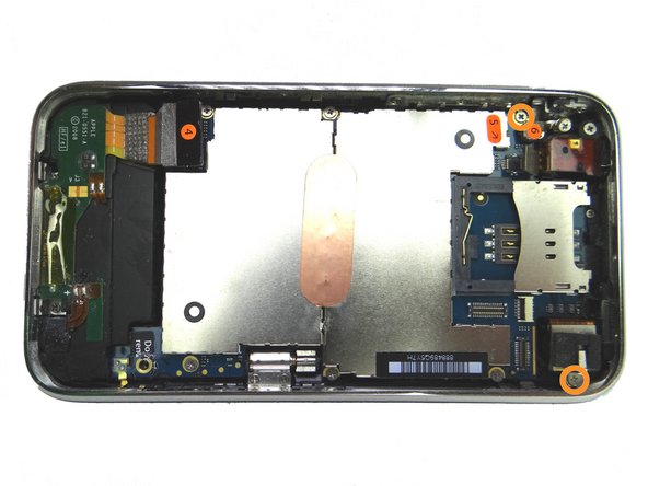
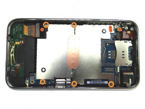
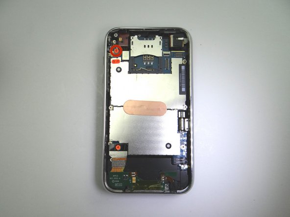
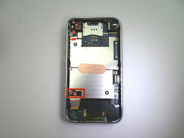
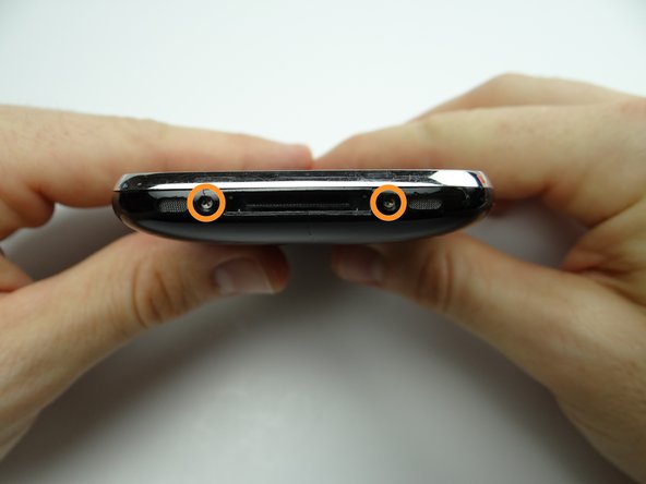
Remove two Phillips #00 screws and place in SLOT 1.
-
-
-
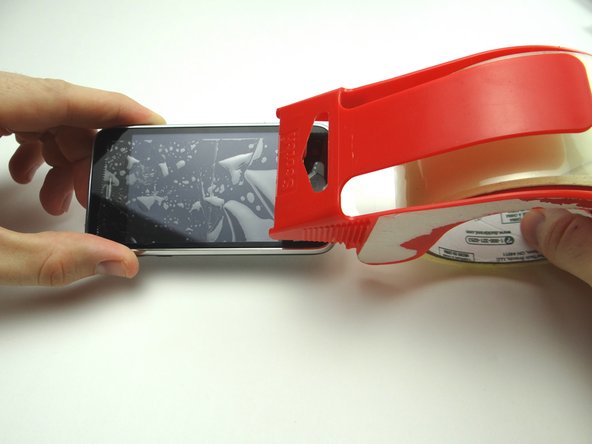
Picture 1: If you're replacing a cracked display, put a strip of packing tape across the screen.
-
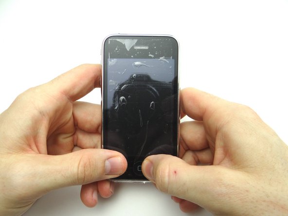
Picture 2: Seal the tape over the home button to ensure it comes up with the screen.
-
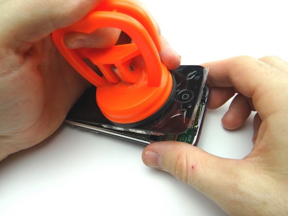
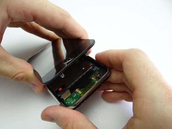
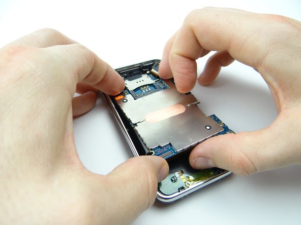
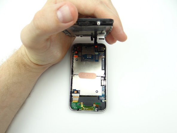
Picture 3: Pry up just enough to grab the screen with your fingers. Remove the suction cup.
-
If the screen still won't open, there's still another option for opening it in the next step.
-
-
-
If you're still unable to open the iPhone, use an iSesamo tool as a last resort:
-
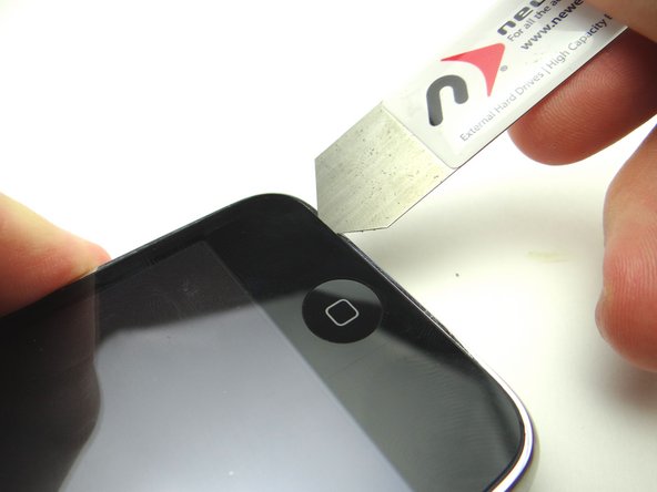
Picture 1: Wedge the iSesamo along the bottom edge of the iPhone near the corner.
-
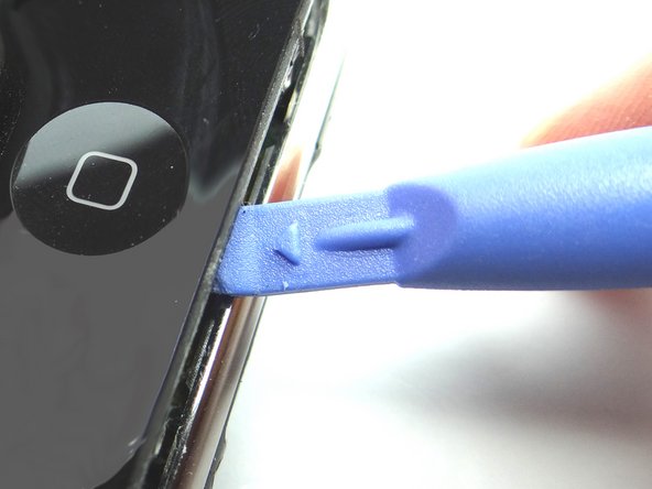
Picture 2: Pry up just enough to insert the blue pry tool.
-
Picture 3: Use the blue pry tool to continue prying up the screen.
-
-
-
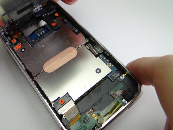
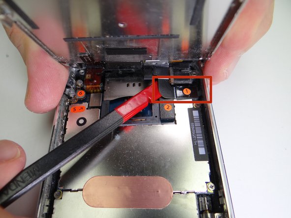
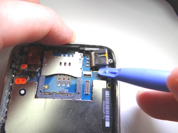
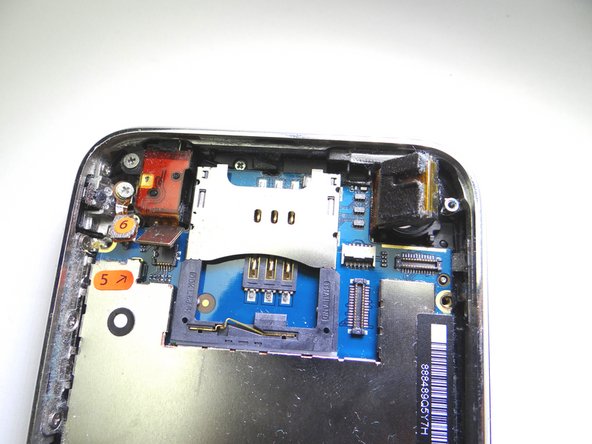
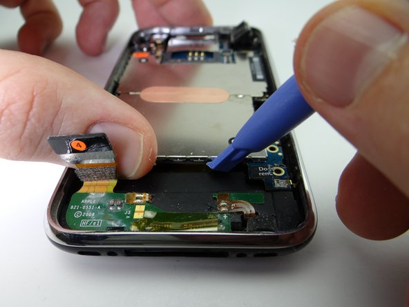
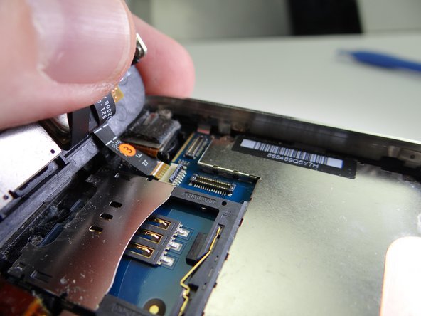
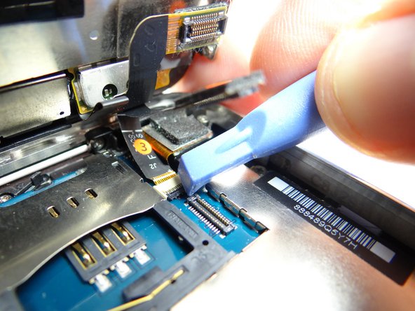
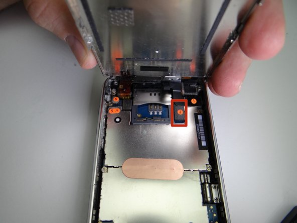
Picture 1: Use blue pry tool to lift cable 2 from its socket. You can now open the phone to a 90* angle.
-
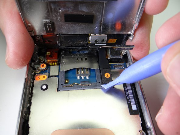
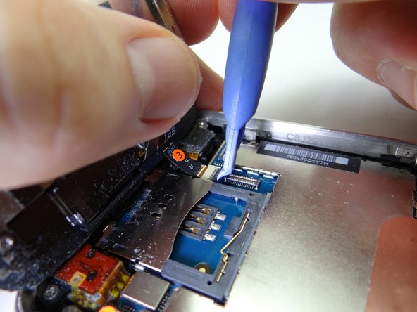
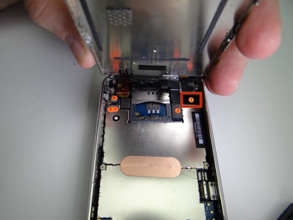
Pictures 2 & 3: Use the blue pry tool to flip the ZIF connector into the upright 'open' position to release the ribbon cable marked '3'.
-
Use your thumb to gently guide the ribbon cable out of the ZIF connector.
-
Cable '3' should come out with very little pressure. Double-check the ZIF connector latch if you feel tension.
-
-
-
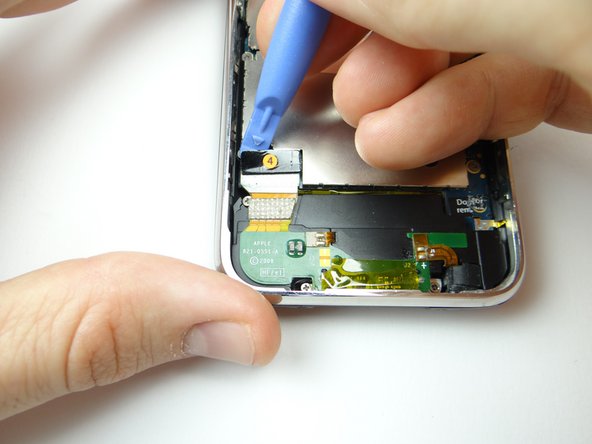
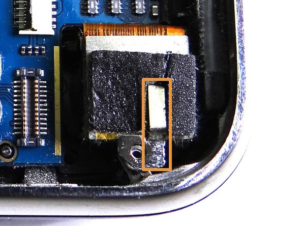
Picture 1: Use the blue pry tool to pull up foam piece covering cable 4 connector.
-
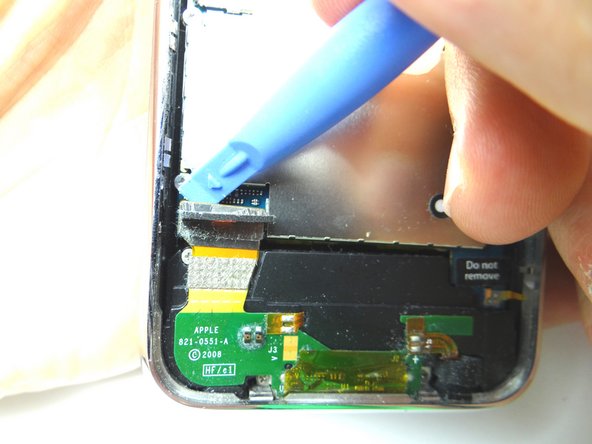
Picture 2: Pry up cable 4 connector with the blue pry tool.
-
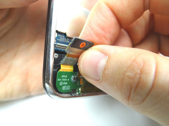
Picture 3: Squeeze foam back onto cable connector.
-
-
-
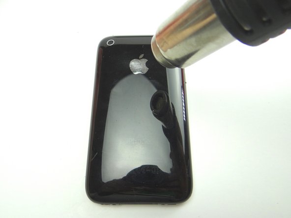
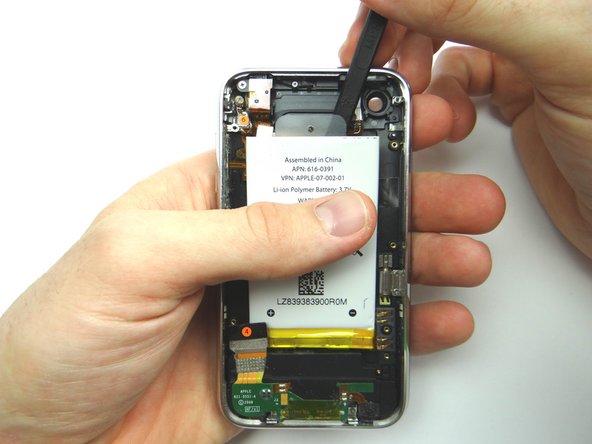
Picture 1: Adhesive around the perimeter of the battery holds it to the rear case. Apply low-level heat (100° Celsius) to the underside of the rear case for 30 seconds to loosen the adhesive.
-
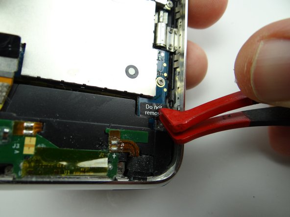
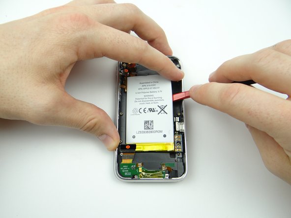
Picture 2: Use the spudger to push through the adhesive under the battery.
-
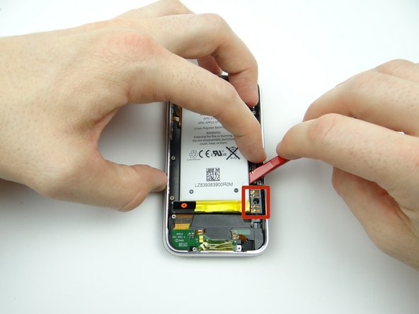
Picture 3: Work your way around the upper-right corner.
-
-
-
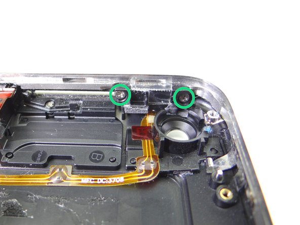
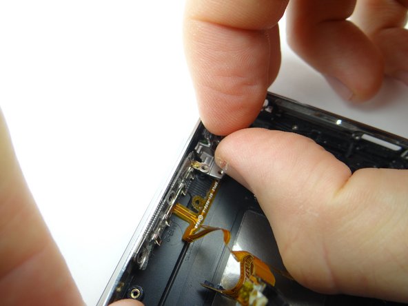
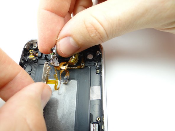
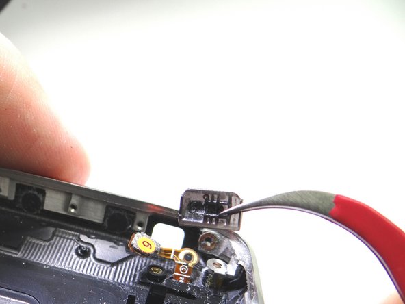
Picture 1: Remove two 1.9 mm Phillips screws. Place in COMPARTMENT C.
-
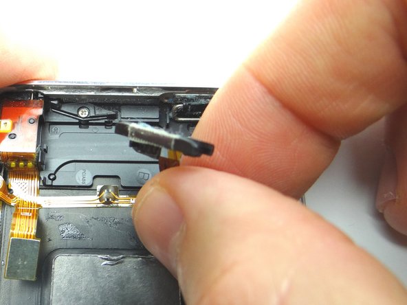
Picture 2: Peel power button cable away just enough to access the power button.
-
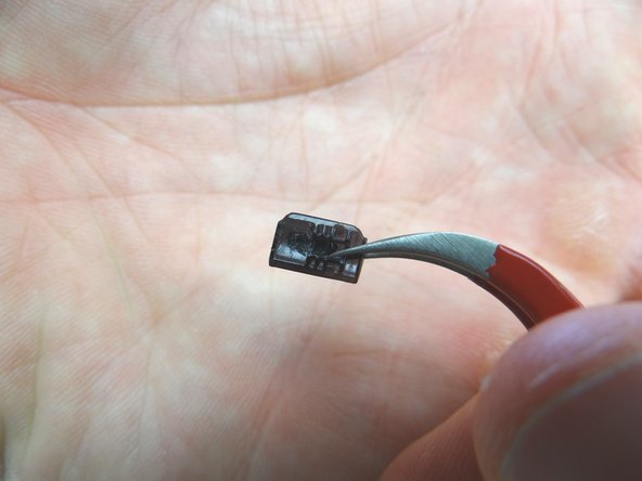
Picture 3: Remove power button with curved tip tweezers. Place with screws in COMPARTMENT C.
-
-
-
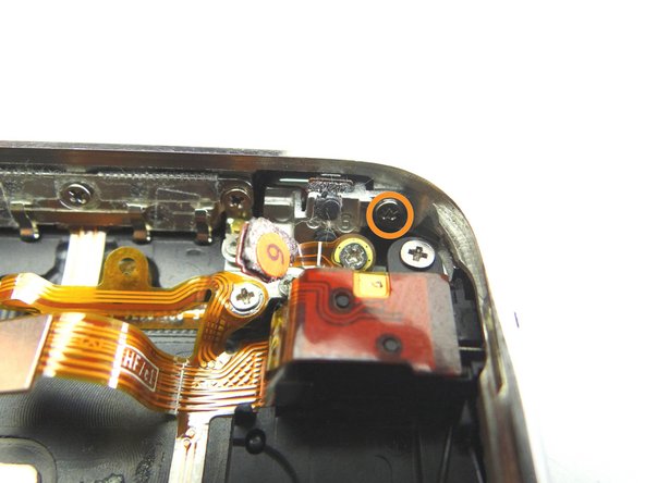
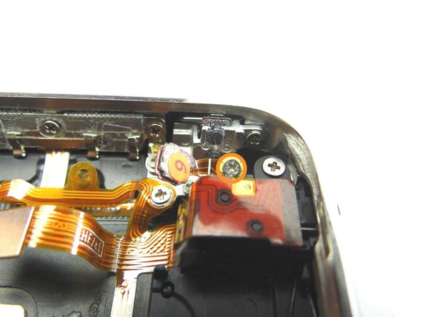
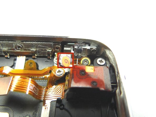
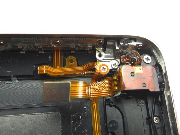
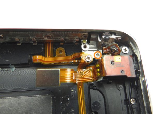
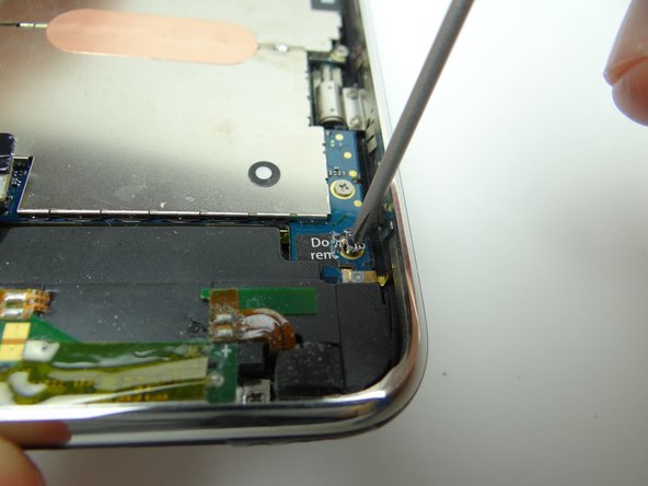
Picture 1: Remove 1.9 mm Phillips screw. Place in SLOT 9.
-
Picture 2: Remove 3.8 mm Phillips screw. Place in SLOT 10.
-
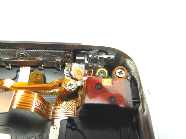
Picture 3: Remove 1.8 mm Phillips screw. Place in SLOT 11.
-
-
-
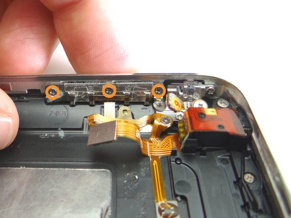
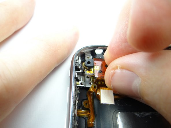
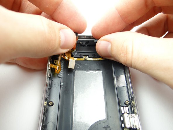
Picture 1: Peel up volume / mute / headset / power cable assembly. Place in COMPARTMENT E.
-
-
-
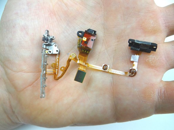
Picture 1: Retrieve the volume / mute / headset / power cable assembly from COMPARTMENT E.
-
Picture 2: Retrieve the replacement cable.
-
-
-
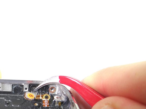
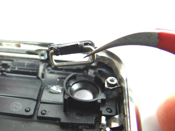
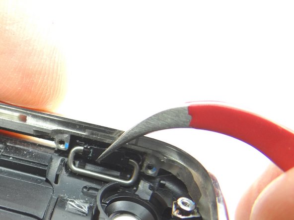
From COMPARTMENT D, use tweezers to replace the mute switch. The pictures show the correct orientation.
-
-
-
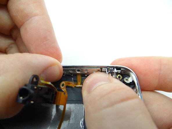
From COMPARTMENT C, use curved-tip tweezers to place the power button.
-
Push the power button into place. The pictures show the correct orientation.
-
-
-
Seat the power button cable and bracket.
-
FROM COMPARTMENT C, replace two 1.9 mm Phillips screws.
-
The power button should have some play without feeling loose or tight: After tightening the screws, press the power button a few times. Loosen or tighten the screws a quarter turn as needed.
-
-
-
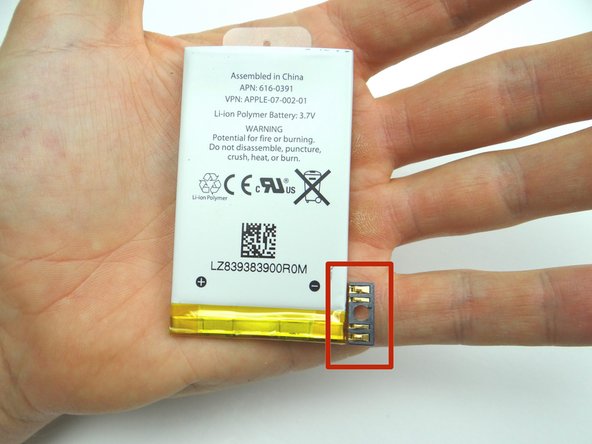
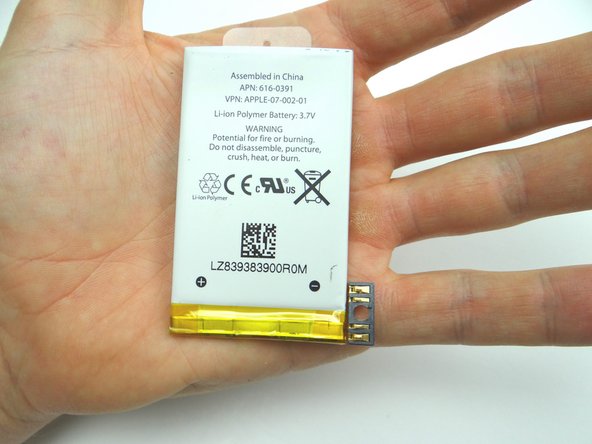
Place the battery in the rear case: seat the contact pad first, then continue seating the battery.
-
-
-
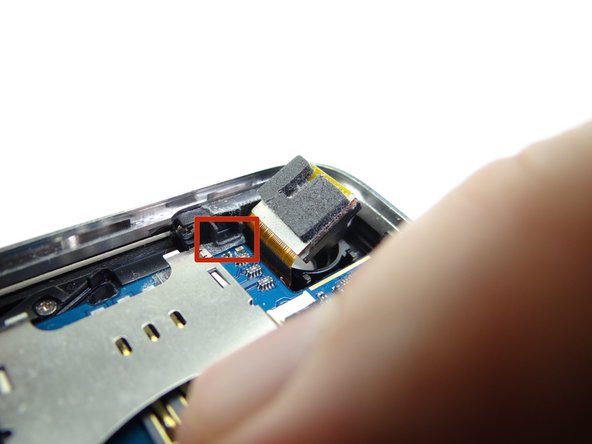
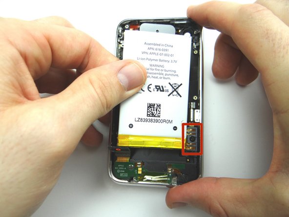
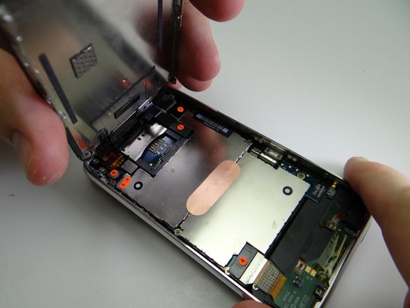
Pictures 1 & 2: From ZONE III, seat top of logic board first. Make sure the logic board is situated below the ledge shown in the red square.
-
Picture 3: Hold the charging port cable out of the way while seating the bottom of the logic board.
-
-
-
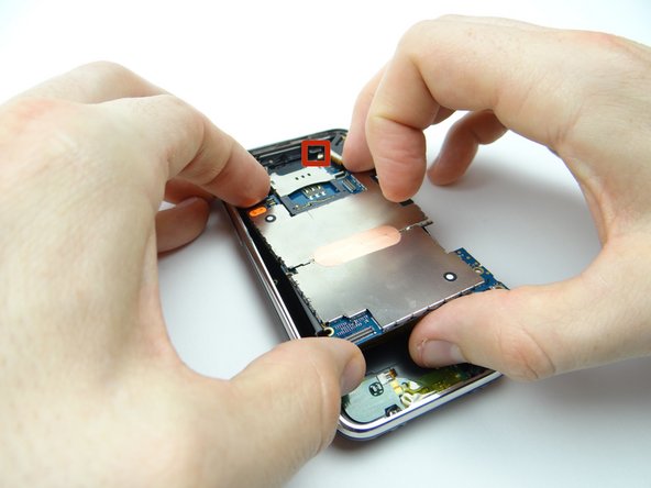
Picture 1: Reattach front panel to rear case:
-
Picture 2: Guide cable '3' into the ZIF connector.
-
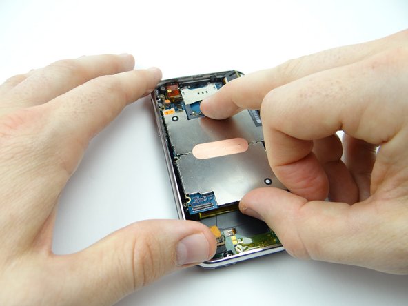
Picture 3: Use the blue pry tool to sweep down black swing bar to close ZIF connector.
-